
RCWI-6G - Wine cellar Royal Catering - Free user manual and instructions
Find the device manual for free RCWI-6G Royal Catering in PDF.

| Product Type | Wine cooler |
| Brand | Royal Catering |
| Model | RCWI-6G |
| Dimensions (L x D x H) | 643 x 595 x 820 mm |
| Weight | 47.5 kg |
| Chamber volume | 138 L |
| Bottle capacity (0.75 L) | 52 bottles |
| Power supply | 230 V ~ / 50 Hz |
| Rated current | 0.5 A |
| Protection class | I |
| Refrigerant / quantity | R600a / 50 g |
| Climate class | N, ST |
| Energy efficiency class | G |
| Energy consumption | 0.405 kWh/24h (148 kWh/year) |
| Temperature range | 5 °C to 22 °C |
| Defrosting | Automatic |
| Insulation | Cyclopentane |
| Interior lighting | LED |
| Humidity control | Integrated water reservoir |
| Reversible door | Yes (left or right mounting) |
| Display | LCD |
| Noise level | Low (quiet design) |
| Maintenance | Clean with soft cloth and mild products; automatic defrosting |
Frequently Asked Questions - RCWI-6G Royal Catering
User questions about RCWI-6G Royal Catering
0 question about this device. Answer the ones you know or ask your own.
Ask a new question about this device
Download the instructions for your Wine cellar in PDF format for free! Find your manual RCWI-6G - Royal Catering and take your electronic device back in hand. On this page are published all the documents necessary for the use of your device. RCWI-6G by Royal Catering.
USER MANUAL RCWI-6G Royal Catering
natural_image
Abstract white line drawing of a mythical creature on a blue background (no text or symbols)| DE | Produktname: | WEINKÜHLER |
| EN | Product name: | WINE COOLER |
| PL | Nazwa produktu: | LODÓWKA DO WINA |
| CZ | Název výrobku | CHLADNIČKA NA VÍNO |
| FR | Nom du produit: | CAVE À VIN |
| IT | Nome del prodotto: | VETRINA FRIGO PER VINO |
| ES | Nombre del producto: | NEVERA PARA VINO |
| HU | Termék neve | BORHÚTŐ |
| DA | Produktnavn | VINK∅LER |
| DE | Modell: | RCWI-4GRCWI-6GRCWI-7G |
| EN | Product model: | |
| PL | Model produktu: | |
| CZ | Model výrobku | |
| FR | Modèle: | |
| IT | Modello: | |
| ES | Modelo: | |
| HU | Modell | |
| DA | Model | |
| DE | Hersteller | expondo Polska sp. z o.o. sp. k. |
| EN | Manufacturer | |
| PL | Producent | |
| CZ | Výrobce | |
| FR | Fabricant | |
| IT | Produttore | |
| ES | Fabricante | |
| HU | Termelő | |
| DA | Producent | |
| DE | Anschrift des Herstellers | ul. Nowy Kisielin – Innowacyjna 7, 66-002 Zielona Góra | Poland, EU |
| EN | Manufacturer Address | |
| PL | Adres producenta | |
| CZ | Adresa výrobce | |
| FR | Adresse du fabricant | |
| IT | Indirizzo del produttore | |
| ES | Dirección del fabricante | |
| HU | A gyártó címe | |
| DA | Producentens adresse |


1 - Gehäuse
natural_image
Technical line drawing of a mechanical assembly with no visible text or symbols
natural_image
Technical diagram of a mechanical bracket with dashed lines indicating motion or force directions (no text or symbols)
natural_image
Line drawing of a door frame with a triangular handle and directional arrows indicating movement (no text or symbols)
natural_image
Technical line drawing of a mechanical assembly with no visible text or symbols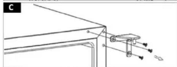
natural_image
Technical line drawing of a mechanical assembly with no visible text or symbols
natural_image
Technical line drawing of a door frame with a circular component and a small inset detail (no text or symbols)
natural_image
Pure technical line drawing of a corner bracket with mounting holes and a directional arrow (no text or symbols)

natural_image
Pure technical line drawing of a structural frame with mounting holes and diagonal braces (no text or symbols)
natural_image
Technical line drawing of a window frame with ventilation grilles and a 20-degree angle标注 (no text or symbols beyond measurement)
natural_image
Pure technical line drawing of a mechanical assembly without any text, numbers, or symbols
natural_image
Mechanical assembly diagram showing a spring-loaded component with directional arrow (no text or symbols)
natural_image
Mechanical assembly diagram showing a spring-loaded component inserted into a housing (no text or symbols)natural_image
Technical line drawing of two empty wine bottles in a rack, showing internal compartments (no text or labels)CAUTION! This User Manual has been translated for your convenience using machine translation. Reasonable efforts have been made to provide an accurate translation; however, no automated translation is perfect nor is it intended to replace human translators. The official User Manual is the English version. Any discrepancies or differences created in the translation are not binding and have no legal effect for compliance or enforcement purposes. If any questions arise related to the accuracy of the information contained in the User Manual, please refer to the English version of those contents which is the official version.
Technical Data
| Parameter description | Parameter value | ||
| Product name | WINE COOLER | ||
| Model | RCWI-4G | RCWI-6G | RCWI-7G |
| Supply voltage [V~] / Frequency [Hz] | 230~/50 | ||
| Rated current [A] | 0.7 | 0.5 | 0.4 |
| Safety class | I | ||
| Refrigerant/amount of refrigerant [g] | R600a/26 | R600a/50 | R600a/20 |
| Chamber volume [L] | 137 | 138 | 56 |
| Chamber capacity expressed in the number of wine bottles [pcs]*. | 46 52 20 | ||
| Climate class | N, SN, ST | N, ST | |
| Energy efficiency class | G | ||
| Energy use [kWh/24h] | 0.400 | 0.405 | 0.375 |
| Annual energy use [kWh/year] | 146 148 137 | ||
| Isolating substance | Cyclopentane | ||
| Cooling temperature control range[°C] | 5-22 | ||
| Defrosting function | auto | ||
| Dimensions (Width x Depth x Height) [mm] | 645 x 630 x 930 | 643 x 595 x 820 | 643 x 295 x 821 |
| Weight [kg] | 45 | 47.5 | 28.5 |
* The design of the shelves used inside the refrigeration chamber allows for storage of 0.75 L type bottles. The maximum filling level of the refrigeration compartment is given on their basis.
1. General Description
The instruction manual is intended to assist in safe and reliable use. The product is designed and manufactured strictly according to technical specifications using the latest technology and components and maintaining the highest quality standards.
CAREFULLY READ AND UNDERSTAND THIS MANUAL BEFORE PROCEEDING.
To ensure long and reliable operation of the unit, make sure to operate and maintain it properly in accordance with the guidelines in this instruction manual. The technical data and specifications contained in this instruction manual are up to date. The manufacturer reserves the right to make changes in order to improve the quality. Taking the technical progress and the possibility of reducing noise into account, the unit is designed and built in such a way so that risks resulting from noise emissions are reduced to the lowest possible level.
Explanation of symbols
The product complies with applicable safety standards.
Please read the instructions before use.
Recyclable product.
CAUTION! or WARNING! or REMINDER! General warning sign.
CAUTION! Warning of electric shock!
CAUTION! Danger of fire - flammable material!
For indoor use only.
CAUTION! The illustrations in this instruction manual are for the only and may differ from the actual product in some details.
2. Safety of use

CAUTION! Read all safety warnings and all instructions. Failure to follow the warnings and instructions may result in electric shock, fire and/or severe personal injury or death.
The term "unit" or "product" in the warnings and in the description of the instructions refers to the WINE COOLER.
2.1. Electrical safety
a) The plug of this unit must fit into the outlet. Do not modify the plug in any way. Original plugs and matching outlets reduce the risk of electric shock.
b) Avoid touching grounded parts, such as pipes, heaters, ovens, and refrigerators. There is an increased risk of electric shock if your body is grounded and touches the unit exposed to direct rain, wet pavement, and operation in a humid environment. If water enters the unit, there is an increased risk of damage to the unit and electric shock.
c) Do not touch the unit with wet or damp hands.
d) Do not use the cord in an unintended manner. Never use it to carry the unit or to pull the plug out of the socket. Keep the cord away from heat sources, oil, sharp edges or moving parts. Damaged or tangled cords increase the risk of electric shock.
e) If you cannot avoid using the unit in a wet environment, use a residual current unit (RCD). Using an RCD reduces the risk of electric shock.
f) Do not use the unit if the power cord is damaged or shows signs of wear. A damaged power cord should be replaced by a qualified electrician or the manufacturer's service department.
g) To avoid electric shock, do not immerse the cable, plug, or unit itself in water or other liquid. Do not use the unit on wet surfaces.
h) CAUTION - THREAT TO LIFE! When cleaning or using the unit, never immerse it in water or other liquids.
2.2. Safety in the workplace
a) Keep the work area tidy and well lit. Disorder or poor lighting can lead to accidents. Be foresighted, watch what you are doing and use common sense when using the unit.
b) If you find any damage or irregularities in the operation of the unit, immediately turn it off and report it to an authorized person.
c) If you have any doubts as to whether the product is working properly or if it is damaged, contact the manufacturer's service department.
d) Only the manufacturer's service department can repair the unit. Do not carry out repairs yourself!
e) In case of open flames or fire, use only dry powder or snow (CO2) fire extinguishers to extinguish the live equipment.
f) Check the condition of the safety stickers regularly. Replace them if they are illegible.
g) Keep these instructions for use for future reference. If the unit is to be passed on to a third party, the operating instructions must also be handed over together with the unit.
h) Keep the packaging and small assembly parts out of the reach of children.
i) Keep the unit away from children and animals.

Please note! Keep children and other bystanders safe while operating the unit.
2.3. Personal safety
a) The unit is not intended to be used by persons (including children) with reduced mental, sensory or intellectual functions or persons who lack experience and/or knowledge unless they are supervised or have been instructed by a person responsible for their safety on how to operate the unit.
b) To prevent accidental start-up, make sure the switch is in the off position before connecting to a power source.
c) The unit is not a toy. Children should be watched to ensure that they do not play with the unit.
d) Do not place your hands or any objects inside the running unit!
2.4. Safe use of the unit
a) Do not overload the unit. Use tools that are suitable for the application. A correctly selected unit will do a better and safer job for which it was designed.
b) Do not use the unit if the ON/OFF switch does not function properly (does not turn on and off). Units that cannot be controlled by the switch are unsafe, cannot operate, and must be repaired.
c) Disconnect the unit from the power supply before adjusting, cleaning, or servicing. This precaution reduces the risk of accidental start-up.
d) Keep unused equipment out of the reach of children and out of the reach of anyone unfamiliar with the unit or this instruction manual. These units is dangerous in the hands of inexperienced users.
e) Keep the unit in good working condition. Check before each use for general damage or damage to moving parts (cracks in parts and components or any other condition that may affect the safe operation of the unit). If damaged, have the unit repaired before use.
f) Repairs and maintenance should be carried out by qualified personnel using only original spare parts. This will ensure the safety of use.
g) To ensure the designed operational integrity of the unit, do not remove factory-installed covers or loosen screws.
h) When transporting or moving the unit from storage to the place of use, observe the health and safety rules for manual handling applicable in the country where the unit is used.
i) Do not move, shift, or rotate the unit while in operation.
j) Clean the unit regularly to prevent permanent dirt build-up.
k) The unit is not a toy. Cleaning and maintenance must not be performed by children without adult supervision.
I) Do not tamper with the unit to alter its performance or design.
m) Keep the unit away from sources of fire and heat.
n) Do not block the ventilation openings of the unit!
o) Ensure that the power supply to the unit corresponds to that specified on the identification plate!
p) The unit must be connected directly to a wall plug socket.
q) After delivery of the unit, wait 8 hours for the refrigerant used inside the unit to stabilize before connecting to the mains.
r) Do not install the unit close to equipment generating high temperatures/heat (heaters, boilers) and do not install the unit in direct sunlight!
s) Do not damage the refrigerant circuit.
t) Do not allow the rear coils of the unit to come into contact with the wall surface.
u) CAUTION! The unit in its construction contains flammable substances! If the unit is damaged, avoid contact with open flames, as well as the room in which the instrumentation is located should be thoroughly ventilated!
v) Do not place the unit in the vicinity of flammable materials such as paper or other materials.
w) Do not place heavy objects on the unit.
x) There is a risk of children getting stuck inside the unit. Before storing the end-of-life unit, cut off the wiring at the back of the unit and disable the door lock so that children cannot get stuck inside the unit.
y) The unit is not designed to freeze food products.
z) The factory set shelves provide the most efficient use of energy by refrigeration equipment.
aa) Do not use electrical appliances inside the refrigerator other than those provided by the manufacturer.
bb) Do not operate the unit in unheated areas.
cc) Do not open the door to the unit too often or leave it open for long periods of time. This results in increased electricity consumption, which can lead to possible damage to the unit.
dd) If the refrigeration unit remains unfilled for a long time, turn it off. Defrost, clean, dry and leave the door open to prevent mold growth inside the unit.
ee) The use of external electrical appliances to speed up the defrosting process is prohibited.
ff) Do not store explosive substances, such as cans containing compressed flammable gas, inside the unit.
gg) Installation of the unit should be carried out by qualified personnel.

CAUTION! Although the product has been designed to be safe, with adequate safeguards, and despite the additional safety features provided to the user, there is still a slight risk of accident or injury when handling the unit. You are advised to use caution and common sense when using this product.
3. Rules of use
The unit is designed for storing beverages in external vessels, using the appropriate temperature. The area of use includes only households and their derivatives.
The user is responsible for any damage resulting from misuse.
3.1. Description of the unit
flowchart
graph TD
    b --> c
    c --> g
    g --> h
    h --> d
    d --> e
    e --> b
    style g fill:#f9f,stroke:#333
    style h fill:#f9f,stroke:#333
    style d fill:#f9f,stroke:#333
    style e fill:#f9f,stroke:#333
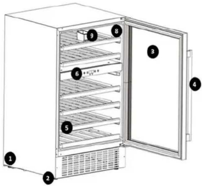
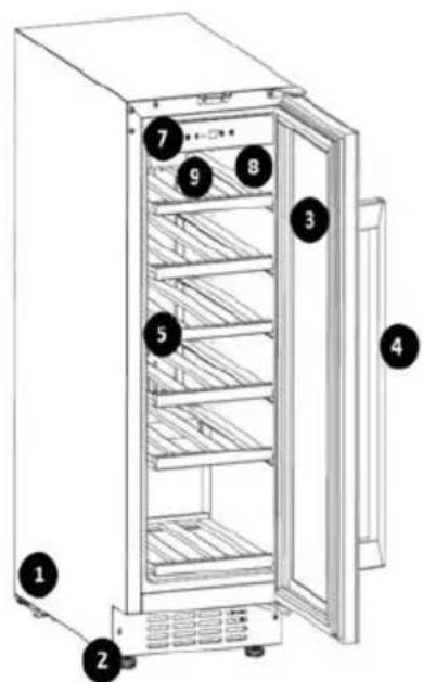
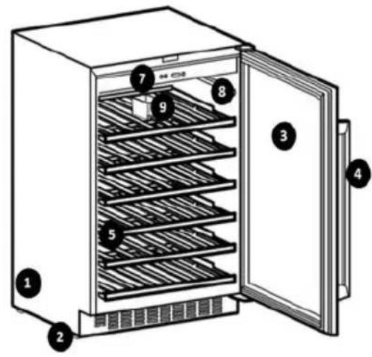
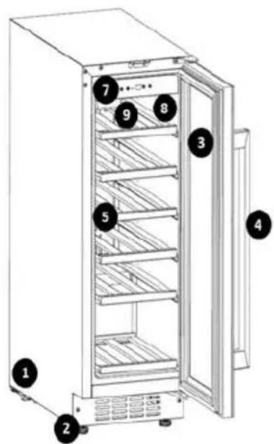
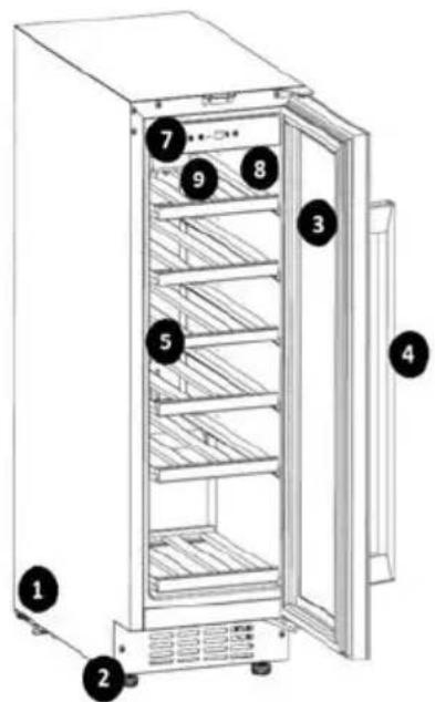
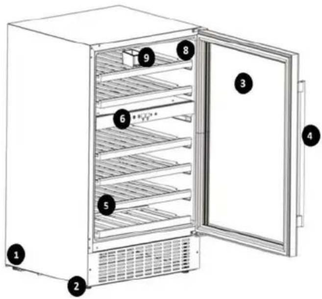
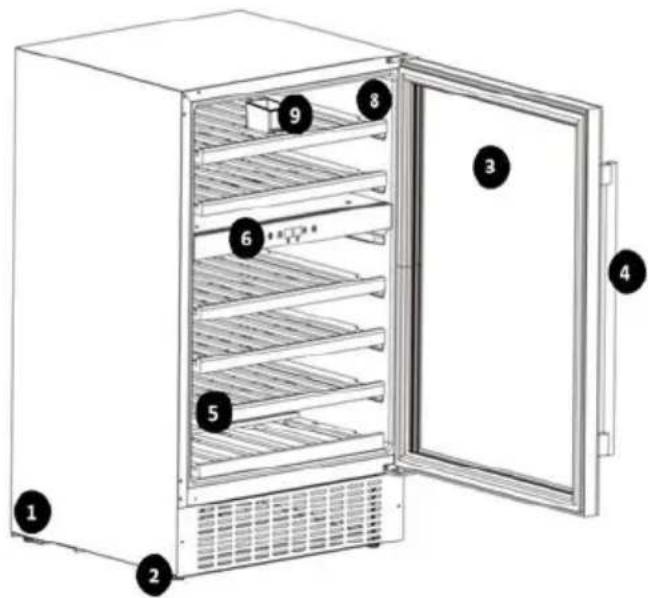
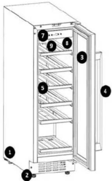
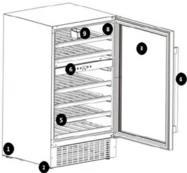
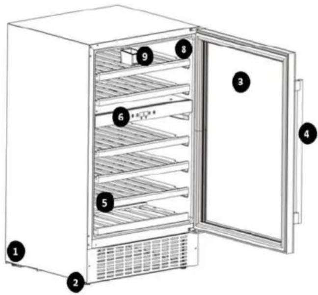
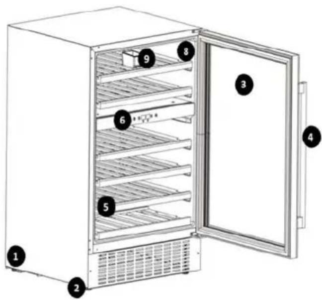
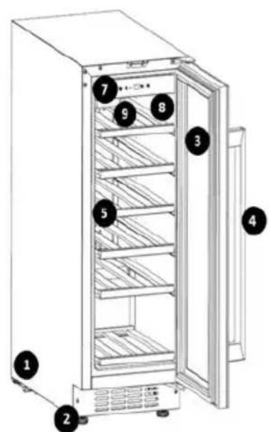
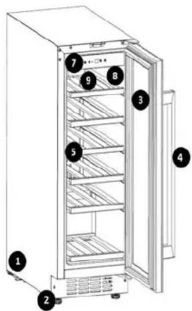
1 – Casing
2 - Anti-slip base
3 - Door
4 - Handle
5 - Shelf
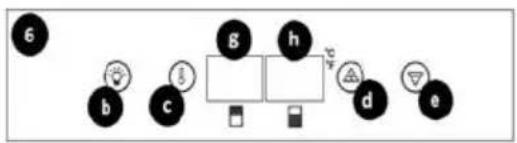
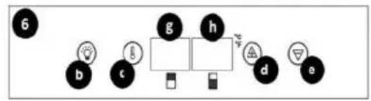
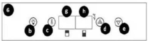
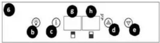
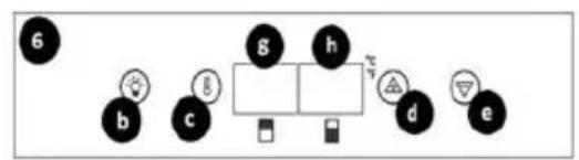
6 - Control panel model RCWI-4G
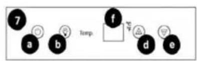
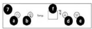
7 - Control panel model RCWI-6G / RCWI-7G
8 - Cooling chamber
9 - Hopper
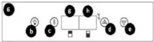
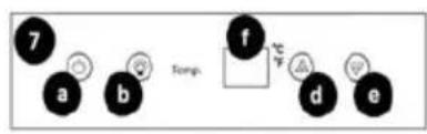
a - Power switch
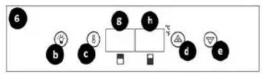
b - LED chamber lighting button
c - Temperature regulation button
d - Button for regulation, increasing value
e - Button for adjusting, decreasing value
f - LCD display
g - LCD display of the upper zone
h - LCD display of the lower zone
3.2. Preparation for operation
POSITIONING OF THE UNIT
The ambient temperature for each model must not exceed the following range: 10-32°C - model RCWI-4G; 16-38°C - model RCWI-6G; 10-38°C - model RCWI-7G. Place the unit in a way that ensures good air circulation. Maintain a minimum distance of 30 cm between the rear wall of the unit. Keep the unit away from any hot surfaces. Always operate the unit on a level, stable, clean, fireproof and dry surface and out of the reach of children and persons of impaired mental, sensory and intellectual functions. Place the unit in such a way that the mains plug can be reached at any time. Ensure that the power supply to the unit corresponds to that specified on the identification plate!
BEFORE INITIAL USE
Before the first use, disassemble all components and wash them as well as wash the interior and exterior of the unit.
CAUTION! Before the unit is connected to the mains, it may generate a characteristic odor, which will gradually escape as the unit reaches the programmed temperature.
ASSEMBLY OF THE UNIT
The unit has a right-hand door configuration at the factory, but it is possible to install the door as a left-hand door according to the user's preference. The unit is designed for free-standing or built-in operation.
a) CAUTION! Before proceeding to the removal / installation of the door, properly secure the unit so that no damage occurs. Remove all moving parts from inside the unit. Before tilting the unit, protect the refrigerant system circuit by laying a soft material at the surface contact point!
b) To change the installation side of the door, laying the unit on the rear panel is recommended.
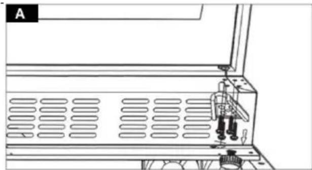
c) Holding the unit door, remove the lower hinge by unscrewing its fastenings (Figure A).
d) Carefully slide the door out of the upper hinge pin (Fig. B). Place the removed door in a safe place, with the outer panel up.
e) CAUTION! Pay attention to the set of removed fixings. Check that the fixings are not left where the door meets the housing, seal, etc.
f) Remove the upper hinge of the unit door by unscrewing its fastenings (Figure C).
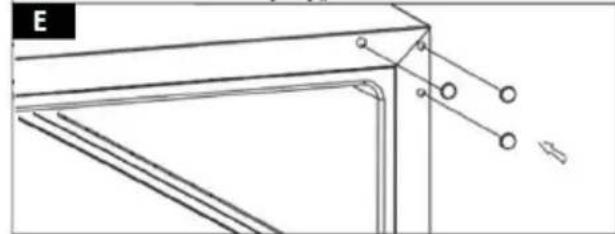
g) In the upper left corner of the unit in the place of fixing the hinge, lever up and remove the covers of the mounting holes (Fig. D).
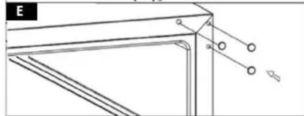
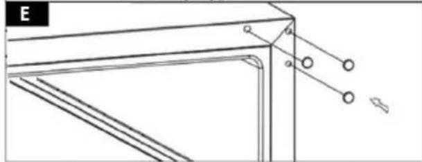
h) Cover the mounting holes left by the hinge mountings of the right side with the previously removed covers (Fig. E).
i) Install the left side hinge, screwing its mountings into the designated mounting holes (Fig. F).
j) Turn the door of the unit by 180^ and slide it into the mounting pin of the left hinge.
k) Install the bottom hinge of the left side. Slide the hinge pin into the dedicated mounting hole of the door and fix with the fasteners (Fig. G).
I) Install the unit door bracket (fig. H).
m) To do this, remove the gasket on the inside of the door. The structure of the unit, under the sealing element, contains dedicated mounting holes.
n) CAUTION! Regardless of the side of the installation of the bracket (left / right), the factory designed mounting holes for each side.
o) Prepare the mounts. Slide a lock washer onto the mounting screw, followed by a flat washer.
p) Apply the unit bracket from the outside of the door. Align the axes of the mounting holes of the bracket and the door.
q) Pass the previously prepared mounting structure through the top and bottom mounting holes. Press the mounts together.
r) Reinstall the gasket at the dedicated location.
s) In order to build the unit, it is necessary to install a suitable bracket, attaching the unit with the upper housing. The connecting bracket is supplied with the unit. The mounting of the bracket should be selected individually, according to the regulations of your country.
t) Install the connecting bracket at the top of the unit, in place of the dedicated mounting holes. Embed the unit in the target location and attach it to the top of the housing (see Figure H).
u) Adjust the level/height of the unit using the front bases (their rotation clockwise or counterclockwise).
v) CAUTION! Due to the tilting of the unit during door installation, wait 8 hours for the refrigerant used inside the unit to stabilize before connecting the fixture to the mains!
natural_image
Technical line drawing of a mechanical assembly with no visible text or symbols
natural_image
Technical diagram of a metal bracket with dashed arrows indicating direction and an arrow symbol (no text or labels)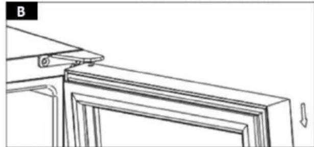
natural_image
Technical line drawing of a door frame with mounting bracket and directional arrows (no text or symbols)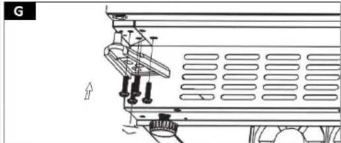
natural_image
Technical line drawing of a mechanical assembly with mounting brackets and a ventilation grille (no text or symbols)
natural_image
Technical line drawing of a mechanical assembly with mounting bracket and support structure (no text or symbols)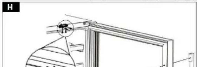
natural_image
Technical line drawing of a door frame with a circular component and a magnified inset showing a detail (no text or symbols)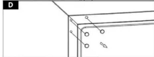
natural_image
Pure technical line drawing of a corner bracket with mounting holes and mounting points (no text or symbols)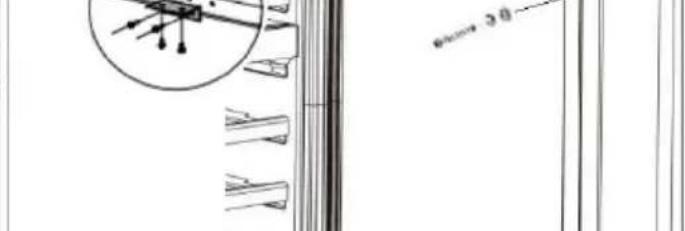
natural_image
Pure technical line drawing of a structural frame with no text, numbers, or symbols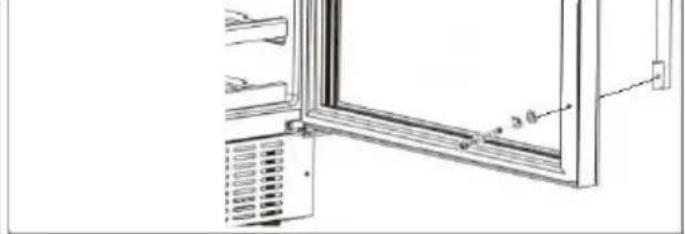
natural_image
Technical line drawing of a window frame with ventilation grilles and a 3.0 mm dimension label (no text or symbols beyond measurement)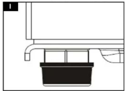
natural_image
Pure technical line drawing of a mechanical assembly without any text, numbers, or symbols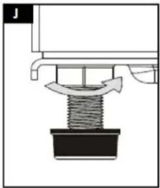
natural_image
Mechanical assembly diagram showing a spring-loaded component with a curved arrow indicating motion (no text or symbols)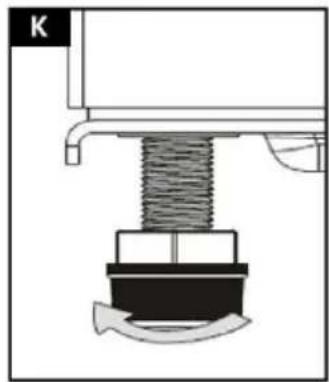
natural_image
Mechanical assembly diagram showing a spring-loaded component with a curved arrow indicating motion (no text or symbols)3.3. Working with the unit
Before working with the unit, connect the necessary power cords to the unit. Familiarize yourself with the parameters/functions of the unit. After starting the system, set the desired parameters as described below.
CAUTION! When the unit is first connected to the mains and the cooling temperature is programmed (or after a long break from use), there may be a temperature difference between the setpoint (displayed on the control panel) and the temperature inside the refrigeration compartment. This temperature will stabilize with continuous operation of the unit. Do not open the unit door during the temperature stabilization process. If the unit shuts down during the cooling process, wait about 5 minutes before restarting the system (otherwise the unit will not turn on).
3.3.1. STARTING THE UNIT / TEMPERATURE SETTINGS
CAUTION! Any configuration of the cooling chamber cooling temperature, generates increased operation of the refrigerant circuit, which may lead to the unit housing reaching high temperatures. Once the system reaches the set threshold value, the unit panels will gradually cool down until the temperature value around the unit is reached.
MODEL RCWI-4G
a) The unit is started using the control panel, located in the central part of the cooling chamber.
b) To start the system, simultaneously select and hold the buttons (b, c) for about 5 seconds for LED lighting and temperature control.
c) The refrigeration compartment of the unit includes two cooling zones: upper and lower. Temperature configuration should be carried out separately, for each of them.
d) CAUTION! The upper and lower cooling zones have the same temperature control range. When defining the cooling value of the upper zone, the system will automatically assign the given value to the lower zone. The lower zone of the refrigeration compartment, can have the same chilling temperature value or higher, than the upper zone of the refrigeration compartment. The temperature difference between the cooling zones is recommended to be no more than 4 °C.
e) To set the chilling temperature value, select the temperature control button (c) from the control panel.
- A single selection of the adjustment button (c) will display the current chilling temperature value on the LCD screen.
- Double selection of the button will switch the system to the upper chill zone temperature configuration.
- Triple selection of the button will switch the system to the temperature configuration of the lower cooling zone
f) The currently presented temperature value on the LCD display will cycle on and off. Define the value of the desired cooling temperature using the adjustment buttons (d, e), increasing / decreasing the value. The temperature is adjusted in 1°C increments.
g) After defining the value of the cooling temperature, wait about 2 seconds until the entered value on the LCD screen stabilizes. The changes will be stored in the system memory.
h) It is possible to swap the unit's operating temperature units (F/°C). To adjust the unit's operating temperature units, from the control panel, select and hold the refrigeration compartment LED light button (c) for about 5 seconds.
i) The temperature unit (F/°C) of the unit's operation is displayed by the LED indicator, on the control panel.
| Function | Action | Controller | |
| Putting the unit into operation | 5 sec. | 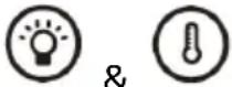 | x |
| Cooling temperature display | 1 x |  | |
| Upper zone temperature control | 2 x | ||
| Lower zone temperature control | 3 x | ||
| Convert temperature units (F/°C) | 5 sec. |  | x |
MODEL RCWI-6G / RCWI-7G
a) The unit is started using the control panel, located in the upper part of the refrigeration compartment.
b) To start the system, select and hold the unit's power switch (a) for about 5 seconds.
c) To set the value of the cooling temperature, select from the control panel the control buttons for increasing / decreasing (d, e) the temperature value. The temperature is adjusted in 1°C increments.
d) The currently presented temperature value on the LCD display will cycle on and off.
e) After defining the value of the cooling temperature, wait about 2 seconds until the entered value on the LCD screen stabilizes. The changes will be stored in the system memory.
f) It is possible to swap the unit's operating temperature units (F/°C). To adjust the unit's operating temperature units, from the control panel, select and hold the refrigeration compartment LED light button (c) for about 5 seconds.
g) The temperature unit (F/°C) of the unit's operation is displayed by the LED indicator, on the control panel.
| Function | Action | Controller | |
| Putting the unit into operation | 5 sec. |  | x |
| Cooling temperature control | x | 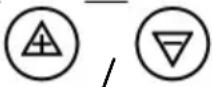 | |
| Convert temperature units (F/°C) | 5 sec. |  | x |
3.3.2. UNIT OPERATION (RCWI-4G / RCWI-6G / RCWI-7G MODEL)
a) Define the appropriate cooling temperature of the refrigeration compartment.
b) Turn on the illumination of the refrigeration compartment of the unit by selecting the LED illumination button (b) from the control panel. Selecting the button again will turn off the chamber illumination.
c) The unit is equipped with a system for maintaining the optimal humidity level inside the refrigeration compartment. The reservoir (9) that regulates the humidity level is located on dedicated rails, top shelf of the refrigeration chamber. Before filling the inside of the unit, fill the tank (9) with water in the order of 34 of the total volume and install in a dedicated location.
CAUTION! Check the filling level of the humidity control tank regularly. If necessary, refill the tank.
d) Fill the interior of the unit according to the instructions below. CAUTION! The cooling time of the cooling chamber charge depends on the number of bottles placed. Cooling of individual bottles is faster than when the chamber is fully occupied.
e) If there is a need to move the unit from its current location, remove all movable objects from inside the chamber. Secure the shelves and doors of the unit with tape for transport. Cover the outer panels of the unit with material to protect them from damage, such as scratches, etc.
BOTTLE STORAGE
f) The design of the shelves used inside the cooling chamber allows the storage of 0.75 L bottles. Based on them, the maximum filling level of the refrigeration chamber is given.
g) Before filling the interior of the unit with bottles of larger capacity, check whether the placed vessels will not affect the correct operation of the unit.
h) In order to maintain optimal access to the stored bottles, it is recommended to extend the shelves to about 1/3 of the depth of the chamber (especially for the lower shelves).
natural_image
Technical line drawing of two empty wine bottles in a rack, with no text or symbols present.i) CAUTION! Properly seated bottles inside the refrigeration chamber, after closing the unit door, should not touch the front or rear panel! Maintain adequate clearance between the load and the closed door and the rear panel of the unit!
3.4. Cleaning and maintenance
a) Pull out the mains plug before each cleaning and when the unit is not in use.
b) Only mild detergents designed for cleaning food contact surfaces may be used to clean the unit.
c) After each cleaning, all the parts should be dried well before the unit is used again.
d) Store the unit in a dry and cool place protected from moisture and direct sunlight.
e) Do not spray the unit with a stream of water or immerse it in water.
f) Make sure that no water enters through the ventilation openings in the casing.
g) Clean the ventilation openings with a brush and compressed air.
h) Perform regular inspections of the unit checking technical fitness and any damages.
i) Use a soft cloth for cleaning.
j) Do not use sharp and/or metal objects (e.g. a wire brush or metal spatula) for cleaning, as these may damage the surface of the material from which the unit is made.
k) Do not clean the unit with acidic substances, medical products, diluent, fuel, oil or other chemicals as this may cause damage to the unit.
I) CAUTION! When pulling out the shelves for cleaning, make sure that the unit door opens to its full width! Otherwise the machine can be damaged.
m) The process of defrosting the refrigeration compartment is automatic and requires no additional action by the user. Be sure to periodically clean the evaporation tray and the defrost water drain hole, located at the rear of the unit, near the refrigerant system.
DISPOSAL OF USED UNITS.
At the end of its useful life, this product should not be disposed of with normal household waste but should be taken to a collection point for the recycling of electrical and electronic equipment. This is indicated by the symbol on the product, operating instructions or packaging. The materials used in this unit are recyclable according to their marking. You will be making an important contribution to protecting our environment by reusing, recycling or otherwise disposing of used units.
Your local administration will provide you with information about the appropriate disposal point for used units.
TROUBLESHOOTING
| Problem | Possible cause | Action |
| The unit does not turn on | No proper connection of the unit | Check the correct connection of the unit |
| Power switch off | Turn on the unit with the power switch | |
| No current in the power socket | Check voltage at power socket | |
| The fuse is damaged | Contact the manufacturer's service department. | |
| Cooling chamber temperature too high | Incorrectly defined cooling temperature | Perform chilling temperature configuration |
| Too high frequency of opening the unit door or leaving the door ajar for a long time | Check frequency and time of door opening | |
| Unit door not closed | Check that the door is tight / closed properly | |
| Failure in power supply of the unit | Reconnect the unit and wait a minimum of 4 hours for the cooling temperature to stabilize | |
| Cooling chamber temperature too low | Incorrectly defined cooling temperature | Perform chilling temperature configuration |
| The unit generates vibrations | Failure to level the unit properly | Re-level the unit |
| Incorrect distance between the rear panel of the unit and the wall / object behind it | Use the required safe distance of 30 cm | |
| x | Restart the unit. If the problem persists, contact the manufacturer's service department | |
| Occurrence of moisture inside the unit chamber | Too high frequency of opening the unit door or leaving the door ajar for a long time | Check frequency and time of door opening |
| Lack of proper door closing | Check that the door is tight / closed properly | |
| Occurrence of moisture on the outer panel of the unit door | Unit door ajar (contact with temperature difference between cooled air inside the chamber and room temperature air from outside the unit) | Check that the door is tight / closed properly |
1 - Obudowa
natural_image
Technical line drawing of a multi-stage bottle arrangement in a rack, showing internal compartments (no text or labels)


1 - Skřín
natural_image
Technical line drawing of a mechanical assembly with no visible text or symbols
natural_image
Technical diagram showing a bracket with dashed lines indicating light refraction or alignment, no text or symbols present
natural_image
Technical line drawing of a door frame with mounting bracket and side panel (no text or symbols)
natural_image
Technical line drawing of a vehicle chassis with structural components and mounting brackets (no text or symbols)
natural_image
Technical line drawing of a mechanical assembly with no visible text or symbols
natural_image
Technical line drawing of a door frame with a circular detail and a magnified inset showing a small object (no text or symbols)
natural_image
Pure technical line drawing of a corner bracket with mounting holes and a directional arrow (no text or symbols)
natural_image
Pure technical line drawing of a structural frame with mounting holes and diagonal braces (no text or symbols)
natural_image
Technical line drawing of a window frame with ventilation grilles and a 20-degree angle标注 (no text or symbols beyond measurement)
natural_image
Pure technical line drawing of a mechanical assembly without any text, numbers, or symbols
natural_image
Mechanical assembly diagram showing a spring-loaded component with a curved arrow indicating motion (no text or symbols)
natural_image
Mechanical assembly diagram showing a spring-loaded component inserted into a housing (no text or symbols)natural_image
Technical line drawing of two empty wine bottles in a rack, with no text or symbols present.

natural_image
Technical line drawing of a mechanical assembly with no visible text or symbols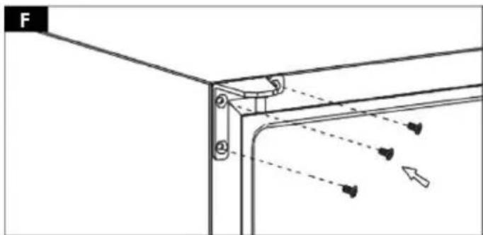
natural_image
Technical diagram of a mechanical bracket with dashed arrows indicating motion or force direction (no text or symbols)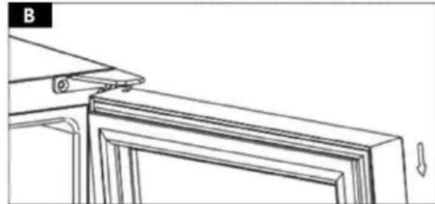
natural_image
Technical line drawing of a door frame with mounting bracket and side panel (no text or symbols)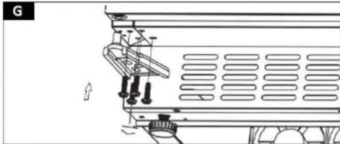
natural_image
Technical line drawing of a vehicle chassis with structural components and mounting brackets (no text or symbols)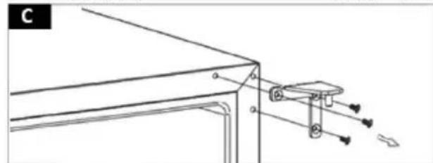
natural_image
Technical line drawing of a mechanical assembly with no visible text or symbols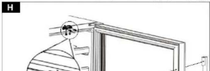
natural_image
Technical line drawing of a door frame with a circular detail and a magnified view of the lid (no text or symbols)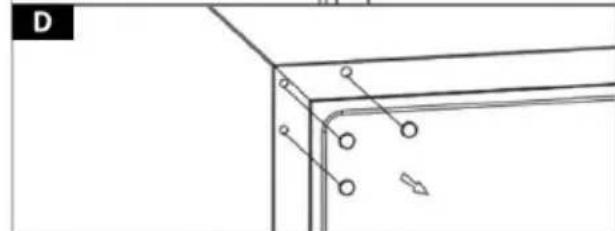
natural_image
Pure technical line drawing of a corner bracket with mounting holes and a directional arrow (no text or symbols)

natural_image
Pure technical line drawing of a structural frame with mounting holes and diagonal braces (no text or symbols)
natural_image
Technical line drawing of a window frame with ventilation grilles and a 20-degree angle标注 (no text or symbols beyond measurement)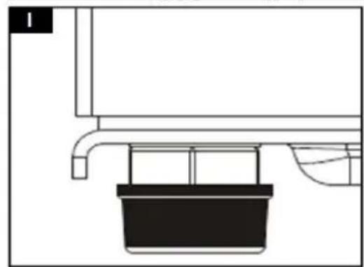
natural_image
Pure technical line drawing of a mechanical assembly without any text, numbers, or symbols
natural_image
Mechanical assembly diagram showing a spring-loaded component with directional arrow (no text or symbols)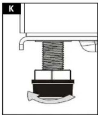
natural_image
Mechanical assembly diagram showing a spring-loaded component inserted into a housing (no text or symbols)natural_image
Line drawing of six identical empty bottles arranged in a row inside a rectangular frame (no text or symbols)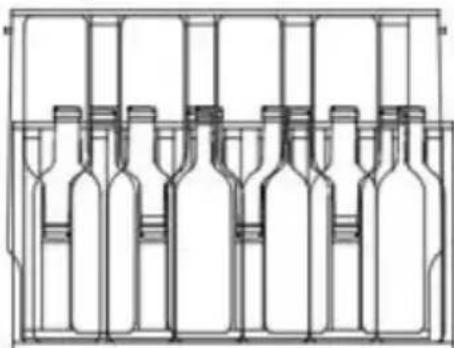
natural_image
Line drawing of a multi-volume wine bottle structure (no text or labels)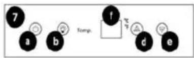
natural_image
Technical line drawing of a mechanical assembly with no visible text or symbols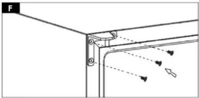
natural_image
Technical diagram of a mechanical bracket with dashed arrows indicating motion or force direction (no text or symbols)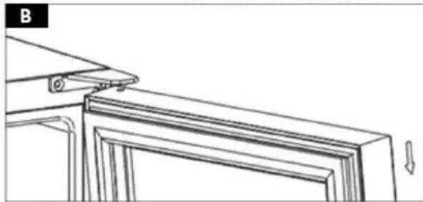
natural_image
Technical line drawing of a door frame with an attached bracket and directional arrows (no text or symbols)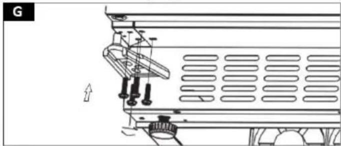
natural_image
Technical line drawing of a mechanical assembly with mounting brackets and a directional arrow (no text or symbols)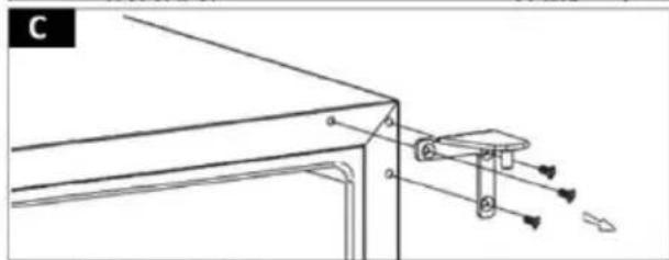
natural_image
Technical line drawing of a mechanical assembly with mounting bracket and support structure (no text or symbols)
natural_image
Technical line drawing of a door frame with a magnified inset showing a detail (no text or symbols)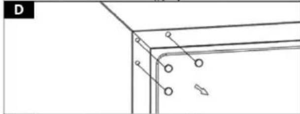
natural_image
Pure technical line drawing of a corner bracket with mounting holes and mounting points (no text or symbols)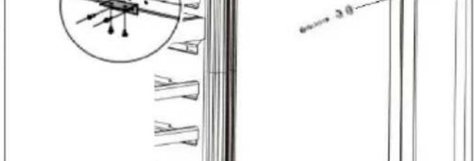
natural_image
Technical line drawing of a structural frame with mounting holes and connection points (no text or symbols)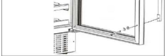
natural_image
Technical line drawing of a refrigerator with ventilation grilles and a door frame (no text or symbols)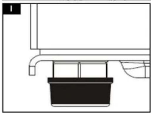
natural_image
Pure technical line drawing of a mechanical assembly without any text, numbers, or symbols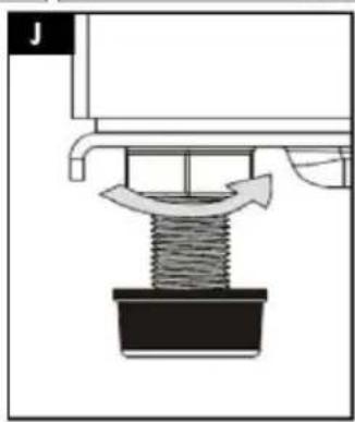
natural_image
Mechanical diagram showing a spring being inserted into a housing, with an arrow indicating motion (no text or symbols present)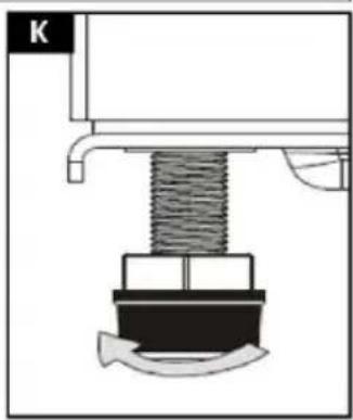
natural_image
Mechanical assembly diagram showing a spring-loaded component inserted into a housing (no text or symbols)natural_image
Technical line drawing of two empty wine bottles in a rack, with no text or symbols present.

natural_image
Technical line drawing of a mechanical assembly with no visible text or symbols
natural_image
Technical diagram showing a bracket with dashed lines indicating light refraction or alignment, no text or symbols present
natural_image
Line drawing of a door frame with a triangular handle and directional arrows indicating movement (no text or symbols)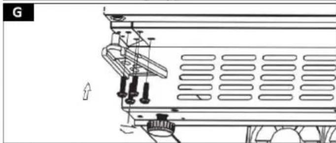
natural_image
Technical line drawing of a mechanical assembly with no visible text or symbols
natural_image
Technical line drawing of a mechanical assembly with no visible text or symbols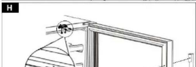
natural_image
Technical line drawing of a door frame with a circular component and a handle (no text or symbols)
natural_image
Pure technical line drawing of a corner bracket with mounting holes and a directional arrow (no text or symbols)

natural_image
Pure technical line drawing of a structural frame with mounting holes and diagonal braces (no text or symbols)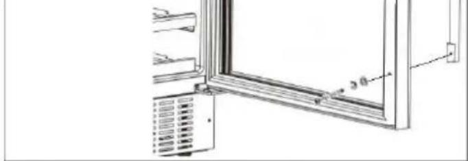
natural_image
Technical line drawing of a window frame with ventilation grilles and a 20-degree angle标注 (no text or symbols beyond measurement)
natural_image
Pure technical line drawing of a mechanical assembly without any text, numbers, or symbols
natural_image
Mechanical assembly diagram showing a spring-loaded component with a curved arrow indicating motion (no text or symbols)
natural_image
Mechanical assembly diagram showing a spring-loaded component inserted into a housing (no text or symbols)natural_image
Technical line drawing of a multi-stage bottle arrangement in a rack, showing internal compartments and no text or symbols.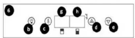
1 - Ház
natural_image
Technical line drawing of a mechanical assembly with no visible text or symbols
natural_image
Technical diagram of a mechanical bracket with dashed lines indicating motion or force direction (no text or symbols)
natural_image
Line drawing of a door frame with a triangular handle and directional arrows indicating movement (no text or symbols)
natural_image
Technical line drawing of a mechanical assembly with no visible text or symbols
natural_image
Technical line drawing of a mechanical assembly with no visible text or symbols
natural_image
Technical line drawing of a door frame with a circular component and a small inset detail (no text or symbols)
natural_image
Pure technical line drawing of a corner bracket with mounting holes and a diagonal arrow (no text or symbols)

natural_image
Pure technical line drawing of a structural frame with mounting holes and diagonal braces (no text or symbols)
natural_image
Technical line drawing of a window frame with ventilation grilles and a 20-degree angle标注 (no text or symbols beyond measurement)
natural_image
Pure technical line drawing of a mechanical assembly without any text, numbers, or symbols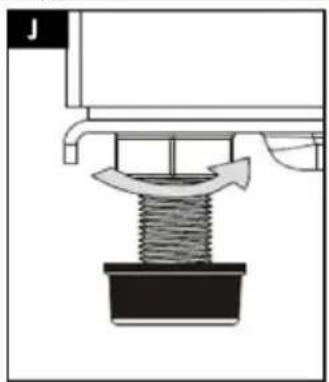
natural_image
Mechanical assembly diagram showing a spring-loaded component with directional arrow (no text or symbols)
natural_image
Mechanical assembly diagram showing a spring-loaded component inserted into a housing (no text or symbols)natural_image
Technical line drawing of a multi-stage bottle rack with multiple bottles in different storage compartments (no text or labels)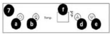

1 - Hus
2 – Skridsikker base
3 - Dør
4 - Håndtag
5 - Hylde
6 - Kontrolpanel model RCWI-4G
7 - Kontrolpanel model RCWI-6G / RCWI-7G
8 - Kølerum
9 - Beholder
APPARATETS PLACERING
natural_image
Technical line drawing of a mechanical assembly with no visible text or symbols
natural_image
Technical diagram of a mechanical bracket with dashed lines indicating motion or force directions (no text or symbols)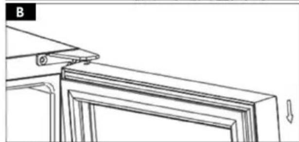
natural_image
Line drawing of a door frame with a triangular handle and directional arrows indicating movement (no text or symbols)
natural_image
Technical line drawing of a mechanical assembly with no visible text or symbols
natural_image
Technical line drawing of a mechanical assembly with no visible text or symbols
natural_image
Technical line drawing of a door frame with a circular component and a small inset detail (no text or symbols)
natural_image
Pure technical line drawing of a corner bracket with mounting holes and a directional arrow (no text or symbols)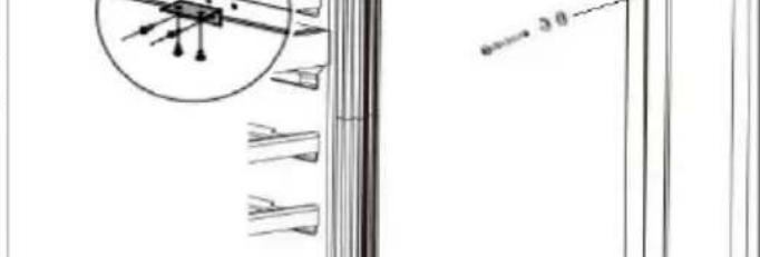

natural_image
Pure technical line drawing of a structural frame with mounting holes and diagonal braces (no text or symbols)
natural_image
Technical line drawing of a window frame with ventilation grilles and a 20-degree angle标注 (no text or symbols beyond measurement)
natural_image
Pure technical line drawing of a mechanical assembly without any text, numbers, or symbols
natural_image
Mechanical assembly diagram showing a spring-loaded component with directional arrow (no text or symbols)
natural_image
Mechanical assembly diagram showing a spring-loaded component inserted into a housing (no text or symbols)natural_image
Technical line drawing of a multi-stage bottle arrangement in a rack, showing internal structure and packaging (no text or symbols)| WINE COOLER | |
| Model | RCW-4G |
| Climatic category | N, SN, ST |
| Protective Class | I |
| Voltage/Frequency | 230V~750Hz |
| Current | 0.7A |
| Energy Consumption | 0.400kWh/24h |
| Refrigerant | 960Ca (26g) |
| Volume | 13TL |
| Weight | 451g |
| Production Year | 2012 |
| Serial No. | 637720220001 |
10012507
| WINE COOLER | ||
| Model | RCWI-6G | 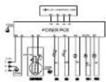 |
| Climatic category | N, 5T | |
| Protective Class | I | |
| Voltage/Frequency | 230V/-150Hz | |
| Current | L5A | |
| Energy Consumption | 0.405kAh/24h | |
| Insulation Blowing Gas | Cyclopentane | |
| Refrigerant | R600a (50g) | |
| Volume | 158L | |
| Weight | 47.5kg | |
| Production Year | 2022 | |
| Serial No. | G37720220131 | |
10012508
| WINE COOLER | 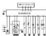 | |
| Model | RCWi-7G | |
| Climatic category | N, ST | |
| Protective Class | I | |
| Voltage/Frequency | 230V~/50Hz | |
| Current | 0.4A | |
| Energy Consumption | 0.373kWh/24h | |
| Insulation Blowing Gas | Cyclopentane | |
| Refrigerant | R600s (20g) | |
| Volume | 56L | |
| Weight | 28.5ig | |
| Production Year | 2022 | |
| Serial No. | 637720220D61 | expondo.com |
For the disposal of the device please consider and act according to the national and local rules and regulations.
CONTACT
expondo Polska sp. z o.o. sp. k.
- General Description
- CAREFULLY READ AND UNDERSTAND THIS MANUAL BEFORE PROCEEDING.
- Explanation of symbols
- Safety of use
- Electrical safety
- Safety in the workplace
- Personal safety
- Safe use of the unit
- Rules of use
- Description of the unit
- Preparation for operation
- POSITIONING OF THE UNIT
- BEFORE INITIAL USE
- ASSEMBLY OF THE UNIT
- Working with the unit
- STARTING THE UNIT / TEMPERATURE SETTINGS
- MODEL RCWI-4G
- MODEL RCWI-6G / RCWI-7G
- UNIT OPERATION (RCWI-4G / RCWI-6G / RCWI-7G MODEL)
- BOTTLE STORAGE
- Cleaning and maintenance
- DISPOSAL OF USED UNITS.
- APPARATETS PLACERING
- CONTACT
Brand : Royal Catering
Model : RCWI-6G
Category : Wine cellar