Startronic Supercap 12/24 V - Power bank GYS - Free user manual and instructions
Find the device manual for free Startronic Supercap 12/24 V GYS in PDF.


| Product Type | Portable supercapacitor battery booster |
| Brand | GYS |
| Model | Startronic Supercap 12/24 V |
| Nominal voltages | 12 V and 24 V (2 x 12 V) |
| Input voltage | DC 7 V to 32 V |
| Number of supercapacitors | 10 x 900 Farads |
| Recharge time from vehicle battery | 12 V: ≤ 5 min; 24 V: ≤ 2 min |
| Recharge time with engine running | 12 V: ≤ 3 min; 24 V: ≤ 2 min |
| Operating temperature | -40 °C to 65 °C |
| Main functions | 12 V/24 V vehicle starting, standard mode, Bypass mode, reverse polarity protection, digital display |
| Display | Digital with charge, voltage indicators and icons |
| Buttons | Voltage selector, On/Off, Bypass |
| Power supply | Via vehicle battery (supercapacitor recharge) |
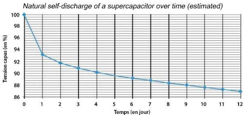
| Self-discharge | Significant: loss of approximately 13% in 10 days |
| Maintenance | Clean with a dry cloth, do not use solvents |
| Safety | Short-circuit, reverse polarity, overheating protection |
| Warranty | 2 years (parts and labor) |
| Standards compliance | CE, EAC, UKCA, CMIM |
| Device class | Class III |
Frequently Asked Questions - Startronic Supercap 12/24 V GYS
User questions about Startronic Supercap 12/24 V GYS
0 question about this device. Answer the ones you know or ask your own.
Ask a new question about this device
Download the instructions for your Power bank in PDF format for free! Find your manual Startronic Supercap 12/24 V - GYS and take your electronic device back in hand. On this page are published all the documents necessary for the use of your device. Startronic Supercap 12/24 V by GYS.
USER MANUAL Startronic Supercap 12/24 V GYS
natural_image
Technical line drawing of a mechanical device with internal components and mounting brackets (no text or symbols)| FR | 2-9 / 51-52 |
| EN | 9-15 / 51-52 |
| DE | 16-22 / 51-52 |
| ES | 23-29 / 51-52 |
| RU | 30-36 / 51-52 |
| NL | 37-43 / 51-52 |
| IT | 44-50 / 51-52 |
Réglementation :
natural_image
Technical line drawing of a device casing with control panel and display (no text or symbols)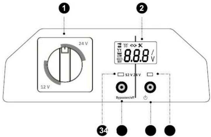
This user manual includes operation instructions, and the safety precautions to be followed by the user. Please read it carefully before first use and keep it for future reference. These instructions must be read and fully understood before use. Do not carry out any alterations or maintenance work that is not directly specified in this manual. The manufacturer is not liable for any injury or damage caused due to non-compliance with the instructions featured in this manual. If there is any issue or uncertainty, please consult a qualified individual to operate the equipment correctly. This machine should only be used for starting operations comprised within the limits indicated on the machine and in the instruction manual. The safety instructions must be followed. The manufacturer cannot be held responsible in the event of improper or dangerous use.
This unit can be used by children aged eight or over, by people with reduced physical, sensory or mental capabilities as well as by those with a lack of experience or knowledge. However, these aforementioned persons must be properly supervised and they must have read and understood the user instructions, alongside having been made aware of the risks. Children must not play with the product. Cleaning and maintenance should not be performed by an unsupervised child.
Do not use to charge domestic batteries or non rechargeable batteries.
Do not cover the device.
Do not place the unit near a heat source/direct sunlight and durably high temperatures (above 60 °C)
Risk of explosion or acid splash if the clamps are short-circuited or if the 12 V booster is connected to a 24 V vehicle.
Protect the battery's electrical contact surfaces against short-circuits
Do not leave a battery being charged unattended for long periods of time.
Never start a vehicle without a battery.

Connection / disconnection :
- Always ensure the Red clamp is connected to the «+» battery terminal first. If it is necessary to connect the black clamp to the chassis of the vehicle, make sure it is a safe distance from the battery and the fuel/exhaust pipe.
- After starting, disconnect the booster. Remove the connection to the chassis first, followed by the battery connection, in the order shown.

Power supply:
- Class III device.
Maintenance:
- Maintenance should only be carried out by a qualified person.
- Do not use solvents or any agressive cleaning products.
- Clean the surfaces of the unit with a dry cloth.

Regulations:
• Equipment complies with European directives
- The Declaration of Conformity is available on our website.
- EAC conformity mark (Eurasian Economic Community).
- This equipment conforms to UK requirements.
- The UK Declaration of Conformity is available on our website (see cover page).
- This device complies with Moroccan standards.
- The C_ (CMIM) declaration of conformity is available on our website.

Disposal:
- This product should be disposed of in an appropriate recycling facility. Do not dispose of in domestic waste.
• This product should be recycled appropriately


INTERFACE
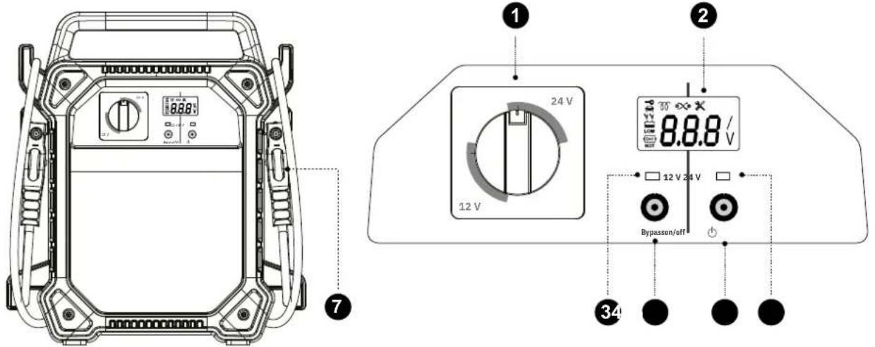
| 1. Voltage selector 5. «Bypass» button | |
| 2. Display 6. «On/OFF» button | |
| 3. 12V LED 7. Starter cables | |
| 4. 24V LED |
GENERAL DESCRIPTION
This booster incorporates supercapacitors and is designed for vehicles fitted with a 12 V or 24 V (2 x 12 V) battery. It uses the residual voltage from the battery in the faulty vehicle in order to charge itself, and then start the vehicle in just a few seconds.
DISCHARGE AND RECHARGE PROPERTIES OF SUPERCAPACITORS
Supercapacitor properties:
- they have a high level of natural self-discharge (see graph below).
- they can accept a high charging current and can therefore be recharged very quickly (eg: on the engine of a running vehicle).
line
| Temps (en jour) | Tension capas (en %) | | --------------- | -------------------- | | 0 | 100 | | 1 | 93 | | 2 | 92 | | 3 | 91 | | 4 | 90 | | 6 | 89 | | 7 | 88.5 | | 8 | 88 | | 9 | 87.5 | | 10 | 87.5 | | 11 | 87 | | 12 | 86.5 |
It is not necessary to keep a supercapacitor booster on charge.
It is not necessary to charge a supercapacitor booster one or more days before it is needed, as it may become partially or totally discharged during this period (graph).
The main advantages of a supercapacitor booster are that it requires no maintenance (no reduction in performance) and that it can be recharged very quickly, in just a few seconds/minutes before use.
USE IN STANDARD MODE
Supercapacitor charging
The STARTRONIC recharges in a matter of seconds by connecting directly to the 12 V or 24 V battery (2 x 12 V) of the vehicle you intend to start.
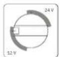
Make sure the voltage selector is correctly set to 12 V or 24 V depending on the voltage of the battery to be started.
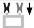
Connect the STARTRONIC clamps to the battery of the affected vehicle, observing the correct polarity.
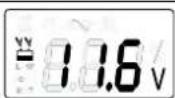
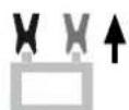
The STARTRONIC will automatically light up and indicate the voltage measured across the terminals of the battery terminals of the vehicle (an icon of a battery with clamps will appear on the display).
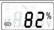
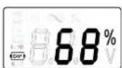
Press the button. The STARTRONIC will start charging. The charge percentage of the supercapacitors will appear on the screen (a supercapacitor icon will be shown on the display).
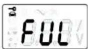
The STARTRONIC will display «FUL» when the supercapacitors are 100% charged. It is ready to start (the ignition key icon appears on the display).

If one or both clamps are disconnected, the STARTRONIC automatically goes into standby mode.

If the STARTRONIC is unable to recharge the supercapacitors, this means that the battery voltage is too low (12 V: < 7 V, 24 V: < 14 V). Refer to «Bypass» mode.
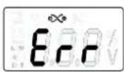
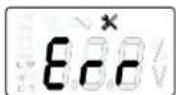
If the «Err» message appears, refer to the Errors section of this manual.
Starting the vehicle
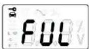
Once the supercapacitors have been fully charged, STARTRONIC is ready for starting.

Start the vehicle you wish to recover as quickly as possible, before the capacity of the STARTRONIC is transferred to the battery of the vehicle.
Optional - if it is necessary to repeat the starting process
Once you have started the engine, press and wait for the STARTRONIC to recharge with the engine running, until the digital display shows «FUL». It will then be ready to use again.
Disconnect the STARTRONIC clamps from the vehicle. Wind the cables up and position the clamps in the designated holder.

If the vehicle you are trying to recover still fails to start after 2 attempts, then the fault is probably not linked to the battery, or the booster is not adapted to the vehicle type. Investigate the real cause of the fault before attempting to start again.

If the first attempt is not successful, the STARTRONIC will become discharged. Recharge the STARTRONIC before trying again. Please see «SUPERCAPACITOR CHARGING».
USE IN «BYPASS» MODE
If the STARTRONIC has not been able to recharge from the battery of the vehicle you want to start, because the voltage is too low: < 7 V at 12 V and < 14 V at 24 V. The «Bypass» mode must be used.
Charging the supercapacitors
| Make sure the voltage selector is correctly set to 12 V or 24 V depending on the voltage of the battery used. | |
| Connect the STARTRONIC clamps to a battery which is not connected to the vehicle you wish to start. | |
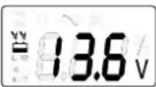 | The STARTRONIC will automatically light up and indicate the voltage measured across the terminals of the vehicle's battery. |
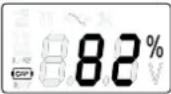 | Press the button. The STARTRONIC will start charging. The charge percentage of the supercapacitors appears on the screen. |
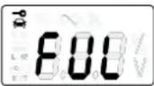 | The STARTRONIC will display «FUL» when the supercapacitors are 100% charged. It is ready to perform a start. |
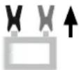 | Disconnect the STARTRONIC clamps from the vehicle. |

Do not charge the device in a running vehicle. The high voltage generated by the alternator (> 14 V) can disrupt the supercapacitor charging process.
Starting in «Bypass» mode
| When the booster is removed from the vehicle, there is a potential risk of damaging the ECUs if the battery is extremely sulphated and/or the cells are damaged.FOLLOW THE INSTRUCTIONS BELOW VERY CAREFULLY. | |
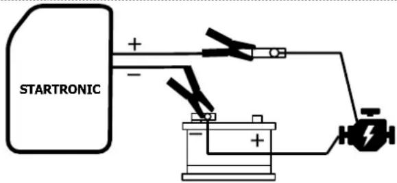 | Unplug the (+) connector from your battery's terminal and connect the STARTRONIC's red clamp (+) to it.Connect the black clamp (-) to the (-) terminal on your battery. |

Check the connections before proceeding to the next step. DO NOT REVERSE THE POLARITY (the protection is disabled).

Press the 📁 button.
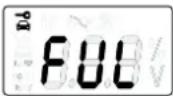
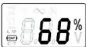
The digital display indicates the capacity of the STARTRONIC.

Bypass
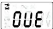
Press the «Bypass» button for 3 s to force the vehicle you wish to recover to start.
The digital display shows «OVE» meaning that «Bypass» mode is active for 30 seconds.

Start the vehicle you are recovering within the allotted time, before the capacity of the STARTRONIC is transferred to the major consumers in the vehicle.
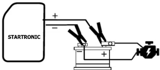
Refit the assembly: connect the red (+) clip to the (+) terminal on the battery.
Optional - if it is necessary to repeat the starting process
Once you have started the engine, press and wait for the STARTRONIC to recharge with the engine running, until the digital display shows «FUL». It will then be ready to use again.
When the STARTRONIC is switched off: Disconnect the STARTRONIC clamps from the vehicle. Wind the cables up and position the clamps in the designated holder.
ERRORS
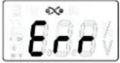 | Polarity reversal |
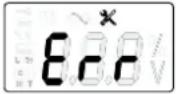 | 1 The booster is unable to recharge its supercapacitors. |
| 2 The connected battery voltage is 24 V and the booster is in 12 V mode. | |
| 3 The voltage of the supercapacitors is too low. The booster cannot launch «Bypass» mode. | |
| 4 The output voltage (12 V / 24 V) is altered while the booster is in operation, either when on charge or during starting. | |
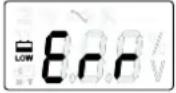 | Abnormal voltage at the terminals of the clamps (recharged by the alternator, for example). The booster is unable to recharge its supercapacitors. |
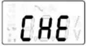 | 1 The voltage of the connected battery is 12 V and the booster is in 24 V mode. Check the battery before continuing. |
| 2 The booster is in 24 V mode for a 24 V battery connected, but whose voltage is too low (e.g. 12 V). Check the battery before continuing. |
TECHNICAL INFO
| 12 V 24 V | ||
| Input | DC 7V-DC 32V | |
| Number of supercapacitors 10 x 900 Farads | ||
| Supercapacitor recharge time- on the battery of the vehicle being started ≤ 5 min ≤ 2 min- on the battery of a running vehicle ≤ 3 min ≤ 2 min | ||
| Working temperature - 40°C to 65°C | ||
WARRANTY
The warranty covers any defects or manufacturing faults for two years from the date of purchase (parts and labour).
The warranty does not cover:
- Any other damage caused during transport.
- The general wear and tear of parts (i.e. : cables, clamps, etc.).
- Incidents caused by misuse (incorrect power supply, dropping or dismantling).
- Environment-related faults (such as pollution, rust and dust).
In the event of a breakdown, please return the item to your distributor, along with:
- a dated proof of purchase (receipt or invoice etc.).
- a note explaining the malfunction.
SICHERHEITSHINWEISE

natural_image
Technical line drawing of a device casing with control panel and display (no text or symbols)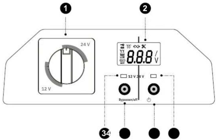
natural_image
Technical line drawing of a device casing with control panel and display (no text or symbols)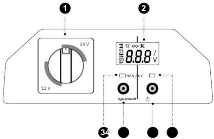
| 1. Selector de tensión 5. Botón "Bypass" | |
| 2. Pantalla 6. Botón "On/OFF" | |
| 3. LED 12 V 7. Cables de arranque | |
| 4. LED 24 V |
DESCRIPCIÓN GENERAL
natural_image
Technical line drawing of a device casing with control panel and display (no text or symbols)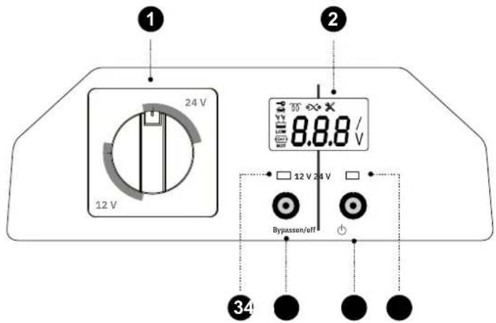
natural_image
Technical line drawing of a device casing with control panel and display (no text or symbols)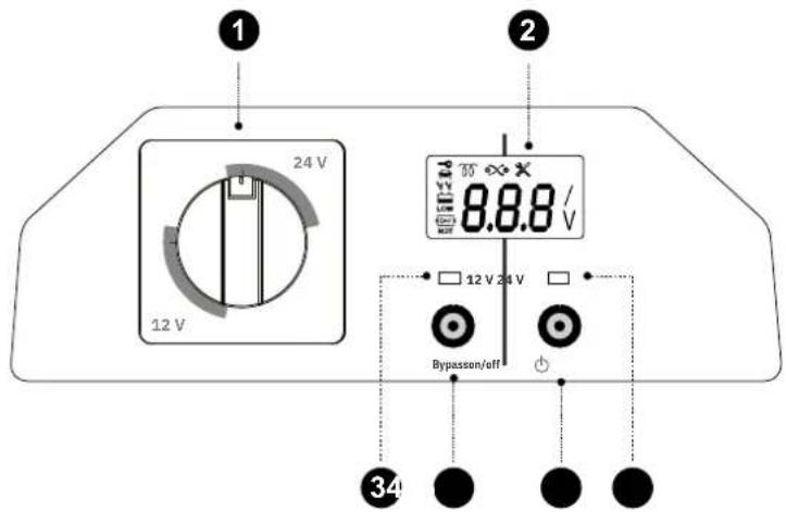
| 1 | Commutateur 12/24V + bouton / 12/24V switch + button / 12/24V Schalter + Taste / Interruptor 12/24V + botón / Переключатель 12/24 B + кнопka / 12/24V schakelaar + knop / Interruttore 12/24V + pulsante | SAV07015 |
| 2 | Jeu de câbles pinces (rouge et noir) / Set of clamps + cables (red and black) / Satz Klemmen + Kabel (rot und schwarz) / Juego de abrazaderas + cables (rojo y negro) / Комплект зажимов + кабели (красный и черный) / Set klemmen + kabels (rood en zwart) / Set di morsetti + cavi (rosso e nero) | SAV07014 |
| 3 | Carte afficheur / Display board / Karte anzeigen / Tarjeta de visualización / Дисплейная карта / Weergavekaart / Scheda display | SAV04023 |
| 4 | Carte convertisseur / Converter board / Wandlerplatine / Tarjeta convertidora / Плата преобразователя / Printplaat converter / Scheda convertitore | SAV04024 |
| 5 | Contacteur de puissance / Power contactor / Leistungsschütz / Contactor de potencia / Силовой контактор / Stroomschakelaar / Contattore di potenza | SAV07016 |
GYS France
Siège social / Headquarter


- Réglementation :
- Connection / disconnection :
- Power supply:
- Maintenance:
- Regulations:
- Disposal:
- GENERAL DESCRIPTION
- DISCHARGE AND RECHARGE PROPERTIES OF SUPERCAPACITORS
- Supercapacitor properties:
- USE IN STANDARD MODE
- Supercapacitor charging
- Starting the vehicle
- USE IN «BYPASS» MODE
- WARRANTY
- SICHERHEITSHINWEISE
- DESCRIPCIÓN GENERAL
- GYS France
Brand : GYS
Model : Startronic Supercap 12/24 V
Category : Power bank