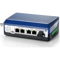
cnReach N550 - Wi-Fi Router Cambium Networks - Free user manual and instructions
Find the device manual for free cnReach N550 Cambium Networks in PDF.


| Product Type | Industrial Wi-Fi Router (point-to-point/multipoint radio module) |
| Brand | Cambium Networks |
| Model | cnReach N550 |
| Frequency Bands | 900 MHz (unlicensed), 450 MHz (licensed), 700 MHz, 220 MHz |
| Maximum Power (450 MHz) | 8 W (39 dBm EIRP) |
| Power Supply | 24 VDC via AC brick (NB-N500006B-US / NB-N500011B-GL) or DIN rail (NB-N500013A-GL) |
| Default IP Address | 192.168.0.3 |
| Default Credentials | admin / admin |
| Interfaces | 2 Ethernet 10/100 ports, 2 RJ-45 serial ports (including CLI), integrated analog/digital I/O |
| Compatible Antennas | Whip (0 dB gain), Yagi (6.5 / 10 dBd), Omnidirectional (multiple models) |
| Mounting | Horizontal surface or DIN rail (option NB-N500004A-US) |
| Management Software | cnMaestro (cloud or on-premises) |
| Planning Tool | LINKPlanner (free, Google Earth integration) |
| RF Safety | Minimum distance of 2.52 m (450 MHz EU) |
| Environmental Protection | Must be installed in a weatherproof enclosure (indoor or NEMA enclosure) |
| Connectivity | HTTPS, CLI (115200 8N1), SNMP, VLAN |
| Supplied Accessories | Power and I/O connectors, DB9-RJ45 adapter |
| Spare Parts | Connectors (NB-N500002A-US, NB-N500003A-US), power supplies, antennas (full references in the manual) |
| Software Version | System 01-31 (SE firmware cn-EBX.5.2.17e, radio firmware per band) |
| Radio Specifications | Single or dual modules, with or without integrated I/O, narrowband or broadband |
Frequently Asked Questions - cnReach N550 Cambium Networks
User questions about cnReach N550 Cambium Networks
0 question about this device. Answer the ones you know or ask your own.
Ask a new question about this device
Download the instructions for your Wi-Fi Router in PDF format for free! Find your manual cnReach N550 - Cambium Networks and take your electronic device back in hand. On this page are published all the documents necessary for the use of your device. cnReach N550 by Cambium Networks.
USER MANUAL cnReach N550 Cambium Networks

Cambium Networks™




QUICK START GUIDE
cnReach™ N500

Content
ENGLISH (UK, IE, NO) 6
QUICK REFERENCE....6
Current Software Version....6
Default Login Information....6
Accessing the User Interface 6
Contacting Cambium Networks....7
CNREACH SYSTEM COMPONENTS 8
Radio Module 8
Accessories 9
Obtaining an Unknown IP Address....15
MOUNTING THE CNREACH MODULE....19
DEPLOYMENT PROCESS....20
Planning....20
LINKPlanner....20
Site Survey....20
Installation....20
Troubleshooting....21
PRODUCT LEAFLET - 450 MHZ PRODUCT ONLY 22
CZECH (CZ) 23
STRUČNÝ PŘEHLED 23
Troubleshooting....157
PRODUKTBLATT - NUR FÜR 450 MHZ-VARIANTE....158
English (UK, IE, NO)
Quick Reference
Current Software Version
This guide reflects system release 01-31 containing the following software versions which can be downloaded from the Cambium Networks support website:
https://support.cambiumnetworks.com/files/n500/
| OS firmware: | cn-EBX.5.2.17e_update |
| Radio firmware: | rf_1.48.17487-400 (450 MHz FCC models) |
| rf_1.48.17487-400g2 (450 MHz ETSI RED models) | |
| rf_1.48.17487-700g2 | |
| rf_1.48.17487-900 | |
| rf_1.48.17487-200 | |
| Optional Software Modules: | cs-5.2.17d_module (for high-availability 1+1 station) |
| wr-5.2.17d_module (for wire replacement feature) |

Attention Note that there are different radio firmware files depending on the band of the radio. The band is denoted in the filename (eg. 450 = 450 MHz radios; 900 = 900 MHz).
Default Login Information
Default IP address: 192.168.0.3
Default Username: admin
Default Password: admin
Please refer to the Obtaining an Unknown IP Address section in the Quick Start Guide if you cannot access the User Interface.
Accessing the User Interface
The User Interface is accessed by initiating a secure HTTPS connection (or HTTP connection depending on the radio's configuration) from a Web Browser, via direct Ethernet port connection or active radio link.
- Ensure that your laptop is configured with an IP address on the same subnet as the default IP address.
- Type https://
in the URL box; i.e. https://192.168.0.3 - If this is the first time attempting to connect via https the browser may prompt you regarding privacy. Certificates are usually associated with fully-qualified domain names and not individual IP addresses, so this prompt is completely normal.
Contacting Cambium Networks
Support website: http://support.cambiumnetworks.com/
Main website: http://www.cambiumnetworks.com
Sales enquiries: solutions@cambiumnetworks.com
Telephone number list: http://www.cambiumnetworks.com/contact
Address: Cambium Networks
Suite 360
3800 Golf Road
Rolling Meadows, IL 60008
cnReach System Components
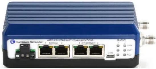
Radio Module
A cnReach system consists of the following components:
- Radio modules available in multiple frequency bands; access to spectrum depends on geographic location and your access to the spectrum to be used:
■ Frequencies
• Licensed and unlicensed 900 MHz
- FCC models
- Australia models
• Licensed 757-758 and 787-788 MHz for United States only
- Licensed 450 MHz
- ETSI RED models (406 - 470 MHz)
– US/FCC models (406-430 and 450-470 MHz)
- Licensed 220 MHz (217 to 222 MHz) for United States only
■ Single or dual radio modules
■ With or without built-in analog/digital I/O
- Accessories
■ 24 VDC Power supplies (AC input 'bricks' or DIN-rail mount AC supplies)
■ Yagi, Omni and 'whip' antennas
- Yagi and Omni antennas can be purchased with or without an installation kit that includes cabling, surge suppression, grounding and weather-proofing
■ DIN-Rail mounts
■ DB-9 to RJ-45 adaptor for accessing the serial port on the radio
- Spare power and I/O connectors
LINKPlanner
■ A planning and deployment tool made available by Cambium Networks
■ Easy-to-use graphical interface that integrates with Google Earth or Google Maps
■ Provides predictions of link performance and reliability
■ Provides a bill of materials
■ Provides an installation report to simplify the installation and alignment of cnReach radios
■ LINKPlanner can be downloaded at no cost from the Cambium Networks website at http://www.cambiumnetworks.com/linkplanner
- cnMaestro
■ Full life-cycle network management solution for networks based on Cambium Networks equipment.
■ Supports on-boarding, performance, fault and configuration management in a single pane-of-glass
■ Available in both cloud and on-premises versions.
- cnReach radios are often installed in NEMA enclosures as cnReach radios and power supplies are not designed for deployment in water or dust environments.
Accessories
IO Expander
The IO expander is a cnReach module with no radios. It can be used to add Serial or Analog/Digital I/O to a broadband network or additional I/O to a narrowband network. It is managed and configured in the same way as a cnReach radio from a networking and management perspective.
| NB-N500001A-US | N500 IO Expander |
| NB-N500002A-US | N500 Power Connector, Spare |
| NB-N500003A-US | N500 IO Connector, Spare |
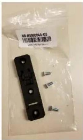
| NB-N500004A-US | N500 DIN Rail Mount |
| NB-N500005A-US | N500 RJ45-DB9 Adaptor |
| NB-N500013A-GL | Power Supply, AC to 24VDC, DIN RAIL MOUNT |
| NB-N500006B-US | N500 AC to 24 VDC Power Supply with US line cord |
| NB-N500011B-GL | N500 AC to 24 VDC Power Supply (no line cord) |
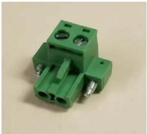
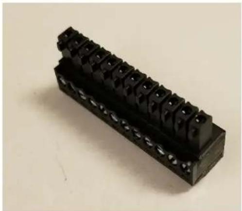
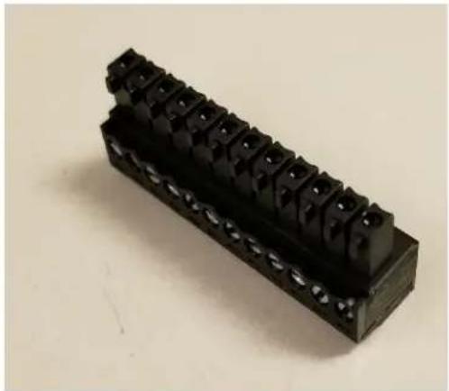
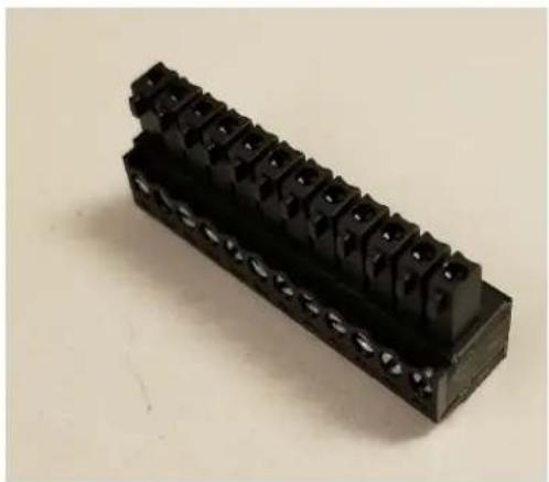
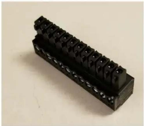
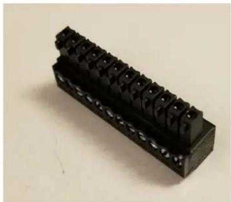
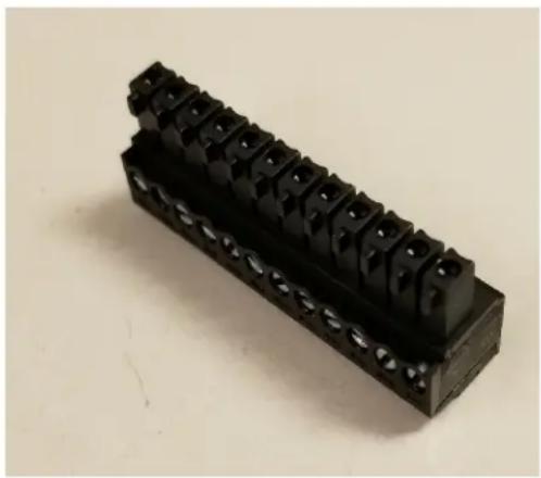
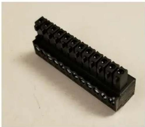
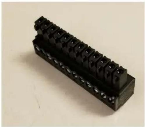
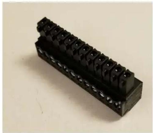
Each cnReach radio module ships with a power connector and an I/O connector. The model listed here are for spares purposes to replace lost or damaged connectors. Pictured below are the spare power connector and spare I/O connector.
DIN Rail Mount
The DIN Rail Mount allows for mounting the cnReach module on a standard DIN rail.
Power Supplies
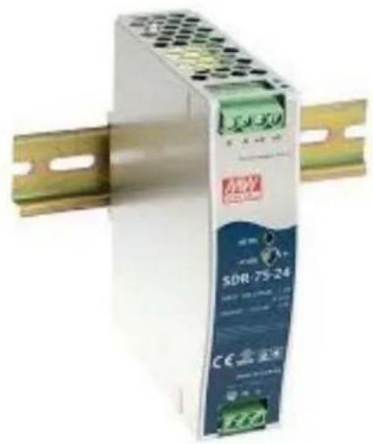
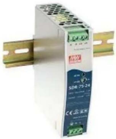
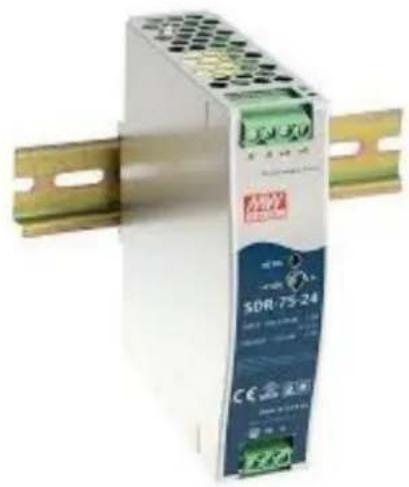
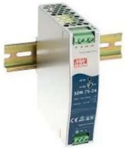
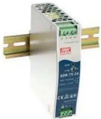
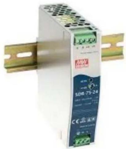
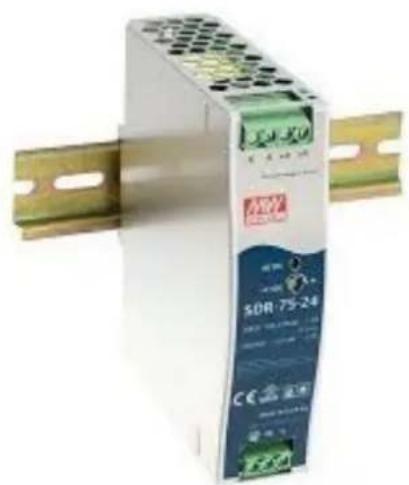
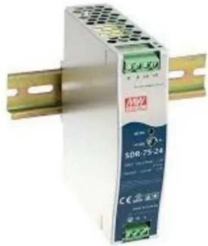
Cambium offers two power supplies for cnReach. The first is an AC brick useful for bench testing or temperature controlled environments. The second is a DIN rail supply that covers a wide temperature range and is mountable in a NEMA enclosure next to a cnReach DIN mounted radio.

Attention The DIN-rail supply does NOT come with a line cord. Also note the availability of the 'brick' supply without a line cord for import into countries using a non-U.S. style cord
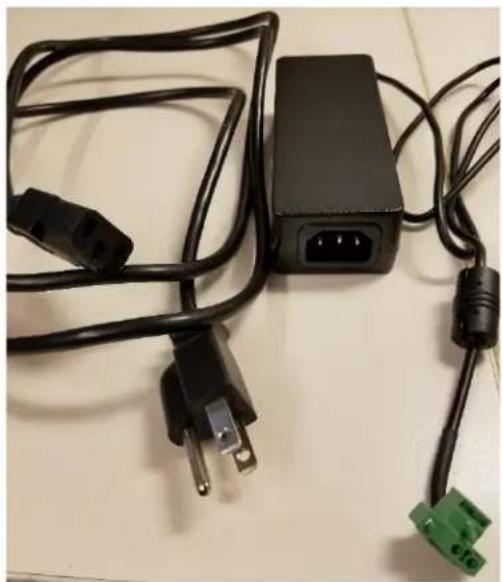
NB-N500006B-US
N500 AC to 24 VDC Power Supply with US line cord
NB-N500011B-GL
N500 AC to 24 VDC Power Supply (no line cord)
NB-N500013A-GL
Power Supply, AC to 24VDC, DIN RAIL MOUNT
Antennas
Cambium Networks offers a range of antenna options and installation kits to assist in the deployment of a complete system.
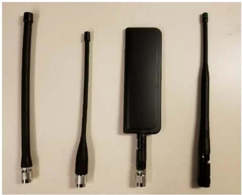
For bench testing and trials, a series of 'whip' low-gain omni antennas is available for each band.
| NB-N500008A-US | N500 900 MHz Whip Antenna |
| NB-N500009A-US | N500 700 MHz Whip Antenna |
| NB-N500010A-US | N500 450 MHz Whip Antenna |
| NB-N500012A-US | N500 220 MHz Whip Antenna |
These whip antennas generally net out to unity gain or close to 0 dB. Pictured below are the whip antennas from left to right (220 MHz, 450 MHz, 700 MHz and 900 MHz)
Note that the 220 MHz and 450 MHz whip antennas need to be trimmed to the correct length for optimal frequency matching. An instruction sheet is included with each antenna to indicate the correct length. Those instruction sheets are pictured below:
| FREQUENCY MHz | LENGTH (INCHES) |
| 135 | 7 7/8 |
| 140 | 7 5/8 |
| 145 | 7 1/4 |
| 150 | 7 |
| 155 | 6 3/4 |
| 160 | 6 1/2 |
| 165 | 6 5/16 |
| 170 | 6 1/8 |
| 175 | 6 |
| 220 | 4 5/8 |
| 225 | 4 1/2 |
CUTTING INSTRUCTIONS
- With cap removed, measure from the bottom of the connector to the appropriate length as determined by the cutting lengths supplied.
- Mark the antenna at the point of desired length.
- Cut the antenna
- Apply glue (crazy/super glue) to the top of the antenna and the cap.
- Place cap on antenna. Allow glue to dry completely.
| FREQUENCY (MHz) | LENGTH (Inches) |
| 400 | 7 3/4 |
| 410 | 7 1/2 |
| 420 | 7 1/8 |
| 430 | 7 |
| 440 | 6 3/4 |
| 450 | 6 1/2 |
| 460 | 6 3/8 |
| 470 | 6 1/8 |
| 480 | 6 |
| 490 | 5 7/8 |
| 500 | 5 3/4 |
| 510 | 5 5/8 |
| 520 | 5 1/2 |
CUTTING INSTRUCTIONS
- With cap removed, measure from the bottom of the connector to the appropriate length as determined by the cutting lengths supplied.
- Mark the antenna at the point of desired length.
- Cut the antenna.
- Apply glue (crazy/super glue) to the top of the antenna and the cap.
- Place cap on antenna. Allow glue to dry completely.
In addition to the whip antennas, Cambium provides a selection of Yagi antennas and an omni antenna for field deployments. Specification sheets for these antennas are available on the Cambium website.
Model # Cambium Description
| NB-N500020A-GL | Yagi Antenna, 900 MHz 6.5 dBd, Single Pol |
| NB-N500021A-GL | Yagi Antenna, 900 MHz 10 dBd, Single Pol |
| NB-N500022A-GL | Yagi Antenna, 700 MHz 10 dBd, Single Pol |
| NB-N500024A-GL | Yagi Antenna, 406-430 MHz 6.5 dBd, Single Pol |
| NB-N500025A-GL | Yagi Antenna, 406-430 MHz 10 dBd, Single Pol |
| NB-N500026A-GL | Yagi Antenna, 450-470 MHz 6 dBd, Single Pol |
| NB-N500027A-GL | Yagi Antenna, 450-470 MHz 10 dBd, Single Pol |
| NB-N500042A-GL | Yagi Antenna, 215-225 MHz, 6.5 dBd, Single Pol |
| NB-N500029A-GL | NB-N500029A-GL |
| NB-N500044A-GL | NB-N500044A-GL |
| NB-N500045A-GL | NB-N500045A-GL |
| NB-N500053A-GL | NB-N500053A-GL |
| NB-N500046A-GL | NB-N500046A-GL |
| NB-N500030A-GL | Yagi Antenna with Install Kit, 900 MHz 6.5 dBd, Single Pol |
| NB-N500031A-GL | Yagi Antenna with Install Kit, 900 MHz 10 dBd, Single Pol |
| NB-N500032A-GL | Yagi Antenna with Install Kit, 700 MHz 10 dBd, Single Pol |
| NB-N500034A-GL | Yagi Antenna with Install Kit, 406-430 MHz 6.5 dBd, Single Pol |
| NB-N500035A-GL | Yagi Antenna with Install Kit, 406-430 MHz 10 dBd, Single Pol |
| NB-N500036A-GL | Yagi Antenna with Install Kit, 450-470 MHz 6 dBd, Single Pol |
| NB-N500037A-GL | Yagi Antenna with Install Kit, 450-470 MHz 10 dBd, Single Pol |
| NB-N500052A-GL | Yagi Antenna with Install Kit, 215-225 MHz, 6.5 dBd, Single Pol |
| NB-N500041A-GL | Antenna Installation Kit, 50 foot |
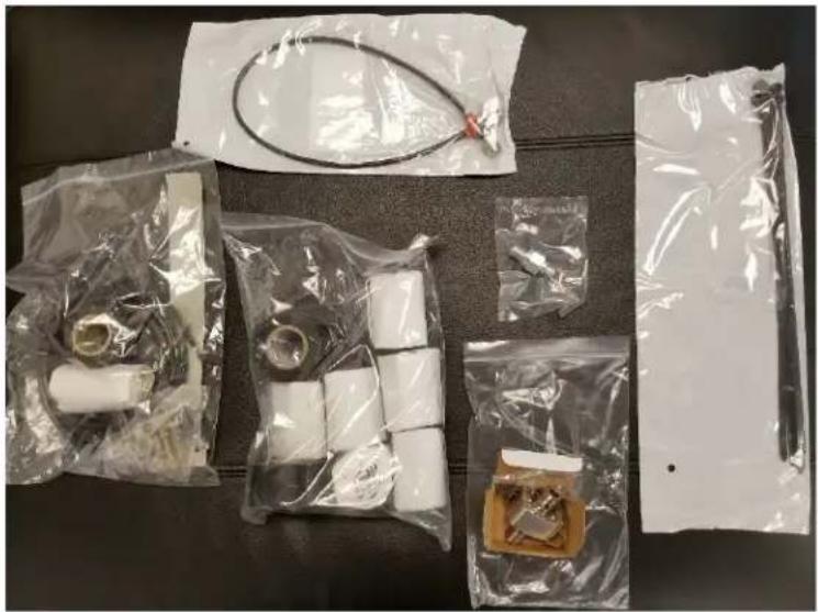
The Yagi antennas are available either stand-alone with a two-foot lead or with an integrated installation kit. For Yagis purchased with an installation kit, the antenna comes with the following items as shown in the picture below:
- Attached 25' cable
- Grounding kit
• Weatherproofing kit
• Bulk-head mount RF surge suppressor - Extra N-type connector (used in case installer wishes to shorten the 25 or 50 ft. drop cable.
• A two foot jumper cable (N-Type to TNC) - Zip ties
The omni antenna is available stand-alone. The NB-N500041A-GL installation kit has a fifty foot cable which is compatible with the omni for a more turn-key installation.
cnMaestro
cnReach can be managed by cnMaestro. cnMaestro is available in either an on-premises version or a cloud-based version (the cloud version will support cnReach by end of 2018).
More information about cnMaestro and software downloads are available on the Cambium Networks website at http://www.cambiumnetworks.com/linkplanner
Refer the cnMaestro documentation for installing and configuring the server. For configuring cnReach devices to interact with cnMaestro refer to Chapter 2: System Configuration.
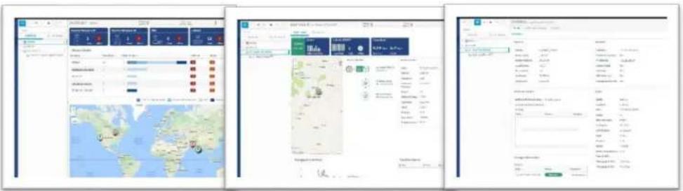
Some of the features available with cnMaestro specifically for use with cnReach are listed below:
| Deployment | Cloud-Hosted Web PortalCustomer-Hosted VMware OVABrowser-Based Web UI |
| Visualization | Full Visibility Across NetworkSupports ePMPTM, cnPilotTM, PMP, cnReachTM Multiple Product ViewsAccess and Backhaul ViewWireless LAN ViewIIoT View (for cnReach)Hierarchical Device TreeGoogle Maps IntegrationDevice AggregationsNetwork, Tower, Site, AP Group |
| Monitoring Inventory Table | |
| Dedicated Device DashboardsMaps and Map ModesStatistics and Trending | |
| Data and Reporting | Statistics Reports Exported in CSVRESTful Monitoring APIExport Tables in CSV or PDFGraphical Reports (Q4/17)Email Alarms (Q3/17)WebHooks API (Q4/17) |
| Administration | Multiple Administrators (up to 10)Role-Based AccessAdministrator Session Visibility |
| Onboarding and Provisioning | Zero-Touch OnboardingTemplate Configuration (Q4/17)Bulk Software Distribution (Q4/17)Software Update (Q4/17) |
| Troubleshooting and Forensics | Tower-to-Edge ViewStateful Alarms, EventsAlarm History |
| Security | Communication over SSLNo Inbound Internet AccessPlaced Outside of Traffic PathFirewall and NAT Friendly |
LINKPlanner
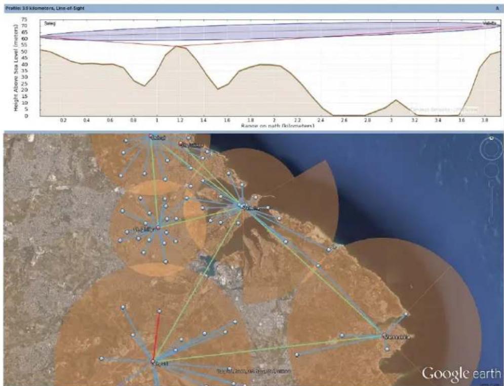
Designed for use with our point-to-point and point-to-multipoint solutions, LINKPlanner allows you to easily and quickly design networks for optimal deployment and cost effectiveness. LINKPlanner is a free, easy to use link-design tool that can be downloaded from the Cambium Networks support site. Some features available for supporting cnReach deployments include:
• Engineer a highly reliable wireless link even in challenging environments
- Plan and optimize a single link or multiple links simultaneously
- Plan an entire project including PTP and PMP products
• Perform calculations for both licensed and unlicensed products
• Automatically load path terrain profiles and environmental factors such as rain fade
- Display a comprehensive overview of your entire point-to-point wireless network via Google™ Earth
- Conduct “what if” scenarios based on geography, distance, antenna height and transmit power and instantly see the effects on performance
- Generate reports that validate projected performance and serve a time-saving deployment guidelines
• Create a bill of materials for PMP and PTP networks including accessories
Obtaining an Unknown IP Address
The IP address of the radio can be changed by the user at any time. It is also possible to assign different IP addresses to each interface; Eth1, Eth2, Radio1, Radio2 when using layer 3 routing. If the IP address of the radio is unknown, the CLI can be used to either discover the IP or default the radio back to the factory default IP address and configuration.

Attention Defaulting the radio via the CLI will also default the radio RF and radio network settings, which will bring down any active RF connections.
If your computer is on the same subnet as the default radio IP address and communications cannot be established, it's possible the IP address of the radio has changed. This is a common situation with previously-installed radios.

Note It is good practice to apply light colored electrical tape to the underside of the radio to track any IP address changes with a marker.
Use the following equipment to obtain the IP address you need:
- Serial to USB cable
• Standard CAT5 Ethernet cable
• cnReach N500 DB-9 to RJ-45 adapter
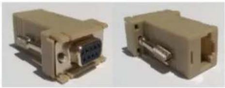
Connect the Serial to USB cable to the computer and install the drivers per the manufacturer instructions (unless the Operating System recognizes the device).
1 Note the COM Port number allocated to the device by the operating system.
2 Connect the RJ-45 to DB9 adapter to the DB9 Serial port on the Serial to USB cable.
3 Plug the CAT5 Ethernet cable into the RJ-45 to DB9 adapter.
4 Look at the SERIAL ports on the Enclosed radio. The SERIAL port that has the blinking Orange LED is the CLI port. Plug in the Cat5 Ethernet cable.

Attention! cnReach N500 radios use RJ-45 connectors for both Serial and Ethernet ports. This means it is possible to plug an Ethernet cable into a Serial port and vice versa.
5 Open a terminal emulator such as Teraterm, PuTTY or HyperTerminal and connect to the PC's COM Port at 115200 8N1.
6 Press Enter. You will be prompted to log in. Username: admin
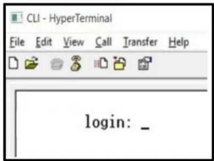
7 Type show ifconfig. The default Interface configuration (bridge) lists an IP address for VLAN1 only.
| > show ifconfig | |
| eth0 | Link encap:Ethernet HWaddr 70:F1:E5:00:00:00UP BROADCAST RUNNING MULTICAST MTU:1500 Metric:1RX packets:78331 errors:0 dropped:0 overruns:0 frame:0TX packets:54504 errors:0 dropped:0 overruns:0 carrier:0collisions:0 txqueuelen:1000RX bytes:6290948 (5.9 MiB) TX bytes:5780242 (5.5 MiB) |
| eth1 | Link encap:Ethernet HWaddr 70:F1:E5:01:5C:01UP BROADCAST MULTICAST MTU:1500 Metric:1RX packets:0 errors:0 dropped:0 overruns:0 frame:0TX packets:0 errors:0 dropped:0 overruns:0 carrier:0collisions:0 txqueuelen:0RX bytes:0 (0.0 B) TX bytes:0 (0.0 B) |
| eth1.1 | Link encap:Ethernet HWaddr 70:F1:E5:01:5C:01UP BROADCAST PROMISC MULTICAST MTU:1500 Metric:1RX packets:0 errors:0 dropped:0 overruns:0 frame:0TX packets:0 errors:0 dropped:0 overruns:0 carrier:0collisions:0 txqueuelen:0RX bytes:0 (0.0 B) TX bytes:0 (0.0 B) |
| eth2 | Link encap:Ethernet HWaddr 70:F1:E5:01:5C:01UP BROADCAST RUNNING MULTICAST MTU:1500 Metric:1RX packets:78331 errors:0 dropped:0 overruns:0 frame:0TX packets:54504 errors:0 dropped:0 overruns:0 carrier:0collisions:0 txqueuelen:0RX bytes:4802659 (4.5 MiB) TX bytes:5687626 (5.4 MiB) |
| eth2.1 | Link encap:Ethernet HWaddr 70:F1:E5:01:5C:01UP BROADCAST RUNNING PROMISC MULTICAST MTU:1500 Metric:1RX packets:78309 errors:0 dropped:0 overruns:0 frame:0TX packets:54503 errors:0 dropped:0 overruns:0 carrier:0collisions:0 txqueuelen:0RX bytes:4801633 (4.5 MiB) TX bytes:5687584 (5.4 MiB) |
| lo | Link encap:Local Loopbackinet addr:127.0.0.1 Mask:255.0.0.0UP LOOPBACK RUNNING MTU:16436 Metric:1RX packets:179 errors:0 dropped:0 overruns:0 frame:0TX packets:179 errors:0 dropped:0 overruns:0 carrier:0collisions:0 txqueuelen:0RX bytes:1023108 (999.1 KiB) TX bytes:1023108 (999.1 KiB) |
| rad1 | Link encap:Ethernet HWaddr 70:F1:E5:01:3A:F2UP BROADCAST RUNNING MULTICAST MTU:1500 Metric:1RX packets:86289 errors:0 dropped:0 overruns:0 frame:0TX packets:110240 errors:0 dropped:0 overruns:0 carrier:0collisions:0 txqueuelen:500RX bytes:7909518 (7.5 MiB) TX bytes:8173919 (7.7 MiB) |
| rad1.1 | Link encap:Ethernet HWaddr 70:F1:E5:01:3A:F2UP BROADCAST RUNNING PROMISC MULTICAST MTU:1500 Metric:1RX packets:86289 errors:0 dropped:0 overruns:0 frame:0TX packets:110240 errors:0 dropped:0 overruns:0 carrier:0collisions:0 txqueuelen:0RX bytes:6701472 (6.3 MiB) TX bytes:8173919 (7.7 MiB) |
| vlan1 | Link encap:Ethernet HWaddr 70:F1:E5:01:3A:F2inet addr:192.168.0.3 Bcast:192.168.0.255 Mask:255.255.255.0UP BROADCAST RUNNING MULTICAST MTU:1500 Metric:1RX packets:116234 errors:0 dropped:0 overruns:0 frame:0TX packets:82339 errors:0 dropped:0 overruns:0 carrier:0collisions:0 txqueuelen:0RX bytes:8000170 (7.6 MiB) TX bytes:6196725 (5.9 MiB) |
8 If the radio configuration is routed, it is possible for each interface to have a unique IP address. This time, show ifconfig will return the IP address of each physical interface.
9 The User Interface can be accessed at either the Eth1/Eth2 interface IP via a direct connection to that interface.

Note The Laptop/PC should be given a fixed IP address on the same subnet as the connected interface in order to establish Ethernet communications.
> show ifconfig
eth0 Link encap:Ethernet HWaddr 70:F1:E5:00:00:00
UP BROADCAST RUNNING MULTICAST MTU:1500 Metric:1
RX packets:79710 errors:0 dropped:0 overruns:0 frame:0
TX packets:55566 errors:0 dropped:0 overruns:0 carrier:0
collisions:0 txqueuelen:1000
RX bytes:6418040 (6.1 MiB) TX bytes:5891577 (5.6 MiB)

eth1 Link encap:Ethernet HWaddr 70:F1:E5:01:5C:D1
inet addr:192.168.1.3 Bcast:192.168.1.255 Mask:255.255.255.0
UP BROHDCAST MULTICAST MTU:1500 Metric:1
RX packets:0 errors:0 dropped:0 overruns:0 frame:0
TX packets:0 errors:0 dropped:0 overruns:0 carrier:0
collisions:0 txqueuelen:0
RX bytes:0 (0.0 B) TX bytes:0 (0.0 B)

eth2 Link encap:Ethernet HWaddr 70:F1:E5:01:5C:D1

inet addr:192.168.2.3 Bcast:192.168.2.255 Mask:255.255.255.0
UP BROHDCAST RUNNING MULTICAST MTU:1500 Metric:1
RX packets:79710 errors:0 dropped:62 overruns:0 frame:0
TX packets:55566 errors:0 dropped:0 overruns:0 carrier:0
collisions:0 txqueuelen:0
RX bytes:4903550 (4.6 MiB) TX bytes:5797191 (5.5 MiB)

lo Link encap:Local Loopback
inet addr:127.0.0.1 Mask:255.0.0.0
UP LOOPBACK RUNNING MTU:16436 Metric:1
RX packets:200 errors:0 dropped:0 overruns:0 frame:0
TX packets:200 errors:0 dropped:0 overruns:0 carrier:0
collisions:0 txqueuelen:0
RX bytes:1145456 (1.0 MiB) TX bytes:1145456 (1.0 MiB)

rad1 Link encap:Ethernet HWaddr 70:F1:E5:01:3A:F2
inet addr:10.10.10.1 Bcast:10.10.10.255 Mask:255.255.255.0
UP BROHDCAST RUNNING MULTICAST MTU:1500 Metric:1
RX packets:87269 errors:0 dropped:17 overruns:0 frame:0
TX packets:111408 errors:0 dropped:0 overruns:0 carrier:0
collisions:0 txqueuelen:500
Mounting the cnReach Module
The cnReach module can be placed on a horizontal surface or onto a DIN-Rail with option DIN-rail mount option. cnReach radios MUST be installed in weather-proof cabinet or indoors. cnReach modules are not meant for outdoor deployments.

Warning
Ensure that personnel are not exposed to unsafe levels of RF energy. The units start to radiate RF energy as soon as they are powered up.
Observe the following guidelines:
Never work in front of the antenna when the cnReach module is powered.
Always remove power from the cnReach module before connecting or disconnecting the drop cable the antenna.
Deployment Process
Successful network deployments are those that are installed predictably, perform well over time and recover from unexpected conditions quickly. Our experience troubleshooting networks taught us to plan, install and troubleshoot networks with the considerations listed below. Follow these steps to deploy a successful network.
Planning
- Understand customer's application and required network throughput. This is especially important when working with narrow-band channels on licensed spectrum. Take into account the polling cycles and the sizes of each poll especially when planning PMP networks.
- Test radios on the bench with desired equipment before first deployment. This is especially important when interfacing with serial or general-purpose IO equipment to confirm wiring diagrams, cables and cnReach module settings.
• Perform a path study for each link using Cambium Networks LINKPlanner. - Plan radio settings to achieve desired network throughput with consideration of expected signal strength, RF noise and overlapping networks.
• Perform a Site Survey to sample in-band noise levels. - Prepare equipment list that includes radios, radio accessories, cables, connectors, adapters, antennae, towers/poles, brackets, etc.
LINKPlanner
- The Cambium Networks LINKPlanner software and user guide may be downloaded from the support website:
http://www.cambiumnetworks.com/linkplanner
- LINKPlanner imports path profiles and predicts data rates and reliability over the path. It allows the system designer to try different antenna heights and RF power settings. It outputs an installation report that defines the parameters to be used for configuration, alignment and operation. Use the installation report to compare predicted and actual link performance.
Site Survey
A site survey involves using a spectrum analyzer or alternative spectrum tool to check in-band noise levels at the site.
- Cambium Networks considers this an important step when deploying standard networks since the in-band noise levels can be factored into the network design.
- Other aspects of a site survey include sweeping any existing installed coaxial transmission line, jumpers, surge suppressors and antennas for Return Loss or VSWR.
• Identifying possible causes of interference with co-located systems.
Installation
- Use compass to align antennae to magnetic azimuth as recommended by the LINKPlanner installation report
- Fine-tune the alignment by monitoring the results of the RF Ping diagnostic tool in the GUI to optimize the displayed RSSi value. This value can be compared to the predicted value in LINKPlanner. Any deviations from the LINKPlanner prediction should be justified before completing the installation.
• Properly torque all mechanical connections. -
Apply appropriate weatherproofing material to all exposed RF and electrical connections.
-
Measure noise floor with final hardware installed (i.e. antennae, cable) using radio or spectrum analyzer. The in-built spectrum analyzer can be used to scan the on-channel and neighboring channel noise levels.
• Compare actual received signal strength with expected signal strength from path study. - Perform throughput and latency tests before leaving site using the built-in RF Throughput diagnostic tool and/or a throughput tool such as iperf.
- Confirm successful customer data test before leaving site.
Troubleshooting
- Obtain customer success/fail statistics on SCADA master polls.
• Capture radio settings (via screen shot and/or the active configuration file).
• Capture radio statistics (via screen shot or other).
• Capture LAN statistics (via screen shot or other).
• Capture terminal server statistics (via screen shot or other).
• Perform noise measurement with radio and/or spectrum analyzer. - Obtain diagnostic slot capture from Access Point on problematic link.
- Sweep cable and antenna for loss with network analyzer (a.k.a site analyzer, cable and antenna tester).
Product Leaflet - 450 MHz product only
Installation & Operation

Installation and operation of this product is complex. Cambium therefore recommends professional installation and management of the system to ensure that operation complies with the regulations of the region where the product is installed. Please follow the instructions in this leaflet. Further guidance on PMP, PTP and BTB installation and operation is available in the product user guide, see link below.
The installer must have sufficient skills, knowledge and experience to perform the installation task and is responsible for:
- Familiarity with current applicable national regulations including radio regulations, electrical installation regulations, surge protection regulations and 'working at heights' regulations
• Installation in accordance with Cambium Networks instructions
• Confirming that the equipment settings are compliant with national or
• regional regulations
Please observe the following important instructions during installation. This will set the equipment in compliance with national regulatory regulations.
- Ensure that the N500 450 MHz ETSI RED series equipment is fitted with the latest firmware version (cnReach_01-20 or later). The software is available from the Cambium Support Centre web site, see link below.
Product Safety Information
Observe the following safety rules:
- Ensure the equipment is not powered during installation. Always disconnect equipment from its power source before servicing.
- Harmful levels of RF radiation are present close to the antenna when the transmitter is on.
- Observe the minimum safe distance limit from the N500 450 MHz transmitting antenna provided below.
- Ensure that equipment is installed in a position avoiding any radiation hazard to humans.
• Exercise extreme care when working at heights. Observe national 'working at heights' regulations. Use trained 'competent' staff.
• Exercise extreme care when working near power lines.
• Always use a qualified electrician to install cabling.
• Always use the specified Cambium N500 450 MHz ETSI RED platform power supply units (PSU) to power the equipment. Failure to use the specified Cambium supplied PSU could result in equipment damage and may cause a safety hazard.
• Structures, equipment and people must be protected against electrostatic discharge:
• by siting equipment in a lightning protection zone
- by Installation of appropriate lightning conductors to conduct the surge current to ground via a separate preferential solid path
• ground bonding and transient voltage surge suppression are required. Use Cambium specified surge suppressors.
• Use outdoor rated cables for connections that will be exposed to the outdoor environment. Install Cambium recommended cables.
Products operate in the following frequency bands up to the maximum power shown:
| Operating Frequency Band | EU Standard | Maximum Power Limit (EIRP) | Permitted usage | N500 units that support this frequency band |
| 406-470 MHz | EN 300 113 | 8 Watts / 39 dBm | Available for licensed usage within all EU nations | All cnReach 450 MHz ETSI RED series |
For N500 450 MHz ETSI RED products deployed in the EU, the minimum safe distance between the transmitting antenna and humans is 2.52 meters.
Operation in the EU - Restrictions & requirements for authorization for use
This equipment is for use in environmentally protected cabinets only.
The Cambium NS00 450 MHz ETSI RED series of products can be configured to operate in licensed frequency bands subject to frequency planning within individual countries. Operators / End users must ensure that the equipment is installed and operated in accordance with the regulations applicable to the country of operation and obtain any necessary licenses or permits.
Simplified EU Declaration of Conformity
Hereby, the manufacturer Cambium Networks Ltd, declares that the radio equipment types on Reach N500 450 MHz ETSI RED is in compliance with Directive 2014/53/EU. The full text of the EU declaration of conformity is available at the following Internet address: http://www.cambiumnetworks.com/ec_dofc
Waste Electrical and Electronic Equipment (WEEE) Directive

Please do not dispose of Electronic and Electric Equipment or Electronic and Electric Accessories with your household waste. In some countries or regions, collection systems have been set up to handle waste of electrical and electronic equipment. In European Union countries, please contact your local equipment supplier representative or Cambium Networks Support Centre for information about the waste collection system in your country.
Useful Weblinks

User Guides: https://www.cambiumnetworks.com/guides
Technical Training: https://learning.camblumnetworks.com
Cambium Networks Support Centre: https://support.cambiumnetworks.com
Stručný přehled
- Modely ETSI RED (406-470 MHz)
- Modely US/FCC (406-430 a 450-470 MHz)
Napájecí zdroje
NB-N500006B-US
- With cap removed, measure from the bottom of the connector to the appropriate length as determined by the cutting lengths supplied.
- Mark the antenna at the point of desired length.
- Cut the antenna.
- Apply glue (crazy/super glue) to the top of the antenna and the cap.
- Place cap on antenna. Allow glue to dry completely.
cnMaestro
Montage rail DIN

NB-N500006B-US
Model: SPHL20FT (VHF) / SPHL24FT (VHF)
| FREQUENCY MHz | LENGTH (INCHES) |
| 135 | 7 7/8 |
| 140 | 7 5/8 |
| 145 | 7 1/4 |
| 150 | 7 |
| 155 | 6 3/4 |
| 160 | 6 1/2 |
| 165 | 6 5/16 |
| 170 | 6 1/8 |
| 175 | 6 |
| 220 | 4 5/8 |
| 225 | 4 1/2 |
CUTTING INSTRUCTIONS
- With cap removed, measure from the bottom of the connector to the appropriate length as determined by the cutting lengths supplied.
- Mark the antenna at the point of desired length.
- Cut the antenna
- Apply glue (crazy/super glue) to the top of the fatingo and the cap.
- Place cap on antenna. Allow glue to dry completely.
| FREQUENCY (MHz) | LENGTH (Inches) |
| 400 | 7 3/4 |
| 410 | 7 1/2 |
| 420 | 7 1/8 |
| 430 | 7 |
| 440 | 6 3/4 |
| 450 | 6 1/2 |
| 460 | 6 3/8 |
| 470 | 6 1/8 |
| 480 | 6 |
| 490 | 5 7/8 |
| 500 | 5 3/4 |
| 510 | 5 5/8 |
| 520 | 5 1/2 |
CUTTING INSTRUCTIONS
- With cap removed, measure from the bottom of the connector to the appropriate length as determined by the cutting lengths supplied.
- Mark the antenna at the point of desired length.
- Cut the antenna.
- Apply glue (crazy/super glue) to the top of the antenna and the cap.
- Place cap on antenna. Allow glue to dry completely.
cnMaestro
Soporte de riel DIN
NB-N500006B-US
- With cap removed, measure from the bottom of the connector to the appropriate length as determined by the cutting lengths supplied.
- Mark the antenna at the point of desired length.
- Cut the antenna
- Apply glue (crazy/super glue) to the top of the entenging and the cap.
- Place cap on antenna. Allow glue to dry completely.
| FREQUENCY (MHz) | LENGTH (Inches) |
| 400 | 7 3/4 |
| 410 | 7 1/2 |
| 420 | 7 1/8 |
| 430 | 7 |
| 440 | 6 3/4 |
| 450 | 6 1/2 |
| 460 | 6 3/8 |
| 470 | 6 1/8 |
| 480 | 6 |
| 490 | 5 7/8 |
| 500 | 5 3/4 |
| 510 | 5 5/8 |
| 520 | 5 1/2 |
CUTTING INSTRUCTIONS
- With cap removed, measure from the bottom of the connector to the appropriate length as determined by the cutting lengths supplied.
- Mark the antenna at the point of desired length.
- Cut the antenna.
- Apply glue (crazy/super glue) to the top of the antenna and the cap.
- Place cap on antenna. Allow glue to dry completely.
cnMaestro
Alimentazione
NB-N500006B-US
- With cap removed, measure from the bottom of the connector to the appropriate length as determined by the cutting lengths supplied.
- Mark the antenna at the point of desired length.
- Cut the antenna
- Apply glue (crazy/super glue) to the top of the antenna and the cap.
- Place cap on antenna. Allow glue to dry completely.
| FREQUENCY (MHz) | LENGTH (Inches) |
| 400 | 7 3/4 |
| 410 | 7 1/2 |
| 420 | 7 1/8 |
| 430 | 7 |
| 440 | 6 3/4 |
| 450 | 6 1/2 |
| 460 | 6 3/8 |
| 470 | 6 1/8 |
| 480 | 6 |
| 490 | 5 7/8 |
| 500 | 5 3/4 |
| 510 | 5 5/8 |
| 520 | 5 1/2 |
CUTTING INSTRUCTIONS
- With cap removed, measure from the bottom of the connector to the appropriate length as determined by the cutting lengths supplied.
- Mark the antenna at the point of desired length.
- Cut the antenna.
- Apply glue (crazy/super glue) to the top of the antenna and the cap.
- Place cap on antenna. Allow glue to dry completely.
cnMaestro
Zasilacze
NB-N500006B-US
Model: SPHL20FT (VHF) / SPHL24FT (VHF)
| FREQUENCY MHz | LENGTH (INCHES) |
| 135 | 7 7/8 |
| 140 | 7 5/8 |
| 145 | 7 1/4 |
| 150 | 7 |
| 155 | 6 3/4 |
| 160 | 6 1/2 |
| 165 | 6 5/16 |
| 170 | 6 1/8 |
| 175 | 6 |
| 220 | 4 5/8 |
| 225 | 4 1/2 |
CUTTING INSTRUCTIONS
- With cap removed, measure from the bottom of the connector to the appropriate length as determined by the cutting lengths supplied.
- Mark the antenna at the point of desired length.
- Cut the antenna
- Apply glue (crazy/super glue) to the top of the antenna and the cap.
- Place cap on antenna. Allow glue to dry completely.
| FREQUENCY (MHz) | LENGTH (Inches) |
| 400 | 7 3/4 |
| 410 | 7 1/2 |
| 420 | 7 1/8 |
| 430 | 7 |
| 440 | 6 3/4 |
| 450 | 6 1/2 |
| 460 | 6 3/8 |
| 470 | 6 1/8 |
| 480 | 6 |
| 490 | 5 7/8 |
| 500 | 5 3/4 |
| 510 | 5 5/8 |
| 520 | 5 1/2 |
CUTTING INSTRUCTIONS
- With cap removed, measure from the bottom of the connector to the appropriate length as determined by the cutting lengths supplied.
- Mark the antenna at the point of desired length.
- Cut the antenna.
- Apply glue (crazy/super glue) to the top of the antenna and the cap.
- Place cap on antenna. Allow glue to dry completely.
cnMaestro
DIN Rayli Montaj
Güç Kaynakları
NB-N500006B-US
- With cap removed, measure from the bottom of the connector to the appropriate length as determined by the cutting lengths supplied.
- Mark the antenna at the point of desired length.
- Cut the antenna
- Apply glue (crazy/super glue) to the top of the antenna and the cap.
- Place cap on antenna. Allow glue to dry completely.
| FREQUENCY (MHz) | LENGTH (Inches) |
| 400 | 7 3/4 |
| 410 | 7 1/2 |
| 420 | 7 1/8 |
| 430 | 7 |
| 440 | 6 3/4 |
| 450 | 6 1/2 |
| 460 | 6 3/8 |
| 470 | 6 1/8 |
| 480 | 6 |
| 490 | 5 7/8 |
| 500 | 5 3/4 |
| 510 | 5 5/8 |
| 520 | 5 1/2 |
CUTTING INSTRUCTIONS
- With cap removed, measure from the bottom of the connector to the appropriate length as determined by the cutting lengths supplied.
- Mark the antenna at the point of desired length.
- Cut the antenna.
- Apply glue (crazy/super glue) to the top of the antenna and the cap.
- Place cap on antenna. Allow glue to dry completely.
cnMaestro
Tápegységek
Model: SPHL20FT (VHF) / SPHL24FT (VHF)
| FREQUENCY MHz | LENGTH (INCHES) |
| 135 | 7 7/8 |
| 140 | 7 5/8 |
| 145 | 7 1/4 |
| 150 | 7 |
| 155 | 6 3/4 |
| 160 | 6 1/2 |
| 165 | 6 5/16 |
| 170 | 6 1/8 |
| 175 | 6 |
| 220 | 4 5/8 |
| 225 | 4 1/2 |
CUTTING INSTRUCTIONS
- With cap removed, measure from the bottom of the connector to the appropriate length as determined by the cutting lengths supplied.
- Mark the antenna at the point of desired length.
- Cut the antenna
- Apply glue (crazy/super glue) to the top of the finglean and the cap.
- Place cap on antenna. Allow glue to dry completely.
| FREQUENCY (MHz) | LENGTH (Inches) |
| 400 | 7 3/4 |
| 410 | 7 1/2 |
| 420 | 7 1/8 |
| 430 | 7 |
| 440 | 6 3/4 |
| 450 | 6 1/2 |
| 460 | 6 3/8 |
| 470 | 6 1/8 |
| 480 | 6 |
| 490 | 5 7/8 |
| 500 | 5 3/4 |
| 510 | 5 5/8 |
| 520 | 5 1/2 |
CUTTING INSTRUCTIONS
- With cap removed, measure from the bottom of the connector to the appropriate length as determined by the cutting lengths supplied.
- Mark the antenna at the point of desired length.
- Cut the antenna.
- Apply glue (crazy/super glue) to the top of the antenna and the cap.
- Place cap on antenna. Allow glue to dry completely.
cnMaestro
DIN-Schienenmontage
Netzteile
NB-N500006B-US
Model: SPHL20FT (VHF) / SPHL24FT (VHF)
| FREQUENCY MHz | LENGTH (INCHES) |
| 135 | 7 7/8 |
| 140 | 7 5/8 |
| 145 | 7 1/4 |
| 150 | 7 |
| 155 | 6 3/4 |
| 160 | 6 1/2 |
| 165 | 6 5/16 |
| 170 | 6 1/8 |
| 175 | 6 |
| 220 | 4 5/8 |
| 225 | 4 1/2 |
CUTTING INSTRUCTIONS
- With cap removed, measure from the bottom of the connector to the appropriate length as determined by the cutting lengths supplied.
- Mark the antenna at the point of desired length.
- Cut the antenna
- Apply glue (crazy/super glue) to the top of the finglean and the cap.
- Place cap on antenna. Allow glue to dry completely.
| FREQUENCY (MHz) | LENGTH (Inches) |
| 400 | 7 3/4 |
| 410 | 7 1/2 |
| 420 | 7 1/8 |
| 430 | 7 |
| 440 | 6 3/4 |
| 450 | 6 1/2 |
| 460 | 6 3/8 |
| 470 | 6 1/8 |
| 480 | 6 |
| 490 | 5 7/8 |
| 500 | 5 3/4 |
| 510 | 5 5/8 |
| 520 | 5 1/2 |
CUTTING INSTRUCTIONS
- With cap removed, measure from the bottom of the connector to the appropriate length as determined by the cutting lengths supplied.
- Mark the antenna at the point of desired length.
- Cut the antenna.
- Apply glue (crazy/super glue) to the top of the antenna and the cap.
- Place cap on antenna. Allow glue to dry completely.
cnMaestro
- CAMBIUM NETWORKS™
- QUICK START GUIDE
- CNREACH™ N500
- CONTENT
- ENGLISH (UK, IE, NO) 6
- QUICK REFERENCE....6
- CNREACH SYSTEM COMPONENTS 8
- MOUNTING THE CNREACH MODULE....19
- DEPLOYMENT PROCESS....20
- PRODUCT LEAFLET - 450 MHZ PRODUCT ONLY 22
- CZECH (CZ) 23
- STRUČNÝ PŘEHLED 23
- QUICK REFERENCE
- CURRENT SOFTWARE VERSION
- DEFAULT LOGIN INFORMATION
- ACCESSING THE USER INTERFACE
- CONTACTING CAMBIUM NETWORKS
- CNREACH SYSTEM COMPONENTS
- RADIO MODULE
- ACCESSORIES
- IO EXPANDER
- DIN RAIL MOUNT
- POWER SUPPLIES
- ANTENNAS
- CUTTING INSTRUCTIONS
- CNMAESTRO
- LINKPLANNER
- OBTAINING AN UNKNOWN IP ADDRESS
- MOUNTING THE CNREACH MODULE
- WARNING
- DEPLOYMENT PROCESS
- PLANNING
- SITE SURVEY
- INSTALLATION
- TROUBLESHOOTING
- PRODUCT LEAFLET - 450 MHZ PRODUCT ONLY
- INSTALLATION & OPERATION
- PRODUCT SAFETY INFORMATION
- OBSERVE THE FOLLOWING SAFETY RULES
- OPERATION IN THE EU - RESTRICTIONS & REQUIREMENTS FOR AUTHORIZATION FOR USE
- SIMPLIFIED EU DECLARATION OF CONFORMITY
- WASTE ELECTRICAL AND ELECTRONIC EQUIPMENT (WEEE) DIRECTIVE
- USEFUL WEBLINKS
- STRUČNÝ PŘEHLED
- NAPÁJECÍ ZDROJE
- MONTAGE RAIL DIN
- NB-N500006B-US
- SOPORTE DE RIEL DIN
- ZASILACZE
- DIN RAYLI MONTAJ
- GÜÇ KAYNAKLARI
- TÁPEGYSÉGEK
- DIN-SCHIENENMONTAGE
- NETZTEILE
Brand : Cambium Networks
Model : cnReach N550
Category : Wi-Fi Router