DH5020 - Humidifier UFESA - Free user manual and instructions
Find the device manual for free DH5020 UFESA in PDF.

| Product Type | Dehumidifier |
| Brand | UFESA |
| Model | DH5020 |
| Refrigerant | R290, max charge 60 g |
| Minimum room area | 4 m² |
| Minimum safety distances | Top and rear: 30 cm; Front, left and right: 20 cm |
| Power supply | 220-240 V ~ 50 Hz (fuse T/F 250 V 3.15 A) |
| Fan type | 2 speeds: low and high |
| Humidity setting | 30% to 80% RH |
| Timer | 0 to 24 hours |
| Operating modes | Dehumidification, continuous dehumidification, clothes drying, fan |
| Humidity level indicator | Three-color lamp: blue <50%, green 50-70%, red >70% |
| Water tank capacity | Not specified, but manual or continuous drainage |
| Continuous drain | Yes, via drain hose |
| Air filter | Yes, cleaning recommended every 14 days |
| Body cleaning | Soft dry cloth; do not immerse |
| Warranty | 2 years |
| Repairs | Only by authorized technical service |
| Safety | Automatic defrost, full tank protection, memory stop |
Frequently Asked Questions - DH5020 UFESA
User questions about DH5020 UFESA
0 question about this device. Answer the ones you know or ask your own.
Ask a new question about this device
Download the instructions for your Humidifier in PDF format for free! Find your manual DH5020 - UFESA and take your electronic device back in hand. On this page are published all the documents necessary for the use of your device. DH5020 by UFESA.
USER MANUAL DH5020 UFESA
natural_image
White portable water heater with black lid and 'ufesa' branding, no visible text or symbols on bodynatural_image
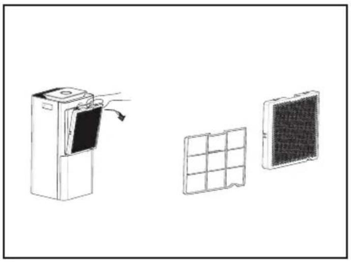
Two identical hand-drawn diagrams of a device being open, showing the left and right views with arrows indicating motion (no text or symbols)Fig. 4
natural_image
Diagram showing three components: a refrigerator with a scroll, a grid-patterned panel, and a rectangular panel (no text or symbols)ATENCIÓN
ATENCIÓN
AVISO
PLEASE USE THE INSTRUCTIONS FOR USE CAREFULLY PRIOR TO USING THE PRODUCT. STORE THESE IN A SAFE PLACE FOR FUTURE REFERENCE
SAFETY INSTRUCTIONS
This appliance can be used by children aged from 8 years and above and persons with reduced physical, sensory or mental capabilities or lack of experience and knowledge if they have been given supervision or instruction concerning use of the appliance in a safe way and understand the hazards involved.
Children shall not play with the appliance.
Cleaning and user maintenance shall not be made by children without supervision.
If the supply cord is damaged it must be replaced by the manufacturer, its service agent or similarly qualified persons in order to avoid a hazard.
Appliance shall be installed with national wiring regulations. Minimum permissible distance for top and back part of the appliance to adjacent structures is 30cm. For front, left and right part of the appliance is 20cm.
Appliance uses T or F type fuse rated at 250V voltage and 3,15 current.
WARNING
- Do not use means to accelerate the defrosting process or to clean, other than those recommended by the manufacturer.
- The appliance shall be stored in a room without continuously operating ignition sources (for example: open flames, an operating gas appliance or an operating electric heater).
- Do not pierce or burn.
- Be aware that refrigerants may not contain an odor.
- Appliance shall be installed, operated and stored in a room with a floor area larger than 4m2.
Maximum refrigerant R290 charge amount: 60g.
Dispose of refrigerant based on local regulations, properly process.
Servicing shall be performed only as recommended by the manufacturer.
WARNING: Keep ventilation openings clear of obstruction.
WARNING: Appliance shall be stored in a well-ventilated area where the room size corresponds to the room area as specified for operation.
WARNING: Appliance shall be stored in a room without continuously operating open flames (for example an operating gas appliance) and ignition sources (for example an operating electric heater).
The appliance shall be stored so as to prevent mechanical damage from occurring.
Any person who is involved with working on or breaking into a refrigerant circuit should hold a current valid certificate from an industry-accredited assessment authority, which authorizes their competence to handle refrigerants safely in accordance with an industry, recognized assessment
specification.
Servicing shall only be performed as recommended by the equipment manufacturer. Maintenance and repair requiring the assistance of other skilled personnel shall be carried out under the supervision of the person competent in the use of flammable refrigerants.
IMPORTANT WARNINGS
This appliance is designed for home use and should never be used for commercial or industrial use under any circumstances. Any incorrect use or improper handling of the product shall render the warranty null and void.
Prior to plugging in the product, check that your mains voltage is the same as the one indicated on the product label.
The mains connection cable must not be tangled or wrapped around the product during use.
Do not use the device, or connect and disconnect to the supply mains with the hands and / or feet wet.
Do not pull on the connection cord in order to unplug it or use it as a handle.
Never attempt to turn off the dehumidifier by disconnecting the plug.
To avoid risk of fire or explosion, do not spray to the dehumidifier. Do not put any inflammables or chemicals near the unit.
To prevent plastic parts from melting or catching on fire, do not place the dehumidifier near heating appliances.
Remove water that has been collected in the tank (accidentally drinking of the water or using it for other purpose may cause illness and /or unforeseen accidents).
Moving and hot parts: Do not operate unit with back cover removed.
The dehumidifier must be used on a level and stable surface.
Do not use the humidifier and the drain hose at ambient below O^ to prevent the water from freezing.
Do not use outdoors.
Be careful that a heating appliance is not exposed to the wind from the humidifier.
Do not cover the unit with washed clothes or similar.
Unplug the product immediately from the mains in the event of any breakdown or damage and contact an official technical support service. In order to prevent any risk of danger, do not open the device. Only qualified technical personnel from the brand's Official technical support service may carry out repairs or procedures on the device.
B&B TRENDS SL. disclaims all liability for damages that may occur to people, animals or objects, for the non-observance of these warnings.
DESCRIPTION
Front
- Power switch
- Air Outlet
- Handle
Back
- Air Inlet
- Water tank
- Castors
- Draining hose
Panel control
- High wind
- Low wind
- Timer
- Defrost
- Water tank full
- Switch
- Mode switch
- Fan
- Sleep mode
- Dehumidification
- Dry clothes
-
Humidity lamp
-
Continuous dehumidification
-
Humidity digital slide setting
INSTALLATION
For efficient operation of the dehumidifier, spacing is required as shown as picture 1.
Functions
The appliance has a tricolor lamp that shows the humidity level in the room.
- Blue light: If the indoor humidity is less than 50%, low humidity.
- Green light: If the indoor is between 50 and 70%, medium humidity.
- Red light: Indoor humidity higher than 70%, high humidity.
To prevent the light bar from bouncing back and for that the critical point, there is a 3% error setting.
Timer: Can be set from within 0-24hours.
Humidity setting: Set humidity with a range between 30 and 80%.
Fan speed: Set low or high speed.
Sleep mode: The appliance will run with minimum wind speed.
Mode selection: The pressing order is dehumidify→Continuous dehumidification→Dry Clothing function→Fan function.
Switch: Start the appliance, power failure memory.
Built-in microcomputer memorizes the operation of dehumidifier, once it is set.
The unit repeats the same operation by pressing on/off button switch (in case of disconnection by unplugging or power failure, start over the setting again).
HOW TO OPERATE
Make sure that the water tank is set properly.
Note: If the water tank is full, the water indicator light will be on and the rest are not displayed.
Plug the appliance to the mains.
Press the on/off switch. "Dehumidification" mode lamp will light up.
Set the unit to the desired operation by pressing "mode" switch (14).
Every time you press the “mode” switch, the mode select lamps light up in turn as dehumidifying→continuous drainage→Dry clothes→Fan.
TIMER
The dehumidifier will stop automatically after the hours set by the timer (0h to 24h).
In any mode, you can press "TIMER" switch to set the timer 0h to 24h.
When the timer button is pressed, the machine starts to enter the timer function and the icon will appear on the screen.
When the machine is turned on, the timing function can be used to delay off the machine.
When the unit is turned off, the timing function can be used to delay start the machine.
With the lapse of time, the timer lamp lighting up will indicate the remaining time.
The unit will stop operating after the lapse of the set time.
STOP OPERATING
To stop the appliance, press again the on/off switch.
The select mode lamp will goes off and the unit will stop operating.
NOTE:
Except “Continuous” mode operation, the timer set will be cancelled whenever “mode” switch pressed.
Set the timer again after pressing "mode" switch, if necessary.
The timer will stops when the water tank is full of water.
After the tank is emptied, the timer will start again.
DRY CLOTHES FUNCTIONS
Press the mode button until having the dry clothes lamp turns on.
WATER TANK FULL
If the water tank is full, the screen will appear to indicator light. At this time, the unit has stop running.
Put the water tank back in the unit and the dehumidifier will start working automatically.
Caution:
Do not remove the float from the water tank; otherwise, the machine will not stop to work when the water tank is full. Then the water will be overflow that maybe makes damage to your floor.
SET AIR FILTER
Open the rear cover.
Remove the filter holder from the front cover (fig.3)
Set the air cleaning filter on the rear cover.
Cover the filter in the four clips in the lid.
The air cleaning filter is upwards and the air cleaning filter is placed on the four hooks in the lid (the raised part of the cage is upwards).
When the conditions are not set correctly, the rear cover can not
To set the air cleaning filter firmly, press the circumference of your finger with your fingers. Then check the conditions.
In case of improper setting conditions you cannot set the back cover to the unit.
CONTINUOUS DRAINAGE
Pull the plug, take out the water tank and insert the drain pipe and put the other side into a container such as a bucket or a sewer (fig.2).
DEFROSTING OPERATION:
Both the dehumidifying function and the air cleaning function stop during the defrosting operation.
Do not disconnect the plug from the mains or turn off the unit during the defrosting process.
After 30 minutes of continuous operating for compressor, and if the temperature sensor detects that the copper tube is lower than 0^ C for one minute the compressor would stop operating for defrosting for ten minutes while the fan keeps operating.
After defrosting for ten minutes, or when the temperature sensor detects that the copper tube is higher than 10^ C for 30 seconds, the defrosting will be finished and the compressor will restart operating after three minutes for delay protection.
WARNING:
- Never block the water outlet or the pipe; water will flow into the water tank if it is blocked.
- Never bend the drainage pipe and be always lower than the outlet.
- Must close the cover when no need continuous drainage.
AFTER HAVING USING THE APPLIANCE:
Stop the appliance by pressing the on/off switch.
Unplug the unit from the mains.
Empty the water out of water tank, wipe the tank with cloth and replace in position.
Clean the appliance.
For storing, stand the unit upright and avoid the exposure to the direct sunlight.
CLEANING
Turn off the unit and disconnect the power plug before starting any cleaning task.
Cleaning the body:
Wipe the dehumidifier with a dry and soft cloth.
To remove heavy dirt, wipe it with a cloth wrung tightly.
Never use a wet cloth for cleaning the control panel.
DO NOT IMMERSE IN WATER OR ANY OTHER LIQUID.
To avoid any deformation or cracking, do not use benzene, thinner or liquid cleaners.
Chemical cloth may cause the change in the colour of the unit.
Air Filter
It is recommend you to clean the filter every 2 weeks.
When the air cleaning filter is blocked, the dehumidification capacity will be reduced. Remove the rear cover from the unit. Then remove the air cleaning filter (fig.4)
Pull the sider cover toward you and remove it from the unit. Remove the sider filter from the unit.
To dislodge the dust from these filters, use a vacuum clear or pat them lightly.
Pat the air clean filter and dislodge dust from it.
TROUBLE-SHOOTING
Take the appliance to an authorised technical support service if product is damaged or other problems arise. Do not attempt to disassemble or repair the appliance yourself as this may be dangerous.
| PROBLEM POINTS | TO BE CHECKED MEASURES TO BE TAKEN | |
| No operation | Check if the power plug is disconnected.Check to see if the water tank is full of water.Check if the water tank is not set properly in position.Check if all the flaps are closed. | Insert the plug into an electric outlet fully and securely.Empty the water out of the tank.Set the tank to the unit properly position.Open one of the flaps |
| Dehumidified volume is dirty | Is the filter dirty?Are the air opening blocked?Is the dehumidifier in ventilation mode? | Clean the filter as instructions.Remove obstacles from the air openings.Change the operation mode to the dehumidifying mode |
| O funcionamento é ruidoso | Is the unit installed as specified? | Install the unit on a level and stable floor. |
| Operation stops during dehumidifying | Check to see if the room temperature is higher than the usable operating temperature | The dehumidifying operation will be started automatically when the temperature lowers. |
| Washed clothes are not dried | Check to see if washed clothes are not exposed to the air from the unit.Check to see if the room temperature is too low. | Try to exposed the washed clothes to the air flow.Washed clothes are hard to be dried under low temperature conditions. |
PRODUCT DISPOSAL
This product complies with European Directive 2012/19/EU on electrical and electronic devices, known as WEEE (Waste Electrical and Electronic Equipment), provides the legal framework applicable in the European Union for the disposal and reuse of waste electronic and electrical devices. Do not dispose of this product in the bin, instead going to the electrical and electronic waste collection centre closest to your home.
INFORMATION ON SERVICING
Check to the area
Prior to beginning work on systems containing flammable refrigerants, safety checks are necessary to ensure that the risk of ignition is minimised. For repair to the refrigerating system, the following precautions shall be complied with prior to conducting work on the system.
Work procedure
Work shall be undertaken under a controlled procedure as to minimise the risk of a flammable gas or vapour being present while the work is being performed.
General work area
All maintenance staff and others working in the local area shall be instructed on the nature of work being carried out. Work in confined spaces shall be avoided. The area around the workspace shall be sectioned off. Ensure that the conditions within the area have been made safe by control of flammable material.
Checking for presence of refrigerant
The area shall be checked with an appropriate refrigerant detector prior to and during work, to ensure the technician is aware of potentially flammable atmospheres. Ensure that the leak detection equipment being used is suitable for use with flammable refrigerants, i.e. non-sparking, adequately sealed or intrinsically safe.
Presence of fire extinguisher
If any hot work is to be conducted on the refrigeration equipment or any associated parts, appropriate fire extinguishing equipment shall be available to hand. Have a dry powder or CO2 fire extinguisher adjacent to the charging area.
No ignition sources
No person carrying out work in relation to a refrigeration system which involves exposing any pipe work that contains or has contained flammable refrigerant shall use any sources of ignition in such a manner that it may lead to the risk of fire or explosion. All possible ignition sources, including cigarette smoking, should be kept sufficiently far away from the site of installation, repairing, removing and disposal, during which flammable refrigerant can possibly be released to the surrounding space. Prior to work taking place, the area around the equipment is to be surveyed to make sure that there are no flammable hazards or ignition risks. "No Smoking" signs shall be displayed.
Ventilated area
Ensure that the area is in the open or that it is adequately ventilated before breaking into the system or conducting any hot work. A degree of ventilation shall continue during the period that the work is carried out. The ventilation should safely disperse any released refrigerant and preferably expel it externally into the atmosphere.
Checks to the refrigeration equipment
Where electrical components are being changed, they shall be fit for the purpose and to the correct specification. At all times the manufacturer's maintenance and service guidelines shall be followed. If in doubt consult the manufacturer's technical department for assistance.
The following checks shall be applied to installations using flammable refrigerants:
- the charge size is in accordance with the room size within which the refrigerant containing parts are installed;
- the ventilation machinery and outlets are operating adequately and are not obstructed;
- if an indirect refrigerating circuit is being used, the secondary circuit shall be checked for the presence of refrigerant;
- marking to the equipment continues to be visible and legible. Markings and signs that are illegible shall be corrected;
- refrigeration pipe or components are installed in a position Where they are unlikely to be exposed to any substance which may corrode refrigerant containing components, unless the components are constructed of materials which are inherently resistant to being corroded or are suitably protected against being so corroded.
Checks to electrical devices
Repair and maintenance to electrical components shall include initial safety checks and component inspection procedures. If a fault exists that could compromise safety, then no electrical supply shall be connected to the circuit until it is satisfactorily dealt with. If the fault cannot be corrected immediately but it is necessary to continue operation, an adequate temporary solution shall be used. This shall be reported to the owner of the equipment so all parties are advised.
Initial safety checks shall include:
- that capacitors are discharged: this shall be done in a safe manner to avoid possibility of sparking;
- that no live electrical components and wiring are exposed while charging, recovering or purging the system;
• that there is continuity of earth bonding.
Repairs to sealed components
During repairs to sealed components, all electrical supplies shall be disconnected from the equipment being worked upon prior to any removal of sealed covers, etc. If it is absolutely necessary to have an electrical supply to equipment during servicing, then a permanently operating form of leak detection shall be located at the most critical point to warn of a potentially hazardous situation.
Particular attention shall be paid to the following to ensure that by working on electrical components, the casing is not altered in such a way that the level of protection is affected. This shall include damage to cables, excessive number of connections, terminals not made to original specification, damage to seals,
incorrect fitting of glands, etc.
Ensure that apparatus is mounted securely.
Ensure that seals or sealing materials have not degraded such that they no longer serve the purpose of preventing the ingress of flammable atmospheres. Replacement parts shall be in accordance with the manufacturer's specifications.
NOTE The use of silicon sealant may inhibit the effectiveness of some types of leak detection equipment. Intrinsically safe components do not have to be isolated prior to working on them.
Repair to intrinsically safe components
Do not apply any permanent inductive or capacitance loads to the circuit without ensuring that this will not exceed the permissible voltage and current permitted for the equipment in use.
Intrinsically safe components are the only types that can be worked on while live in the presence of a flammable atmosphere. The test apparatus shall be at the correct rating.
Replace components only with parts specified by the manufacturer. Other parts may result in the ignition of refrigerant in the atmosphere from a leak.
Cabling
Check that cabling will not be subject to wear, corrosion, excessive pressure, vibration, sharp edges or any other adverse environmental effects. The check shall also take into account the effects of ageing or continual vibration from sources such as compressors or fans.
Detection of flammable refrigerants
Under no circumstances shall potential sources of ignition be used in the searching for or detection of refrigerant leaks. A halide torch (or any other detector using a naked flame) shall not be used.
Leak detection methods
The following leak detection methods are deemed acceptable for systems containing flammable refrigerants.
Electronic leak detectors shall be used to detect flammable refrigerants, but the sensitivity may not be adequate, or may need re-calibration. (Detection equipment shall be calibrated in a refrigerant-free area.) Ensure that the detector is not a potential source of ignition and is suitable for the refrigerant used. Leak detection equipment shall be set at a percentage of the lower flammability limit (LFL) of the refrigerant and shall be calibrated to the refrigerant employed and the appropriate percentage of gas (25 % maximum) is confirmed.
Leak detection fluids are suitable for use with most refrigerants but the use of detergents containing chlorine shall be avoided as the chlorine may react with the refrigerant and corrode the copper pipe-work.
If a leak is suspected, all naked flames shall be removed/ extinguished.
If a leakage of refrigerant is found which requires brazing, all of the refrigerant shall be recovered from the system, or isolated (by means of shut off valves) in a part of the system remote from the leak. Oxygen free nitrogen (OFN) shall then be purged through the system both before and during the brazing process.
Removal and evacuation
When breaking into the refrigerant circuit to make repairs-or for any other purpose-conventional procedures shall be used. However, it is important that best practice is followed since flammability is a consideration. The following procedure shall be adhered to:
- remove refrigerant ;
• purge the circuit with inert gas; - evacuate;
• purge again with inert gas; - open the circuit by cutting or brazing.
The refrigerant charge shall be recovered into the correct recovery cylinders. The system shall be "flushed" with octafluoronaphthalene (OFN) to render the unit safe. This process may need to be repeated several times. Compressed air or oxygen shall not be used for this task.
Flushing shall be achieved by breaking the vacuum in the system with OFN and continuing to fill until the working pressure is achieved, then venting to atmosphere, and finally pulling down to a vacuum.
This process shall be repeated until no refrigerant is within the system. When the final OFN charge is used, the system shall be vented down to atmospheric pressure to enable work to take place. This operation is absolutely vital if brazing operations on the pipe-work are to take place.
Ensure that the outlet for the vacuum pump is not close to any ignition sources and there is ventilation available.
Charging procedures
In addition to conventional charging procedures, the following requirements shall be followed.
- Ensure that contamination of different refrigerants does not occur when using charging equipment. Hoses or lines shall be as short as possible to minimise the amount of refrigerant contained in them.
- Cylinders shall be kept upright.
- Ensure that the refrigeration system is earthed prior to charging the system with refrigerant.
- Label the system when charging is complete (if not already).
- Extreme care shall be taken not to overfill the refrigeration system.
Prior to recharging the system, it shall be pressure tested with OFN. The system shall be leak tested on completion of charging but prior to commissioning. A follow up leak test shall be carried out prior to leaving the site.
Decommissioning
Before carrying out this procedure, it is essential that the technician is completely familiar with the equipment and all its detail. It is recommended good practice that all refrigerants are recovered safely.
Prior to the task being carried out, an oil and refrigerant sample shall be taken in case analysis is required prior to re-use of reclaimed refrigerant. It is essential that electrical power is available before the task is commenced.
a) Become familiar with the equipment and its operation.
b) Isolate system electrically.
c) Before attempting the procedure ensure that:
- mechanical handling equipment is available, if required, for handling refrigerant cylinders;
- all personal protective equipment is available and being used correctly;
- the recovery process is supervised at all times by a competent person;
- recovery equipment and cylinders conform to the appropriate standards.
d) Pump down refrigerant system, if possible.
e) If a vacuum is not possible, make a manifold so that refrigerant can be removed from various parts of the system.
f) Make sure that cylinder is situated on the scales before recovery takes place.
g) Start the recovery machine and operate in accordance with manufacturer's instructions.
h) Do not overfill cylinders. (No more than 80 % volume liquid charge).
i) Do not exceed the maximum working pressure of the cylinder, even temporarily.
j) When the cylinders have been filled correctly and the process completed, make sure that the cylinders and the equipment are removed from site promptly and all isolation valves on the equipment are closed off.
k) Recovered refrigerant shall not be charged into another refrigeration system unless it has been cleaned and checked.
Labelling
Equipment shall be labelled stating that it has been de-commissioned and emptied of refrigerant. The label shall be dated and signed. Ensure that there are labels on the equipment stating the equipment contains flammable refrigerant.
Recovery
When removing refrigerant from a system, either for servicing or decommissioning, it is recommended good practice that all refrigerants are removed safely.
When transferring refrigerant into cylinders, ensure that only appropriate refrigerant recovery cylinders are employed. Ensure that the correct number of cylinders for holding the total system charge is available. All cylinders to be used are designated for the recovered refrigerant and labelled for that refrigerant (i.e. special cylinders for the recovery of refrigerant). Cylinders shall be complete with pressure relief
valve and associated shut-off valves in good working order. Empty recovery cylinders are evacuated and, if possible, cooled before recovery occurs.
The recovery equipment shall be in good working order with a set of instructions concerning the equipment that is at hand and shall be suitable for the recovery of flammable refrigerants. In addition, a set of calibrated weighing scales shall be available and in good working order. Hoses shall be complete with leak-free disconnect couplings and in good condition. Before using the recovery machine, check that it is in satisfactory working order, has been properly maintained and that any associated electrical components are sealed to prevent ignition in the event of a refrigerant release. Consult manufacturer if in doubt. The recovered refrigerant shall be returned to the refrigerant supplier in the correct recovery cylinder, and the relevant Waste Transfer Note arranged. Do not mix refrigerants in recovery units and especially not in cylinders.
If compressors or compressor oils are to be removed, ensure that they have been evacuated to an acceptable level to make certain that flammable refrigerant does not remain within the lubricant. The evacuation process shall be carried out prior to returning the compressor to the suppliers. Only electric heating to the compressor body shall be employed to accelerate this process. When oil is drained from a system, it shall be carried out safely.
FRANÇAIS
NOUS TENONS À VOUS REMERCIER D'AVOIR CHOISI UFESA. NOUS ESPÉRONS QUE VOUS SEREZ PLEINEMENT SATISFAIT DE CE PRODUIT ET QU'IL RÉPONDRA À VOS ATTENTES.
ATTENTION
VEUILLEZ LIRE ATTENTIVEMENT LE MANUEL D'UTILISATION AVANT D'UTILISER LE PRODUIT. CONSERVEZ CE MANUEL D'UTILISATION DANS UN ENDROIT SÛR EN VUE DE CONSULTATION FUTURE.
CONSIGNES DE SÉCURITÉ
ATTENTION
ÉLIMINATION DU PRODUIT
ВНИМАНИЕ
Caution, risk of fire
تحذیر
B&B TRENDS, SL. guarantees compliance of this product for the use for which it is intended for a period of two years. In the case of breakdown during the term of this warranty, users are entitled to repair or else the replacement of the product at no charge if the former is unavailable, unless one of these options proves impossible to fulfill or is disproportionate. In this case, you can then opt for a reduction in price or cancellation of the sale, which must be dealt with directly with the sales vendor. This also covers replacement of spare parts provided that the product has been used according to the recommendations specified in this manual for both cases, and has not been tampered with by any third party that is not authorised by B&B TRENDS, SL. The warranty will not cover any parts subject to wear and tear. This warranty does not affect your rights as a consumer in accordance with the provisions in Directive 1999/44/EC for member states of the European Union.
USE OF WARRANTY
Customers must contact a B&B TRENDS, SL., authorised Technical Service for repair of the product. Since any tampering of the same by anyone not authorised by B&B TRENDS, SL., or the careless or improper use of the same shall render this warranty null and void. The warranty must be fully completed and delivered along with the receipt or delivery docket for the effective exercise of rights under this warranty.
This warranty should be retained by the user as well as the invoice, receipt or the delivery docket to facilitate the exercise of these rights. For technical service and after-sales care outside the Spanish territory, please submit your query to the point of sale where you purchased the item.
BOLETIM DE GARANTIA
SUM. ELECT. DALMAU, S.C.P.
VILADOMAT, 108
934539276
sdalmau@ono.com
08240 MANRESA
SERVICIO ELDE - JORGE MANERO
BRUCH, 55
938728542
elde@eldeservei.com
08027 BARCELONA
SELAROM
PASSEIG MARAGALL, 102
933 521 805
amoralesnieto@hotmail.com
08020 BARCELONA
SAT MARINE, S.C.P.
C/HUELVA, 67-69
932664697
satmarine@satmarinescp.com
08620 SANT VICENÇ DELS HORTS
SAT JARO -
C/ MALAGA, 20-22
647 054 779
jroca78@gmail.com
08950 ESPLUGUES DE LLOBREGAT
SAT J. BAUTISTA
POL.INDR."DOMENYS I" NAVE 9
938904852
fred@fredvilafranca.com
SUREDA I ASSOCIATS, S.C.
FRANCESC ARTAU, 2
972236588
resuredgirona@gmail.com
17200 PALAFRUGELL
NEW MERESA
DE LA SURERA BERTRAN, 23
972304454
comercial@newmeresa.com
17300 BLANES
FRANCISCO PORTILLO PEIRO
ASIAS MARC 1
972331249
serviciotecnico@portillotv.com
17740 VILAFANT
ELECTRONICA VILAFANT - SAT
NAVATA, 13
972506515/615090154
electronicavilafant@hotmail.com
GRANADA
18015 GRANADA
LUNSOL, S.L.
AVDA. VIRGEN DE LA CONSO 4,
LOCAL 2
958292565
info@lunsol.net
18007 GRANADA
ELECTRICIDAD MORENO
C/ PALENCIA, 3
95 881 05 35
morenotorres@carretero200.com
GUADALAJARA
19004 GUADALAJARA
FERRETERIA AL-YE
AVDA, EJERCITO,11-D POSTERIOR
949218662
ferreteriaal_ye1@hotmail.com
GUIPUZCOA
20014 SAN SEBASTIAN (no oficial)
SANTIAGO ESTALAYO
SANTIAGO APOSTOL 18 Local
959283415/627349431
URBISAT (BALEAR SERVICE)
C/MATEU OBRADOR,8
971-733886/733879
alanurbisat@gmail.com
7740 MENORCA
ES MERCADAL
SERVEIS MENORCA, S.L.
CARRER NOU N° 53
971375380
serveismenorca@gmail.com
JAÉN
23400 UBEDA
MAGOCA UBEDA
GRANADA 7
953751838
ubedasatmagoca@gmail.com
23001 JAEN
CARRIL DE LAS FLORES, 34-B
982242015
teleservicio@telefonica.net
27400 MONFORTE DE LEMOS
RAUL E HIJOS,S.L
CAMPO DE LA COMPAÑÍA, 19
982400711
raulehijos@gmail.com
27850 VIVERO (CASCO
SERVICIO TECNICO SILDO 101, S.L.U.
LODEIRO, 26
982061819
MADRID
28931 MOSTOLES
Valle Inclan 32 Local
917054624
pimaruno@gmail.com
28047 CARABANCHEL
REPARACIONES CARLOS (CARLOS
GOMEZ YUSTE)
GUABAIRO,2
914665369
Electro Servicio Muñoz S. L. (ESM
Corella)
C/ Santa Barbara, 52
948780729
satcorella@gmail.com
31500 TUDELA
ELECTRICIDAD FERNANDO, S.C.I.
YANGUAS Y MIRANDA, 12
948826457
electrohogar@electrohogartoledo.com
VALENCIA
46600 ALZIRA
TALLERES MOYA
C/ FAVARETA,49
96 241 85 87
tamoya@talleresmoya.com
46011 VALENCIA
ROBERTO BARRACHINA ALIAGA
-VALENCIANA, SA TECNICA-
C/FRANCISCO BALDOMA, 86 Bajos
963554244/607304279
valencianasat@gmail.com
46700 GANDIA
RELGAN - CAMILO GARCIA
MAGISTRADO CATALA, 16
962872810
relgangandia@gmail.com
46005 VALENCIA
RELEVAN,S.L.
C/ MATIAS PERELLO,49
963 222 529
merce@relevansl.com
46800 XATIVA
JOSE PASTOR DIEZ
C/ ABU MASAIFA, 6
962274794
sat-xativa@josepastor.es
46680 ALGEMESI
JOSE A. LLACER SANGROS
ALBALAT, 88
962423519
satllacer@hotmail.com
46700 GANDIA
JOAQUIN MAYOR ESTRUGO
(TECNOGAR)
PRIMER DE MAIG 41-B
962865335
tecnogar33@gmail.com