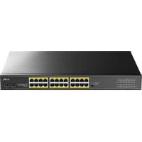
GS1028PS2 - Switch Cudy - Free user manual and instructions
Find the device manual for free GS1028PS2 Cudy in PDF.


| Product Type | Gigabit Unmanaged PoE Switch |
| Model | Cudy GS1028PS2 |
| Network Standards | IEEE 802.3, 802.3u, 802.3ab, 802.3z, 802.3x, 802.3af, 802.3at |
| Ports | 24 PoE ports RJ45 10/100/1000 Mbps, 2 Gigabit combo ports (RJ45/SFP), 2 RJ45 ports 10/100/1000 Mbps |
| PoE Power Supply | Ports 1 to 24, Mode A (1/2(-),3/6(+)), max power 32 W per port |
| PoE Budget | 250 W / 370 W / 300 W (depending on version, optional fanless) |
| Switching Capacity | 56 Gbps |
| MAC Address Table | 8K entries, auto-learning and auto-aging |
| Transfer Mode | Store-and-Forward |
| Dimensions (W×D×H) | 440 × 207 × 44 mm |
| Power Supply | AC 100-240 V, 50/60 Hz |
| Max Power Consumption | 370 W (depending on PoE budget) |
| Cooling | 2 fans or fanless version (optional) |
| Operating Temperature | 0 °C to 40 °C |
| Storage Temperature | -40 °C to 70 °C |
| Operating Humidity | 10% to 90% (non-condensing) |
| Storage Humidity | 5% to 90% (non-condensing) |
| DIP Switch Modes | Default (factory mode), VLAN (isolation of ports 1-24 with uplink to ports 25-28), CCTV (PoE extension up to 250 m) |
| Installation | Desktop (with rubber feet) or 19-inch rack (mounting brackets included) |
| Maintenance and Cleaning | Unplug before cleaning; use a dry cloth; do not use liquid or damp cloth |
| Safety | Do not open the case while powered on; avoid water and moisture; ensure adequate ventilation |
| Package Contents | PoE Switch, User Guide, Power Cord |
Frequently Asked Questions - GS1028PS2 Cudy
User questions about GS1028PS2 Cudy
0 question about this device. Answer the ones you know or ask your own.
Ask a new question about this device
Download the instructions for your Switch in PDF format for free! Find your manual GS1028PS2 - Cudy and take your electronic device back in hand. On this page are published all the documents necessary for the use of your device. GS1028PS2 by Cudy.
USER MANUAL GS1028PS2 Cudy
● Accessories(hanging ears*2,Rubber Feet*4,screw*8)
LED-Anzeige
Check the following contents of your package:
- PoE Switch x 1
- User Guide x 1
● Power Cord x 1
● Accessories(hanging ears*2,Rubber Feet*4,screw*8)
If any part is lost and damaged, please contact your local agent immediately.
Introduction
The 24GE(PoE)+2G Combo+2GE PoE Switch are Gigabit Uplink Unmanaged Switch which provides you with a high-performance, low-cost, easy-to-use, seamless and standard upgrade to boost your old network to 10/100/1000Mbps. Increase the speed of your network server and backbone connections, making Gigabit connection to a server or uplinking a network necessarily.
Its PoE ports can automatically detect and supply power with those IEEE 802.3af/at compliant Powered Devices (PD). The electrical power is transmitted along with data in one single cable allowing you to expand your network where there are no power lines or outlets, where you wish to fix devices such as AP, IP Cameras or IP Phones, etc.
Hardware Description
Front Panel
The Front Panel Consists of 24-Port 10/100/1000M Auto-Negotiation RJ45 PoE Ports, 2-Port Gigabit Combo Port and 2-Port 10/100/1000M RJ45 port. The LED indicators also on located on the panel.

LED indicator
| LED Color Function | ||
| PWR Green | Off: No Power supplyLight: Indicates the switch has power | |
| LNK/ACT | Green | Off: No device is connected to the corresponding portLight: Indicates the link through that port is successfully established at 1000Mbps.Blink: Indicates that the Switch is actively sending or receiving data over that port. |
| Orange | Off: No device is connected to the corresponding portLight: Indicates the link through that port is successfully established at 10/100Mbps.Blink: Indicates that the Switch is actively sending or receiving data over that port. | |
| PoE Orange | Off: No PoE powered device (PD) connectedLight: There is a PoE PD connected to be port, which supply power successfully.Blink: Indicates port abnormal power supply | |
DIP Switch
The DIP switch located on the left panel.
Default: the factory default mode, can normal communication between port 1\~28.
VLAN: 1-24 port can be isolated each other but 1-24 port can connect to 25 \~28 port after open VLAN to stop broadcast storm to increase forwarding rate of frame.
CCTV: Up to 250m PoE distance allows you to expand you network via Ethernet cable but where you want to fix device such as IP Cameras.
Note: After change the mode, in order to the corresponding configuration take effect. The switch needs to restart manually.
Rear Panel
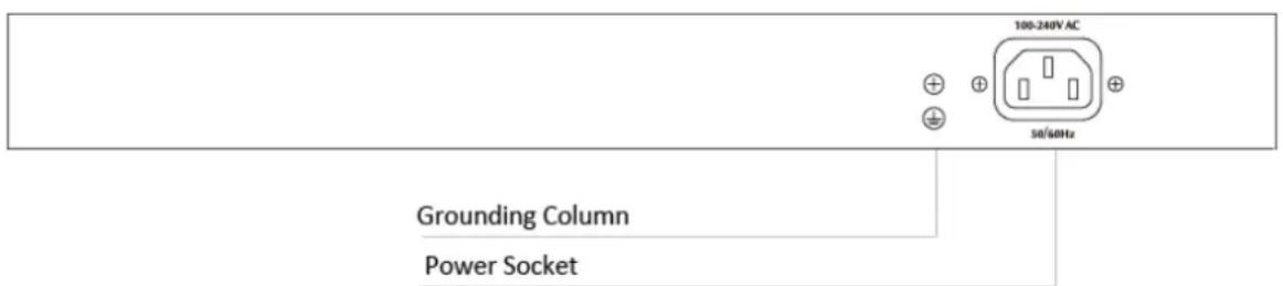
The rear panel of 24GE(PoE)+2G Combo+2GE PoE Switch indicates an AC inlet power socket, Grounding Column.
Installation the Switch
This part describes how to install your Ethernet Switch and make connections to it. Please follow the following instructions in avoid of incorrect installation causing device damage and security threat.
● Before cleaning the switch, unplug the power plug of the switch first. Do not clean the switch with wet cloth or liquid;
- Do not place the switch near water or any damp area. Prevent water or moisture from entering the switch chassis;
● Do not place the switch on an unstable case or desk. The switch might be damaged severely in case of a fall;
● Ensure proper ventilation of the equipment room and keep the ventilation vents of the switch free of obstruction:
● Make sure that the operating voltage is the same one labeled on the switch;
● Do not open the chassis while the switch is operating or when electrical hazards are present to avoid electrical shocks.
Desktop Installation
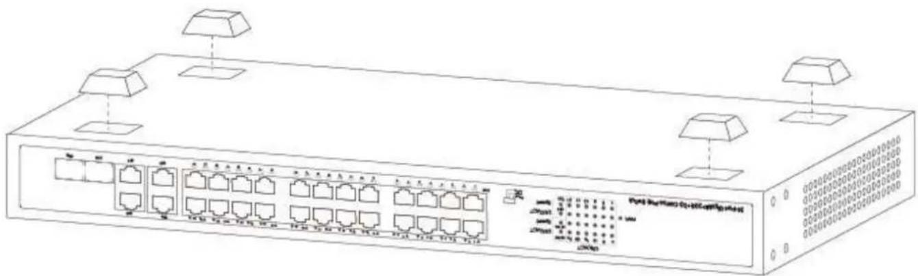
Install the Switch on a desktop, please attach these cushioning rubber feet provided on the bottom at each corner of the Switch in case of the external vibration. Allow adequate space for ventilation between the device and the objects around it. The installation diagram is as follows:
Rack-mountable Installation
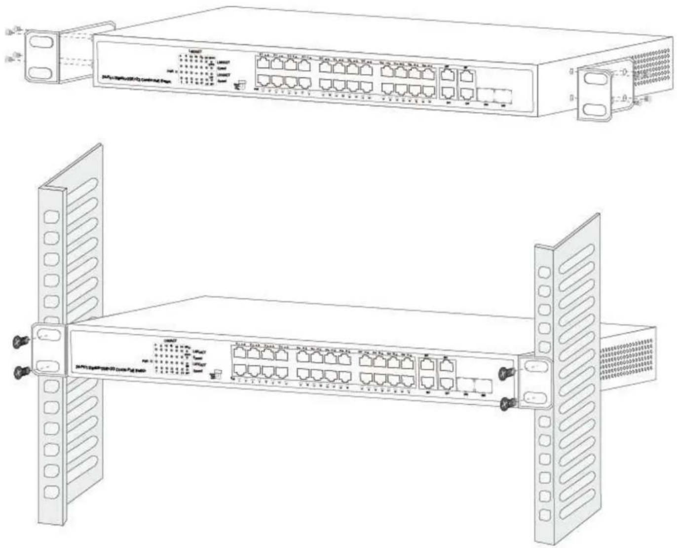
The switch is rack-mountable and can be installed on an EIA-19 inch equipment rack. To do this, first, please install the mounting brackets on the switch's side panels (one on each side), secure them with the included screws, and then use the screws provided with the equipment rack to mount the switch on the 19 inch rack.
Turn on the switch
Plug in the negative connector of the provided power cord into the power socket of the device, and the positive connector into a power outlet. After the device is powered on, it begins the Power-On Self-Test. The PWR LED indicator will light on all the time.
Specifications
| Model | 24GE(PoE)+2G Combo+2GE |
| Standard | IEEE802.3, IEEE802.3u, IEEE802.3ab, IEEE802.3z, IEEE802.3x, IEEE802.3af, IEEE802.3at |
| Network Media(Cable) | 10BASE-T: UTP category 3,4,5 cable (≤100m)100BASE-TX: UTP category 5 cable (≤100m)1000BASE-T: UTP category 5e cable (≤100m)1000BASE-X: MMF or SMF SFP module |
| MAC Address Table | 8K, Auto-learning, Auto-aging |
| Transfer mode Store-and-Forward | |
| Frame Forward Rate | 10Base-T: 14881pps/Port100Base-TX: 148810pps/Port1000Base-T/X: 1488095pps/Port |
| Switching Capacity 56Gbps | |
| Dimensions (L*W*H) | 440*207*44 mm |
| Fan 2/Fanless(Optional) | |
| Power Input AC: 100~240V, 50/60Hz | |
| PoE Port Port1~24 | |
| PoE Power on RJ45 | Mode A 1/2(-),3/6(+) |
| PoE Power Output 32W(Max) | |
| PoE Power budget | 250W/370W/300W Fanless(Optional) |
| Temperature | Operating Temperature: 0°C ~ 40 °C (32 °F ~104°F)Storage Temperature: -40 °C ~ 70 °C (-40 °F ~158°F) |
| Humidity | Operating Humidity: 10% ~ 90% non-condensingStorage Humidity: 5% ~ 90% non-condensing |
Guía del usuario
24GE(PoE)+2G Combo+2GE PoE Switch
● Accessories(hanging ears*2,Rubber Feet*4,screw*8)
Indicador LED
Instalación en rack
Encender el interruptor
● Accessories(hanging ears*2,Rubber Feet*4,screw*8)
Indicateur LED
● Accessories(hanging ears*2,Rubber Feet*4,screw*8)
Indicatore LED

Brand : Cudy
Model : GS1028PS2
Category : Switch