
PR501AC - Router Vonroc - Free user manual and instructions
Find the device manual for free PR501AC Vonroc in PDF.

| Product type | Router |
| Brand | Vonroc |
| Model | PR501AC |
| Rated voltage | 230 V~ |
| Frequency | 50 Hz |
| Power consumption | 1200 W |
| No-load speed | 16000 - 30000 min⁻¹ |
| Max. cutting depth | 55 mm |
| Cutter collet diameter | 6 mm and 8 mm |
| Weight | 3.6 kg |
| Sound pressure level (Lpa) | 92.1 dB(A) |
| Sound power level (Lwa) | 103.1 dB(A) |
| Vibration | 2.105 m/s² |
| Double insulation | Yes |
| Intended use | Grooving, profiling, copying in wood and derived materials |
| Maintenance | Clean dust, keep handles dry and clean |
| Safety | PPE mandatory, read all warnings |
| Spare parts | Use only original parts |
| Warranty | According to applicable legislation, contact VONROC |
Frequently Asked Questions - PR501AC Vonroc
User questions about PR501AC Vonroc
0 question about this device. Answer the ones you know or ask your own.
Ask a new question about this device
Download the instructions for your Router in PDF format for free! Find your manual PR501AC - Vonroc and take your electronic device back in hand. On this page are published all the documents necessary for the use of your device. PR501AC by Vonroc.
USER MANUAL PR501AC Vonroc
natural_image
Simple white icon of a mechanical device with no text or symbolsEN Original Instructions
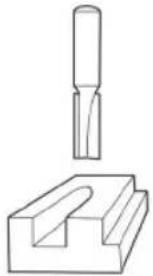
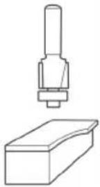
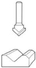
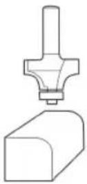
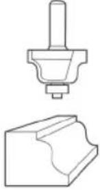
| Straight 12mm | Flush trim 12.7mm | 90°V Groove 12.7mm | Round over 6.35mm | 45° Chamfer 32mm | Roman ogee R4 |
 |  |  |  |  |  |
A
101112
UONROC
natural_image
Technical line drawing of a mechanical device with springs and a rope, no visible text or symbols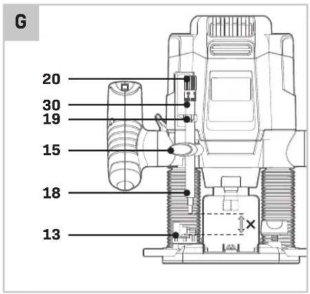
natural_image
3D mechanical component diagram with directional arrows and cross symbols (no readable text or labels)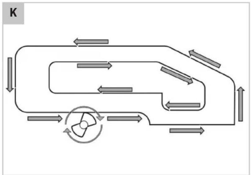
flowchart
graph TD
    A["Top Left Side"] --> B["Top Right Side"]
    B --> C["Bottom Left Side"]
    C --> D["Bottom Right Side"]
    D --> E["Bottom Center"]
    E --> F["Center Fan"]
    F --> G["Bottom Right Side"]
    G --> H["Bottom Left Side"]
    H --> I["Bottom Right Side"]
    I --> J["Bottom Center"]
    J --> K["Bottom Right Side"]
    K --> L["Bottom Left Side"]
    L --> M["Bottom Right Side"]
    M --> N["Bottom Center"]
    N --> O["Bottom Right Side"]
    O --> P["Bottom Left Side"]
    P --> Q["Bottom Right Side"]
    Q --> R["Bottom Center"]
    R --> S["Bottom Right Side"]
    S --> T["Bottom Left Side"]
    T --> U["Bottom Right Side"]
    U --> V["Bottom Center"]
    V --> W["Bottom Right Side"]
    W --> X["Bottom Left Side"]
    X --> Y["Bottom Right Side"]
    Y --> Z["Bottom Center"]
    Z --> AA["Bottom Right Side"]
    AA --> AB["Bottom Left Side"]
    AB --> AC["Bottom Right Side"]
    AC --> AD["Bottom Center"]
    AD --> AE["Bottom Right Side"]
    AE --> AF["Bottom Left Side"]
    AF --> AG["Bottom Right Side"]
    AG --> AH["Bottom Center"]
    AH --> AI["Bottom Right Side"]
    AI --> AJ["Bottom Left Side"]
1. SAFETY INSTRUCTIONS
Read the enclosed safety warnings, the additional safety warnings and the instructions. Failure to follow the safety warnings and the instructions may result in electric shock, fire and/or serious injury. Save the safety warnings and the instructions for future reference.
The following symbols are used in the user manual or on the product:

Read the instructions!

Risk of personal injury.

Risk of electric shock.

Wear ear protection.

Wear eye protection

Wear a dust mask.

Danger! Keep hands away from moving parts.

Your machine is double insulated, therefore no earthwire is required.

Conforms to all relevant European Directives.

Do not dispose of the product in unsuitable containers.
GENERAL POWER TOOL SAFETY WARNINGS

WARNING! Read all safety warnings and all instructions. Failure to follow the warnings and instructions may result in electric shock, fire and/or serious injury.
Save all warnings and instructions for future reference.
The term “power tool” in the warnings refers to your mains-operated (corded) power tool or battery-operated (cordless) power tool.
1) Work area safety
a) Keep the work area clean and well lit. Cluttered or dark areas invite accidents.
b) Do not operate power tools in explosive atmospheres, such as in the presence of flammable liquids, gases or dust. Power tools create sparks which may ignite the dust or fumes.
c) Keep children and bystanders away while operating a power tool. Distractions can cause you to lose control.
2) Electrical safety
a) Power tool plugs must match the outlet. Never modify the plug in any way. Do not use any adapter plugs with earthed (grounded) power tools. Unmodified plugs and matching outlets will reduce risk of electric shock.
b) Avoid body contact with earthed or grounded surfaces, such as pipes, radiators, ranges and refrigerators. There is an increased risk of electric shock if your body is earthed or grounded.
c) Do not expose power tools to rain or wet conditions. Water entering a power tool will increase the risk of electric shock.
d) Do not abuse the cord. Never use the cord for carrying, pulling or unplugging the power tool. Keep cord away from heat, oil, sharp edges or moving parts. Damaged or entangled cords increase the risk of electric shock.
e) When operating a power tool outdoors, use an extension cord suitable for outdoor use. Use of a cord suitable for outdoor use reduces the risk of electric shock.
f) If operating a power tool in a damp location is unavoidable, use a residual current device (RCD) protected supply. Use of an RCD reduces the risk of electric shock.
3) Personal safety
a) Stay alert, watch what you are doing and use common sense when operating a power tool. Do not use a power tool while you are tired or under the influence of drugs, alcohol or medication. A moment of inattention while operating power tools may result in serious personal injury.
b) Use personal protective equipment. Always wear eye protection. Protective equipment such as dust mask, non-skid safety shoes, hard hat, or hearing protection used for appropriate conditions will reduce personal injuries.
c) Prevent unintentional starting. Ensure the switch is in the off-position before connecting to power source and/or battery pack, picking up or carrying the tool. Carrying power tools with
your finger on the switch or energising power tools that have the switch on invites accidents.
d) Remove any adjusting key or wrench before turning the power tool on. A wrench or a key left attached to a rotating part of the power tool may result in personal injury.
e) Do not overreach. Keep proper footing and balance at all times. This enables better control of the power tool in unexpected situations.
f) Dress properly. Do not wear loose clothing or jewellery. Keep your hair, clothing and gloves away from moving parts. Loose clothes, jewellery or long hair can be caught in moving parts.
g) If devices are provided for the connection of dust extraction and collection facilities, ensure these are connected and properly used. Use of dust collection can reduce dust related hazards.
h) Do not let familiarity gained from frequent use of tools allow you to become complacent and ignore tool safety principles. A careless action can cause severe injury within a fraction of a second.
4) Power tool use and care
a) Do not force the power tool. Use the correct power tool for your application. The correct power tool will do the job better and safer at the rate for which it was designed.
b) Do not use the power tool if the switch does not turn it on and off. Any power tool that cannot be controlled with the switch is dangerous and must be repaired.
c) Disconnect the plug from the power source and/or the battery pack from the power tool before making any adjustments, changing accessories, or storing power tools. Such preventive safety measures reduce the risk of starting the power tool accidentally.
d) Store idle power tools out of the reach of children and do not allow persons unfamiliar with the power tool or these instructions to operate the power tool. Power tools are dangerous in the hands of untrained users.
e) Maintain power tools. Check for misalignment or binding of moving parts, breakage of parts and any other condition that may affect the power tool's operation. If damaged, have the power tool repaired before use. Many accidents are caused by poorly maintained power tools.
f) Keep cutting tools sharp and clean. Properly maintained cutting tools with sharp cutting edges
are less likely to bind and are easier to control.
g) Use the power tool, accessories and tool bits etc. in accordance with these instructions, taking into account the working conditions and the work to be performed. Use of the power tool for operations different from those intended could result in a hazardous situation.
h) Keep handles and grasping surfaces dry, clean and free from oil and grease. Slippery handles and grasping surfaces do not allow for safe handling and control of the tool in unexpected situations.
5) Service
a) Have your power tool serviced by a qualified repair person using only identical replacement parts. This will ensure that the safety of the power tool is maintained.
ADDITIONAL SAFETY INSTRUCTION FOR ROUTERS
- Hold the power tool by insulated gripping surfaces only, because the cutter may contact its own cord. Cutting a "live" wire may make exposed metal parts of the power tool "live" and could give the operator an electric shock.
- Use clamps or another practical way to secure and support the workpiece to a stable platform. Holding the work by your hand or against the body leaves it unstable and may lead to loss of control.
- Please check workpieces for any obstructions on the surface of the material, such as protruding nails etc., to protect the router head.
- Wait until the router has come to a complete stop before removing any blocked or routed material around the cutter. Use a long stick for this and never your finger.
- Please keep your hands away from the routing surface.
- Immediately switch off the tool if it starts producing any unusual noise or starts vibrating excessively.
- Please check that all parts are secure, tools are removed etc. before operation.
- Only bring the power tool into contact with the work-piece when switched on. Otherwise there is danger of kickback if the cutting tool jams in the workpiece.
-
Hold the power tool firmly with both hands and make sure you have a stable footing. The power tool can be more securely guided with both hands.
-
Only use router bits with a shank diameter equal to the size of the collet installed in the tool.
- The permitted speed of the cutting bit must be at least equal to the maximum speed marked on the powertool. If cutting bits run faster than their rated speed, they may break and fly off.
- Never use router bits with a diameter exceeding the maximum diameter specified in the technical data section. Routers and other accessories must be able to fit exactly in the tool holder (collet) of your power tool. Application tools that do not fit exactly in the tool holder of the power tool will turn unevenly, vibrate heavily and may cause a loss of control.
- Do not use the tool in an inverted position when holding it. Do not attempt to use the tool in a stationary mode, unless combined with specifically designed accessories as a router table.
- Take special care when routing MDF or surfaces coated with lead-based paint. Wear a dust mask specifically designed for protection against lead paint dust and fumes and ensure that persons within or entering the work area are also protected.
- Do not let children or pregnant women enter the work area.
- Do not eat, drink or smoke in the work area.
- Never rout over metal objects, nails or screws. The router could become damaged and cause increased vibration.
- Use suitable detectors to determine if utility lines are hidden in the work area or call the local utility company for assistance. Contact with electric lines can lead to fire and electric shock. Damaging a gas line can lead to explosion. Penetrating a water line causes property damage or may cause an electric shock.
- Dispose of dust particles and any other debris safely.
- Do not use blunt or damaged routers and router bits. Blunt or damaged routers and router bits cause increased friction, create imbalances and may become jammed.
- This appliance is not intended for use by young infirm persons without supervision. Children must be supervised to ensure they do not play with the appliance.
Electrical safety
Always check that the voltage of the power supply corresponds to the voltage on the rating plate.
- Do not use the machine if the mains cable or the mains plug is damaged.
- Only use extension cables that are suitable for the power rating of the machine with a minimum thickness of 1.5 mm ^2 . If you use an extension cable reel, always fully unroll the cable.
2. MACHINE INFORMATION
Intended use
This product is designed for copy routing as well as routing grooves, edges, profiles and elongated holes in wood and wood products while resting firmly on the workpiece. The router is intended for use in domestic environments. The equipment is to be used only for its prescribed purpose. Any other use is deemed to be a case of misuse. Before use, check the machine, for loose parts and accessories from transport damage.
TECHNICAL SPECIFICATIONS
| Model No. PR501AC | |
| Voltage 230V~ | |
| Frequency 50 Hz | |
| Power input 1200 W | |
| No load speed 16.000 - 30.000/min | |
| Cutting depth 55 mm | |
| Collet 6 and 8 mm | |
| Weight 3.6 kg | |
| Lpa (sound pressure) | 92.1 dB + 3 dB(A) |
| Lwa (sound power) | 103.1 dB + 3 dB(A) |
| Vibration | 2.105 +1.5 m/s ^2 |
Vibration level
The vibration emission level stated in this instruction manual has been measured in accordance with a standardised test given in EN 62841-1, EN 62841-2-17; it may be used to compare one tool with another and as a preliminary assessment of exposure to vibration when using the tool for the applications mentioned:
- Using the tool for different applications, or with different or poorly maintained accessories, may significantly increase the exposure level.
-
The times when the tool is switched off or when it is running but not actually doing the job, may significantly reduce the exposure level.
-
The vibration emission during actual use of the power tool can differ from the declared total value depending on the ways in which the tool is used;
- Need to identify safety measures to protect the operator that are based on an estimation of exposure in the actual conditions of use (taking account of all parts of the operating cycle such as the times when the tool is switched off and when it is running idle in addition to the trigger time).
Protect yourself against the effects of vibration by maintaining the tool and its accessories, keeping your hands warm, and organizing your work patterns.
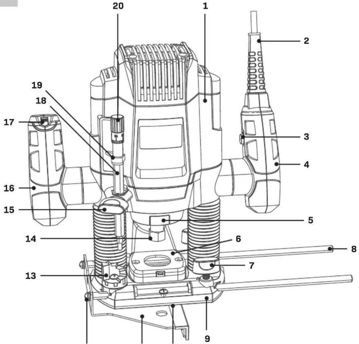
DESCRIPTION
The numbers in the text refer to the diagrams on pages 2-5.
- Machine
- Cable
- Lock-off button
- Right handle
- Spindle lock
- Vacuum cleaner attachment
- Knob for parallel guide
- Parallel guide rod
- Baseplate
- Anti scratch plate
- Parallel guide
- Bolt for parallel guide
- Depth stop revolver
- Collet nut
- Knob for depth stop
- Left handle
- Speed adjustment wheel
- Depth stop bar
- Depth stop indicator
- Depth stop fine adjustment knob
- On/off switch
- Clamping lever
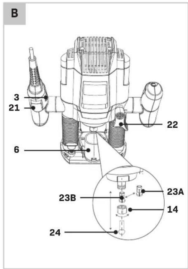
23A. Collet 8mm
23B. Collet 6mm - Router bit
- Template guide
- Bolt
- Centre pin
- Wrench
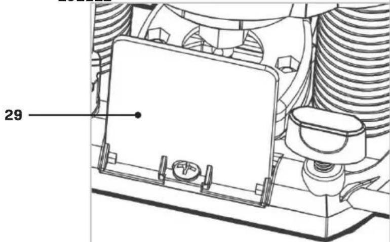
- Safety guard
30.Scale
3. ASSEMBLY
Before carrying out any work on the machine, disconnect the mains plug from the power supply.
Mounting and removing router bits (fig. B)
Only use cutters with a shaft diameter which corresponds with the size of the collet.
Only use cutters which are suited for the maximum speed of the machine.
The cutter diameter should not exceed the maximum diameter (see 'Technical specifications').
The router bits included with this machine are shown in the figure ‘package contents’.
Never tighten the collet nut, if there is no router bit in the collet; the collet may be damaged.
- Remove the safety guard (29).
- Keep the spindle lock button (5) pressed and rotate the spindle until the spindle lock fully engages.
- Loosen the collet nut (14) using the wrench (28) provided.
- Insert the shank of the router bit (24) into the collet (23) as shown on figure B. Make sure that the shank protrudes at least 3mm from the collet.
- Keep the spindle lock button (5) pressed and tighten the collet nut (14) using the wrench (28) provided.
Replacing the collet (Fig. B)
The correct size collet must be used for the corresponding router bit (cutter) type.
- Remove the safety guard (29).
- Keep the spindle lock button (5) pressed and rotate the spindle until the spindle lock fully engages.
- Loosen the collet nut (14) using the wrench (28) provided.
- Replace the collet (23).
- Keep the spindle lock button (5) pressed and tighten the collet nut (14) using the wrench (28) provided.
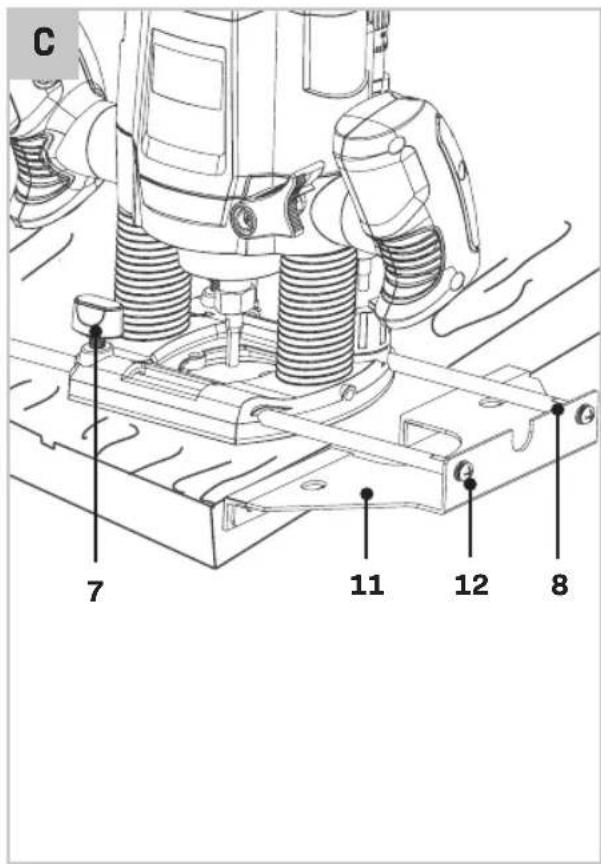
Assembling and using the parallel guide (fig. C)
The parallel guide is a useful tool for precision routing at a fixed distance from the edge of the workpiece.
- Fit the rods (8) to the parallel guide (11) using the two bolts (12) provided.
- Insert the bars (8) into the router base (9) as shown on figure C.
- Set the parallel guide to the required distance.
- Tighten the Bolt for parallel guide (12).
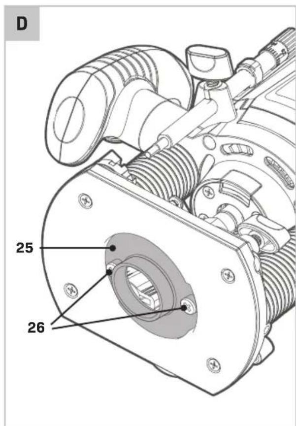
Mounting the template guide (Fig. D)
The template guide is a handy aid for cutting a pattern.
- Fit the template guide (25) to the base (9) of the router, as shown on figure D. Be aware to mount it with the flange to the bottom (workpiece) side.
- Insert the two bolts (26) from the bottom side through the template guide and tighten.
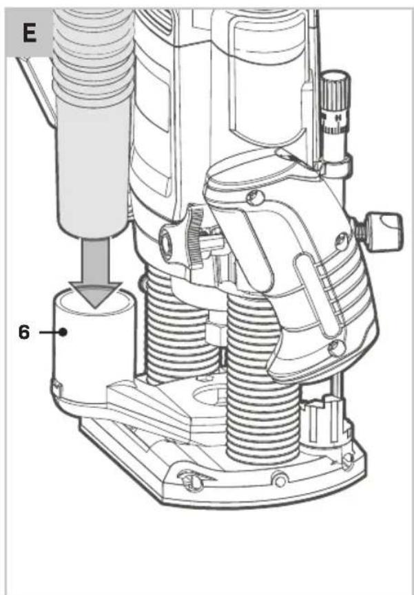
Mounting the vacuum cleaner attachment (Fig. B+E)
The vacuum cleaner attachment (6) allows you to connect a vacuum cleaner to the tool.
- Mount the vacuum cleaner attachment (6) to the base (9) of the router, as shown on figure E.
- Insert the two bolts (26) from the bottom side and tighten.
- Place the tube of your vacuum cleaner on the vacuum cleaner attachment (6).
Note: keep the dust outlet on the rear side of the machine to secure a good view on the workpiece.
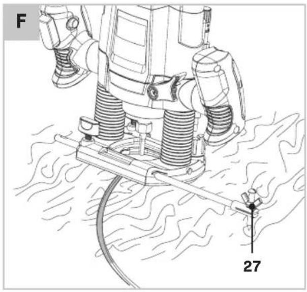
Assembling and using the centre pin (Fig. F)
- To use the centre pin, insert one guide rod (8) with the centre pin (27) attached into the holes, either side of the base plate of the router.
- Secure the guide fence rod to the router at the required length by rotating the fixing screw (12) clockwise.
4. OPERATION

Let the tool work at its own pace. Do not overload.

Carefully guide the cable in order to avoid accidentally cutting it.
Switching the machine on/off (Fig. A)
- To start the machine, press and hold the lock-off button (3) and press the on/off switch (21).
- To stop the machine, release the on/off switch (21).
Speed Preselection (Fig. A)
The required speed can be preselected with the speed adjustment wheel (17). Also during running the rotational speed can be adjusted.
1 - 2 = low speed
3 - 4 = medium speed
5 = high speed
Max = maximum speed
The required speeds depends on the material and can be determined by practical testing.
Furthermore router bits with a large diameter need a lower rotational speed.
| Material Diameter Router bit Speed stages | ||
| Hardwood | >20 mm | 1 - 2 |
| 10 - 20 mm | 3 - 4 | |
| <10 mm | 5 - max | |
| Softwood | >20 mm | 1 - 3 |
| 10 - 20 mm | 3 - 5 | |
| <10 mm | 5 - max | |
| Aluminium | >15 mm | 1 |
| >15 mm | 1 - 2 | |
| Plastic | >15 mm | 1 - 2 |
| >15 mm | 2 - 3 | |
After longer periods of working at low speed, allow the machine to cool down by running it for a few minutes at high speed with no load.
Adjusting the depth of cut (fig. G, H)
The depth of cut is the distance between the depth stop bar (18) and the depth stop revolver (13), marked as 'X' on figure G. The depth of cut can be set in two different ways as described as follows:
Adjusting the depth of cut using the scale (fig. G)
- Fit the router bit as described above.
- Loosen the knob for depth stop (15).
-
Pull the clamping lever (22) upwards, releasing the router movement.
-
Plunge the router downwards until the router bit touches the workpiece.
- Push the clamping lever (22) downwards, fixating the router movement.
- Move the indicator (19) in the zero position on the scale (30).
- Add the desired depth of cut to the starting position.
- Move the depth stop bar (18) to the desired position on the scale.
- Tighten the locking screw (28).
- Fine adjust using the depth stop fine adjustment knob (20).
- Pull the clamping lever (22) upwards and let the router return to its original position.
- After switching the router on, plunge it downwards and make the desired cut.
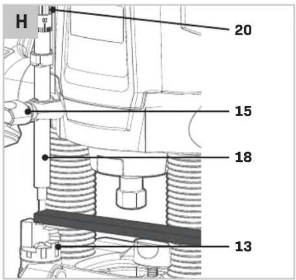
Adjusting the depth of cut using a piece of wood (fig. H)
- Fit the router bit and plunge the router downwards as described above.
- Pull the depth stop bar (18) upwards.
- Place a piece of wood with a thickness equal to the desired depth of cut between the depth stop (15) and the depth stop revolver (13).
- Tighten the knob for depth stop (15).
- Fine adjust using the depth stop fine adjustment knob (20).
- Remove the piece of wood.
- Pull the clamping lever (22) upwards and let the router return to its original position.
- After switching the router on, plunge it downwards and make the desired cut.
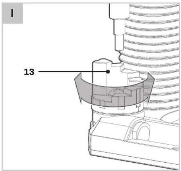
Adjusting the revolver depth stop (fig. I)
The revolver-depth stop (13) enables you to quickly choose between six different cutting depths.
These are also determined by the adjustment of the depth stop (15). For larger routing depths, it is recommended to carry out several repetitive cuts with lower removal rates.
- Adjust the required cutting depth by pressing the revolver-depth stop downwards and rotating the revolver-depth stop (13).
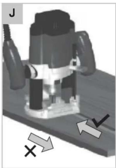
Recommended use (Fig. J, K)
- When working on outside edges, move the tool counterclockwise (Fig. J). When working on inside edges, move the tool clockwise (Fig. K).
- Depending on processing and application, router bits are available in the most different designs and qualities:
- Router bits made of high speed steel (HSS) are suitable for working with soft materials, e.g. soft wood and plastic.
- Carbide tipped router bits (HM) are particularly suitable for hard and abrasive materials, e.g. hard wood and aluminium.
- You can use the tool without a guide. This is useful for signwriting and creative work. Only make shallow cuts.
- After switching the machine on, make sure the machine reaches full speed before using it on the workpiece.
- Clamp the workpiece and make sure that the workpiece cannot slide from under the machine during the cutting activities.
- Hold the machine firmly and move it evenly over the workpiece. Do not force the machine.
- Only use cutters which do not show any signs of wear. Worn cutters have a negative effect on the efficiency of the machine.
- Always switch off the machine first before removing the plug from the wall socket.
ENVIRONMENT

and/or discarded electrical or electronic apparatus have to be collected at the appropriate recycling locations.
Only for EC countries
Do not dispose of power tools into domestic waste. According to the European Guideline 2012/19/EU for Waste Electrical and Electronic Equipment and its implementation into national right, power tools that are no longer usable must be collected separately and disposed of in an environmentally friendly way.
WARRANTY
VONROC products are developed to the highest quality standards and are guaranteed free of defects in both materials and workmanship for the period lawfully stipulated starting from the date of original purchase. Should the product develop any failure during this period due to defective material and/or workmanship then contact VONROC directly.
The following circumstances are excluded from this guarantee:
- Repairs and or alterations have been made or attempted to the machine by unauthorized service centers;
- Normal wear and tear;
- The tool has been abused, misused or improperly maintained;
- Non-original spare parts have been used.
This constitutes the sole warranty made by company either expressed or implied. There are no other warranties expressed or implied which extend beyond the face hereof, herein, including the implied warranties of merchantability and fitness for a particular purpose. In no event shall VONROC be liable for any incidental or consequential damages. The dealers remedies shall be limited to repair or replacement of nonconforming units or parts.
The product and the user manual are subject to change. Specifications can be changed without further notice.
2. INFORMATIE OVER HET APPARAAT
Bedoeld gebruik
DECLARATION OF CONFORMITY PR501AC - ROUTER
(EN) We declare under our sole responsibility that this product is in conformity with directive 2011/65/EU of the European parliament and of the council of 8 June on the restriction of the use of certain hazardous substances in electrical and electronic equipment is in conformity and accordance with the following standards and regulations:
(DE) Der Hersteller erklärt eigenverantwortlich, dass dieses Produkt der Direktive 2011/65/EU des Europäischen Parlaments und des Rats vom 8. Juni 2011 über die Einschränkung der Anwendung von bestimmten gefährlichen Stoffen in elektrischen und elektronischen Geräten entspricht. den folgenden Standards und Vorschriften entspricht:
(NL) Wij verklaren onder onze volledige verantwoordelijkheid dat dit product voldoet aan de conform Richtlijn 2011/65/EU van het Europees Parlement en de Raad van 8 juni 2011 betreffende beperking van het gebruik van bepaalde gevaarlijke stoffen in elektrische en elektronische apparatuur en in overeenstemming is met de volgende standaarden en reguleringen:
(FR) Nous déclarons sous notre seule responsabilité que ce produit est conforme aux standards et directives suivants: est conforme à la Directive 2011/65/EU du Parlement Européen et du Conseil du 8 juin 2011 concernant la limitation d'usage de certaines substances dangereuses dans l'équipement électrique et électronique.
(ES) Declaramos bajo nuestra exclusiva responsabilidad que este producto cumple con las siguientes normas y estándares de funcionamiento: se encuentra conforme con la Directiva 2011/65/UE del Parlamento Europeo y del Consejo de 8 de junio de 2011 sobre la restricción del uso de determinadas sustancias peligrosas en los equipos eléctricos y electrónicos.
(IT) Dichiariamo, sotto la nostra responsabilità, che questo prodotto è conforme alle normative e ai regolamenti seguenti: è conforme alla Direttiva 2011/65/UE del Parlamento Europeo e del Consiglio dell'8 giugno 2011 sulla limitazione dell'uso di determinate sostanze pericolose nelle apparecchiature elettriche ed elettroniche.
(SV) Vi försäkrar under vårt eget ansvar att denna produkt överensstämmer med Europaparlamentets och rådets direktiv 2011/65/EU av den 8 juni om begränsning av användningen av vissa farliga ämnen i elektrisk och elektronisk utrustning och är i överensstämmelse och enlighet med följande standarder och föreskrifter:
(DA) Vi erklærer under eget ansvar, at dette produkt er i overensstemmelse med Europa-Parlamentets og Rådets direktiv 2011/65/EU af 8. juni om begrænsning af brugen af visse farlige stoffer i elektrisk og elektronisk udstyr og overholder og er i overensstemmelse med følgende standarder og regler:
(PL) Deklarujemy na własną odpowiedzialność, że ten produkt spełnia wymogi zawarte w następujących normach i przepisach: jest zgodny z Dyrektywą 2011/65/UE Parlamentu Europejskiego i Rady z dnia 8 czerwca 2011 r. w sprawie ograniczenia stosowania niektórych niebezpiecznych substancji w sprzęcie elektrycznym i elektronicznym.
(RO) Declarăm sub responsabilitatea exclusivă că acest produs este în conformitate cu Directiva 2011/65/EU a Parlamentului și a Consiliului European din 8 iunie privind restricționarea utilizării anumitor substanțe periculoase în echipamentele electrice și electronice și în conformitate cu următoarele standarde și reglementări:
(PT) Declaramos, sob nossa exclusiva responsabilidade, que este produto está em conformidade com a directiva 2011/65/UE do Parlamento Europeu e com a do conselho de 8 de Junho sobre a restrição da utilização de determinadas substâncias perigosas em equipamento eléctrico e electrónico está em conformidade e de acordo com as seguintes normas e regulamentações:
(HU) Kizárólagos felelősségünk tudatában kijelentjük, hogy ez a termék megfelel az Európai Parlamentnek és a Tanácsnak az egyes veszélyes anyagok elektromos és elektronikus berendezésekben való alkalmazásának korlátozásáról szóló 2011/65/EU irányelvének (2011. június 8.), valamint a következő szabványoknak és jogszabályoknak:
(CS) Prohlašujeme na svou výhradní odpovědnost, že tento výrobek splňuje požadavky směrnice 2011/65/EU Evropské rady a parlamentu ze dne 8. června, která se týká omezení používání určitých nebezpečných látek v elektrických a elektronických zařízeních, a splňuje také všechny požadavky následujících norem a předpisů:
EN 62841-1, EN 62841-2-17, EN 55014-1, EN 55014-2, EN 61000-3-2, EN 61000-3-3, 2006/42/EC, 2014/30/EU, 2012/19/EU, 2011/65/EU
Zwolle, 01-04-2022 H.G.FRosberg CEO

VONROC • Lingenstraat 6 • 8028 PM Zwolle • The Netherlands

VONROC®
BUILD YOUR FUTURE
©2022 VONROC
WWW.VONROC.COM
2204-14
- UONROC
- SAFETY INSTRUCTIONS
- GENERAL POWER TOOL SAFETY WARNINGS
- Save all warnings and instructions for future reference.
- 1) Work area safety
- 2) Electrical safety
- 3) Personal safety
- ADDITIONAL SAFETY INSTRUCTION FOR ROUTERS
- Electrical safety
- MACHINE INFORMATION
- Intended use
- Vibration level
- DESCRIPTION
- ASSEMBLY
- Mounting and removing router bits (fig. B)
- Replacing the collet (Fig. B)
- Assembling and using the parallel guide (fig. C)
- Mounting the template guide (Fig. D)
- Mounting the vacuum cleaner attachment (Fig. B+E)
- Assembling and using the centre pin (Fig. F)
- OPERATION
- Switching the machine on/off (Fig. A)
- Speed Preselection (Fig. A)
- Adjusting the depth of cut (fig. G, H)
- Adjusting the depth of cut using the scale (fig. G)
- Adjusting the revolver depth stop (fig. I)
- Recommended use (Fig. J, K)
- ENVIRONMENT
- Only for EC countries
- WARRANTY
- INFORMATIE OVER HET APPARAAT
- Bedoeld gebruik
- DECLARATION OF CONFORMITY PR501AC - ROUTER
Brand : Vonroc
Model : PR501AC
Category : Router