H10 - Detector SAVS - Free user manual and instructions
Find the device manual for free H10 SAVS in PDF.


User questions about H10 SAVS
0 question about this device. Answer the ones you know or ask your own.
Ask a new question about this device
Download the instructions for your Detector in PDF format for free! Find your manual H10 - SAVS and take your electronic device back in hand. On this page are published all the documents necessary for the use of your device. H10 by SAVS.
USER MANUAL H10 SAVS
natural_image
Simple line drawing of a circular mechanical component with a central hole and two small protrusions (no text or symbols)1 Important Safeguards and Warnings
EN
This manual will help you to use the Device properly. Read the manual carefully before using the Device, and keep it well for future reference.
Operation Requirements

WARNING
- Never ignore any alarm. Failure to respond may lead to serious injury or death.
- If there is any question as to the cause of an alarm, it should be assumed that the alarm is due to an actual fire and the dwelling should be evacuated immediately.

CAUTION
- Make sure that the power supply of the device works properly before use.
- Use the device according to the operating environment.
- Only use the device within the rated power range.
- Transport, use and store the device under allowed humidity and temperature conditions.
- Prevent liquids from splashing or dripping on the device. Make sure that there are no objects filled with liquid on top of the device to avoid liquids flowing into it.
• The heat alarm is only designed for indicating the temperature, but it cannot detect gas, smoke or flames.
Installation Requirements

WARNING
Failure to properly install and operate this device will prevent proper operation of the Device and will prevent its response to fire hazards.

CAUTION
- Observe all safety procedures and wear required protective equipment provided for your use while working at heights.
- Do not expose the device to direct sunlight or heat sources.
- Keep the original packing material well because you might need it to pack the device and send it back for repair.
EN
- Make sure the application scenario conforms to installation requirements. Contact your local retailer or customer service center if there is any problem.
- All installation and operations shall conform to your local electrical safety requirements, fire protection regulations, and other relevant regulations.
Maintenance Requirements
- Do not clean the device with any cleaning products.
- Do not paint the device. Paint will seal the bents and interfere with the sensor's ability to detect temperature.
2 Introduction
2.1 Product information
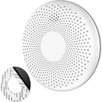
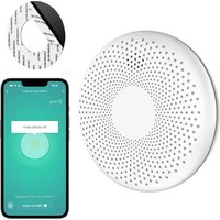
Heat Alarm (hereinafter referred to as the device) is specifically designed to continuously monitor temperature. Integrated with a high-precision thermistor and an intelligent algorithm, it triggers an alarm when a predetermined temperature is reached. It is ideal for smoky, dusty, or humid areas that may trigger false smoke alarms, e.g., kitchens where cooking fumes are present and attics, garages boiler rooms where there may be lots of dust. By using heat alarms, you can monitor these areas for a fire, without having to worry about a false alarm. Powered by a 10-year sealed battery, it provides 24/7 protection against fire for a decade.
The heat alarm is specified for Class A1 detection. Your heat alarm will sound a warning when the ambient temperature in a room is between 54°C and 65°C.
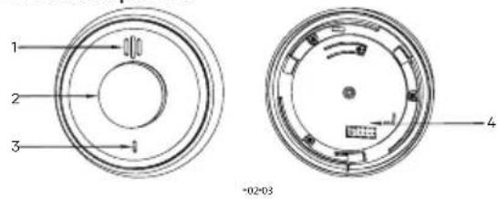
2.2 Product profile
text_image
1 2 3 4 -02-03| No. | Name | Introduction |
| 1 | Buzzer | Alarm Sound: 85dB (A) at 3 m (9.84 ft) |
| 2 | Test/Silence Button | The large central push button enables you to test and silence the alarm. By pressing the central button, you can:Verify the normal workingTemporarily stop the alarm sound |
| 3 | Indicator | Standby: Green indicator flashes once per minuteAlarm: Red indicator flashes once per second, the buzzer beeps once per secondFault: Red indicator flashes twice per minute, the buzzer beeps twice per minute |
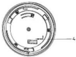
| 4 | Battery Compartment | Built-in battery, not replaceable by user |
3 Technical Information
| Specification | Introduction |
| Collection Type | Temperature |
| Sampling Period | 10s |
| Sensor Type | Thermistor |
| Alarm Type | Heat alarm, fault warning, low battery warning |
| Alarm Volume | 85dB (A) at 3 m (9.84 ft) |
| Alarm Mode | Visual and audio alarm |
| Silencing Function | Yes |
| Indicator Light | Alarm, fault and operation indicator |
| Led Instructions | Standby: Green indicator flashes once per minuteAlarm: Red indicator flashes once per second, the buzzer beeps once per secondFault: Red indicator flashes twice per minute, the buzzer beeps twice per minute |
| Battery Life | 10 years |
| Operating Voltage | 3V CR123A lithium battery (non-replaceable) |
| Detection Class | Class A1 fire detection (54°C to 65°C) |
| Operating Current | Monitoring current: ≤15uALarm current: ≤60mA |
| Operating Temperature | -10°C to +55°C (+14°F to +13°F) |
| Operating Humidity | ≤95% RH (non-condensing) |
| Color | White |
| Casing | PC |
| Dimensions | φ93.8mm × H46.9mm (φ3.69" × H1.85") |
| Weight | 115 g (0.25 lb) |
| Installation | Ceiling Mount |
| Certifications | CE |
| Compliance Standard | BS 5446-2-2003 |
4 Device Installation
4.1 Packing List
Check the package according to the following checklist. If you find device damage or any loss, contact the after-sales service.
Table 4-1 Checklist
| Name | Quantity |
| Heat Alarm 1 | |
| Self-tapping Screw | 2 |
| Expansion Bolt 2 | |
| Mounting Plate 1 | |
| User's Manual 1 |
4.2 Installation Position
In which room should the Device be installed?
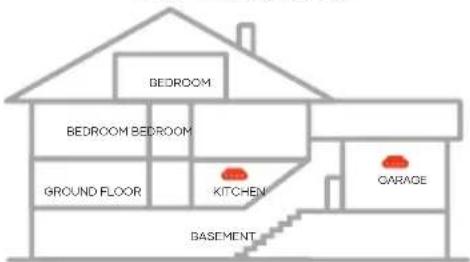
Your heat alarm is suitable for use in mobile homes and caravans. This heat alarm is not intended for any non-residential, commercial or industrial application, nor for any other purpose than described. Heat alarm is suitable for kitchens, garages, lofts, boiler rooms and laundry rooms. For the best protection, heat alarms should always be installed as part of a complete fire protection system that includes smoke alarms. Heat alarm should never be used as an alternative or replacement to smoke alarms with a view to providing early warning of smoke, fire or heat.

CAUTION
This device is intended for use in ordinary indoor locations of family living units. Construction and layout of individual dwellings will vary, so this should be regarded as a reference only. For further guidance, please check with your local fire station.
Figure 4-1 Overall layout
text_image
BEDROOM BEDROOM BEDROOM GROUND FLOOR KITCHEN GARAGE BASEMENTWhere in the room should the Device be installed?
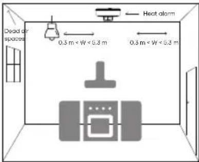
- Heat alarms should be sited on the ceiling, ideally in the center of the room.
- Site alarms 300 mm (12") at least from walls, light fittings, or other obstructions. Install your heat alarm at a distance no greater than 5.3m from the farthest wall, no greater than 5.3m from a door to any room in which a fire might start, and no greater than 5.3m from the next heat alarm.
- Alarms should not be sited within or too close to a bathroom door as steam and moisture can affect them.
- Avoid the area close to fluorescent lights as the flickering light may trigger the alarm or affect its operation.
- Ensure that the alarm is outside of any dead air spaces that occur in corners and spaces where the airflow may be blocked.
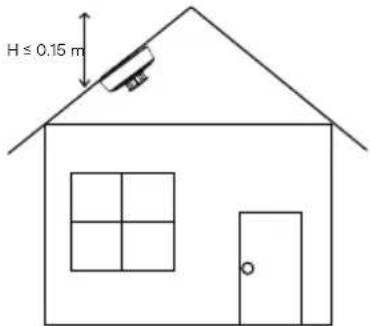
- When a heat alarm is installed in peaked and sloped ceilings, a maximum of 150 mm vertically down from the apex on the slope is required.
• The alarm should have its vents easily accessible for testing and maintenance.

WARNING
Heat alarms should not be wall mounted.
Figure 4-2 Recommended location (1)
text_image
Dead or spaces 0.3 m < W < 0.3 m Heat alarm 0.3 m < W < 0.3 mFigure 4-3 Recommended location (2)
text_image
H ≤ 0.15 m-06-07
4.3 Installation Steps
Follow below steps to install the device properly.
Step 1 Choose suitable place to install your heat alarm.
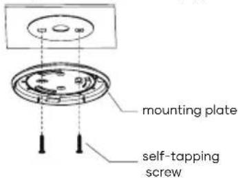
Step 2 Drill holes ( _6 mm [0.24]) into the ceiling, and then align the screw holes on the wall with the expansion bolts.
Step 3 Fix the mounting plate with self-tapping screws.
Figure 4-4 Installation step (1)
text_image
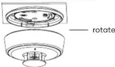
mounting plate self-tapping screwStep 4 Install the Device.
Rotate the device according to the corresponding position and direction as shown in the figure.
NOTE Please ensure it is firm.
Figure 4-5 Installation step (2)
text_image
rotate.
5 Test and Maintenance
5.1 Test
After the installation of the Device or regular maintenance, a test must be carried out to confirm that the Device is operating properly. During the testing process, the defective Device should be addressed according to "FAQ" and "Maintenance", and then tested again. If it fails to complete the test successfully, please send the Device to the manufacturer for repair.
Device self-test
Press the Test/Silence button, the buzzer will beep once and the red LED indicator light will flash once, and then the buzzer will beep continuously for two times and two cycles, accompanied by the red LED indicator flashing two times.
Silence/Pause the alarm
When the temperature concentration reaches a predetermined threshold, the indicator light flashes, and the buzzer beeps (85dB). If a false alarm is triggered, you can silence it by pressing the Test/Silence button on the device to stop the alarm sound.

WARNING
NEVER IGNORE ANY ALARM.
If an alarm is sounding, it is warning you of a potentially hazardous situation. Do not ignore it. Ignoring the alarm may result in injury or death. If your heat alarm activates and you are not absolutely certain of the source of fire, get everyone out of the house immediately.

CAUTION
You can silence this device with an infrared remote controller by pressing the button on it and the device will pause the alarm. The alarm will automatically exit silence mode after 9 minutes. Avoid receiving unintentional signals from other infrared sources (such as the remote control or other external remote control signals), which may cause abnormal alarm silence. It is also necessary to pay attention to the installation environment (where infrared signals such as televisions cannot be directly received).
Low voltage
When the battery voltage is lower than a certain threshold, indicator flashes once and the buzzer beeps once every minute until the battery is depleted. Please immediately replace the device immediately or contact technical support for advice.
5.2 Maintenance
To keep your device in good working condition, please follow these requirements.
- Simulate fire alarm test: Test the device once a week. Under normal working conditions, press the Test/Silence button to ensure that the Device can work normally. If there is a malfunction, please repair it in time. After cleaning, please install the Device and test again.
- Clean the shell: Clean the device at least once per year (recommended). Keep the Device free of dust or inserts by gently vacuuming the shell with a soft brush attachment when required. Avoid cleaning solutions on the Device to prevent the possibility of contaminating the sensor.
- Do not paint the device. Paint will seal the bents and interfere with the sensor's ability to work normally.
NOTE
When the detector stops working properly, please contact your local dealer or retailer for help.
6 Frequently Asked Questions
| Problem | Solutions |
| Your heat alarm does not sound during testing | · Check that the alarm is activated.· If testing immediately after first activating the alarm, you should allow a few seconds for the alarm to settle before testing.· Make sure you push the Test/Silence button firmly. |
| Your alarm chirps intermittently | · Check the location of your heat alarm (see "Installation Position").· Clean the heat alarm (see "Test and Maintenance"). |
| The LED indicator flashes red and the alarm sounds one beep every 60 seconds | · The device is under low battery condition, please replace the device immediately.· Please contact technical support for advice. |
7 Discard

Waste electrical products should not be disposed of your other household waste. Please dispose in an environmentally friendly manner, and strictly follow the local regulations regarding the disposal or recycling of the electrical device.

WARNING
Do not burn or throw into fire.
8 Warranty and Contact
If you need after-sales service, please contact your local dealer or retailer.
IVendor B.V.
Docterskampstraat 5
5222 AM's-Hertogenbosch
The Netherlands
+31(0)85-0043909


natural_image
Cross-sectional diagram of a circular mechanical or electrical component with labeled parts (no text or symbols beyond labels)natural_image
Circular mechanical component diagram with numbered parts (no text or symbols)natural_image
Circular mechanical component diagram with internal channels and a numbered label (4), no readable text or symbols beyond the number.2 Productspecifications
2.2 Productspecifications
NL

text_image
1 2 3