SP 5000 - Fitness Equipment Christopeit - Free user manual and instructions
Find the device manual for free SP 5000 Christopeit in PDF.

User questions about SP 5000 Christopeit
0 question about this device. Answer the ones you know or ask your own.
Ask a new question about this device
Download the instructions for your Fitness Equipment in PDF format for free! Find your manual SP 5000 - Christopeit and take your electronic device back in hand. On this page are published all the documents necessary for the use of your device. SP 5000 by Christopeit.
USER MANUAL SP 5000 Christopeit
Assembly and operating instructions
Order No.: 2281
Page: 17-30
GB
natural_image
Black and white photo of a multi-arm fitness machine with adjustable arms and legs (no visible text or symbols)INHALTSÜBERSICHT
InhaltSeite
SCHRITT 4
SCHRITT 7
SCHRITT 10
SCHRITT 11
SCHRITT 12
KONTROLLE
natural_image
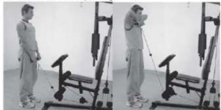
Sequence of four sequential illustrations showing a person performing a stretching or kneeling movement (no text or symbols)natural_image
Two-panel black-and-white photo showing a person performing seated exercise on a stationary chair (no text or symbols visible)natural_image
Two-panel black-and-white photo showing a person performing a fitness exercise using a machine (no text or symbols visible)Übung 5: Arm curl
natural_image
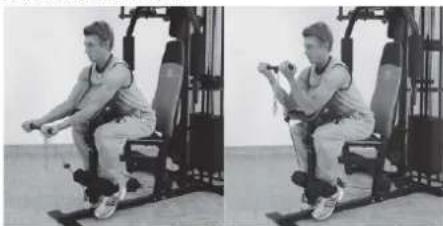
Two-panel black-and-white photo showing a person performing seated exercise using a machine (no visible text or symbols)natural_image
Two-panel black-and-white photo showing a person performing a seated exercise on a fitness machine (no text or symbols visible)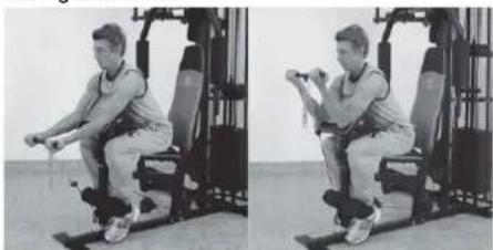
natural_image
Two-panel black-and-white photo showing a person performing a seated exercise on a stationary platform (no text or symbols visible)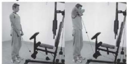
natural_image
Two-panel black-and-white photo showing a person performing a resistance exercise using a leg presser machine (no text or symbols visible)natural_image
Two-panel black-and-white photo showing a person performing a seated exercise on a fitness machine, no visible text or symbols.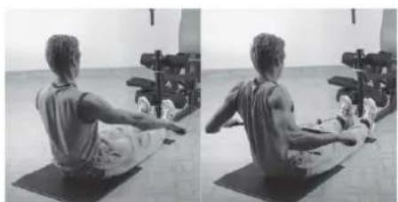
natural_image
Side-by-side black-and-white photo showing a person performing a seated core exercise on a mat, with exercise equipment in the background (no visible text or symbols)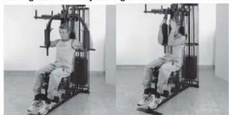
natural_image
Two-panel black-and-white photo showing a person seated in a stationary exercise machine, no visible text or symbols| 17 | Important Recommendations and safety Instructions |
| 18-25 | Assembly instructions |
| 26 | General training instructions |
| 27 | General training instructions - strength training |
| 28-30 | Parts list – spare parts List |
| 74-74 | Exploded drawing |
Attention!
Before use read the operating instructions!

DEAR CUSTOMER,
We congratulate you on your purchase of this home training sports unit and hope that we will have a great deal of pleasure with it. Please take heed of the enclosed notes and instructions and follow them closely concerning assembly and use. Please do not hesitate to contact us at any time if you should have any questions.
IMPORTANT RECOMMENDATIONS AND SAFETY INSTRUCTIONS
Our product has been tested by TÜV-GS and meets the latest and toughest safety standards. This fact does not however mean that you can fail to closely observe the following basic points.
- Assemble the equipment according to the assembly instructions and only use the individual parts enclosed for assembly of the equipment and which are listed as being specifically this equipment. Before you start assembly, check against the delivery to make sure that everything has been delivered, and check against the packing list to make sure all the parts have been enclosed.
- Check before the equipment is first used, and again at regular intervals, that all screws, bolts, nuts and other connections have been done up tightly, to ensure that your training equipment is in a safe operating condition at all times. This is especially true for the cable system. Before each workout should ropes, carbine hook and train accessories are checked for proper mounting and any signs of wear. If misaligned, wear and tear is to be immediately recognizable traces of an exchange the affected parts are required.
- Place the equipment on a dry, level surface and protect it against damp and wetness. If you wish to protect the area underneath the equipment against damage from pressure or from becoming dirty or the like, we recommend that you place a suitable non-slip item under the equipment (such as a rubber mat or sheet of wood).
- Always wear training clothing and shoes that are suitable for fitness training when you are doing training work on the equipment. The clothing must be of a type that will not hang down during training due to its shape (e.g., length). Shoes should be selected for their suitability when using the training equipment, primarily so that they provide a secure grip for the foot and have a non-slip sole. When descending from the dip bars (Exercise-manual), make sure that you find a safe standing position on the foot rests of the stepper. Go down slowly.
- Remove any objects from a vicinity of 2 meters avound the equipment before you start any training work.
-
In general, you should consult your doctor before starting targeted training work. He can make a definitive statement to the maximum exertion (pulse rate, wattage, duration of training, etc.) you can set for yourself and can also give you detailed information with respect to the correct body position during training, your training target, and questions of diet. It is to take care that this item is not useable for therapeutic purpose. Exercise never after heavy meals.
-
Only carry out training work on the equipment when it is in perfect working order. Only use original spare parts in the event of a repair.
- If it has not been explicitly stated otherwise in the instructions, the equipment may only be used by one person for training.
- If you experience giddiness, nausea, chest pains or other abnormal symptoms, stop the training at once and see a doctor.
- In general, sports training equipment is not a toy. It may only be used in an appropriate manner and by persons who have been suitably informed or instructed.
- Children, invalids and the handicapped should only use the equipment in the presence of another person who can provide assistance and instruction.
- Always pay attention that you or any other persons never bring parts of the body in close proximity to any parts of the equipment that are still moving.
- When making settings for any adjustable parts, check that they are in the right position and also check the marked maximum setting.
- Do not use strong solvents for cleaning, and only use the tools supplied, or suitable ones of your own, for any repairs that may be required.
- Please dispose of the packaging and any parts that have to be replaced subsequently (all parts for the unit) at suitable collecting points or containers with a view to saving the environment.
- This device has been tested and certified according to EN ISO 20957-1:2014-05, EN ISO 20957-4:2017-03 and EN 957-2:2003-09 according to class H (home use). The maximum permissible load (=user weight) is specified as 130 kg.
- The assembly and operating instructions is part of the product. If selling or passing to another person the documentation as must be provided with the product.
ASSEMBLY INSTRUCTIONS
Before beginning assembly, be sure to observe our recommendations and safety instructions. Some parts are pre assembled.
STEP 1
Installation of front foot (1), rear foot (2) and guide bars (10).
-
Put the front foot (1) and rear foot (2) on an even floor in the right way together. (Attention: According to assembly version whether dips- and step-unit left or right, the rear foot (2) must be mounted into appropriate position.)
-
Put the guide bars (10) (ends with holes) into the appropriate position of rear foot (2) and screw front foot (1), rear foot (2) and guide bars (10) with screw M10x70 (112), Adjusting plate (134), washer 10//20 (118) and self locking nut M10 (124) tightly. Ensure that the screws are put through the holes of guide bars so that they are blocked in bottom position.
-
Then put the screw caps for M10 (131) onto all M10 screw heads and nuts.
STEP 2
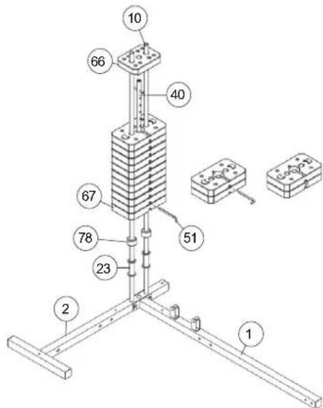
Installation of weight plates (66+67) at guide bars (10).
- Slide the weight supports (23) onto the guide bars (10).
- Then put the rubber buffer (78) onto the guide bars (10). (If you bought the option weight set Art.-No. 9388 you have to put on the 2 weights of option set instead of the weight supports, But firstly you have to slide onto the guide bars (10) the rubber buffer (78)).
- Place the 11 weights (67) onto the guide bars (10) as you can see on step drawing 2.
- Put the weight disc bar (40) into the weight plates (67) and put at least the smaller first weight (66) on.
- To adjust the loaded weights use the weight selector bar (51) and put it into the weight disc bar (40) in desired position.
STEP 3
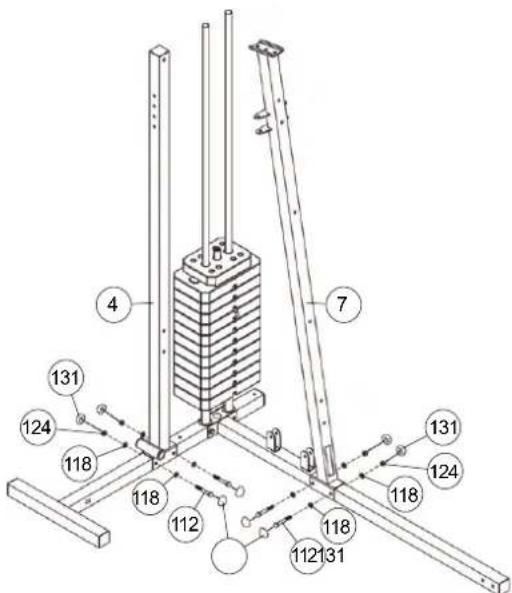
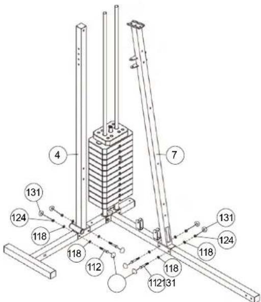
Installation of supports 1+2 (4+7) at front foot and rear foot (1+2).
- Put the support 1 (4) into the appropriate position of rear foot (2) and tighten it firmly by using screw M10x70 (112), washer 10//20 (118) and self locking nut M10 (124).
- Put the support 2 (7) into appropriate position of front foot (1) and tighten it firmly by using screws M10x70 (112), washers 10//20 (118) and self locking nut M10 (124).
- Then put the screw caps for M10 (131) onto all M10 screw heads and nuts.

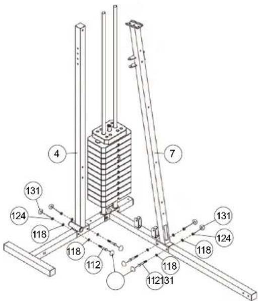
STEP 4
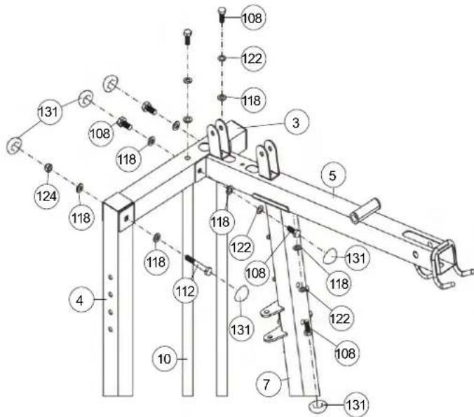
Installation of tabular guide holder (3) and top cross beam (5) at supports 1+2 (4+7).
- Place the tabular guide holder (3) onto the ends of guide bars (10) and support 1 (4).
- Screw the tabular guide holder (3) at guide bars (10) tightly by using screw M10x20 (108), spring washers for M10 (122) and washers 10//20 (118). Screw two screws (108) with the washers (118) to decorate the thread holes of the support 1 (3).
- Connect the end of support 1 (4) with tabular guide holder (3) und screw them together by using screw M10x70 (112), washer 10//20 (118) and self locking nut M10 (124).
- Put the top cross beam (5) in appropriate position onto the support 2 (7) and tighten it firmly by using screw 10x20 (108), spring washer for M10 (122) and washers 10//20 (118) at support 2 (7).
- Screw tightly the top cross beam (5) at tabular guide holder (3) by using screw M 10x20 (108), spring washer for M10 (122) and washers10//20 (118).
- Then put the screw caps for M10 (131) onto all M10 screw heads and nuts.
STEP 5
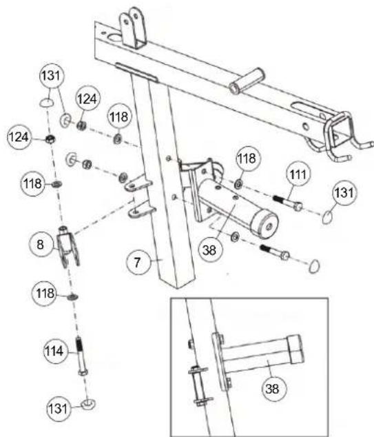
Installation of bench press support (38) and cable pulley holder 1 (8) at support 2 (7).
- Place the bench press support (38) in appropriate position at support 2 (7) and screw these parts together by using screw M10 x 65 (111), washers 10//20 (118) and self locking nut M10 (124).
- Put the cable pulley holder 1 (8) into the holder at support 2 (7) and screw them together by using screw M10x80 (114), washer 10//20 (118) and self locking nut M10 (124). Attention! The cable pulley holder 1(8) should turn easy when it is assembled.
- Then put the screw caps for M10 (131) onto all M10 screw heads and nuts.
STEP 6
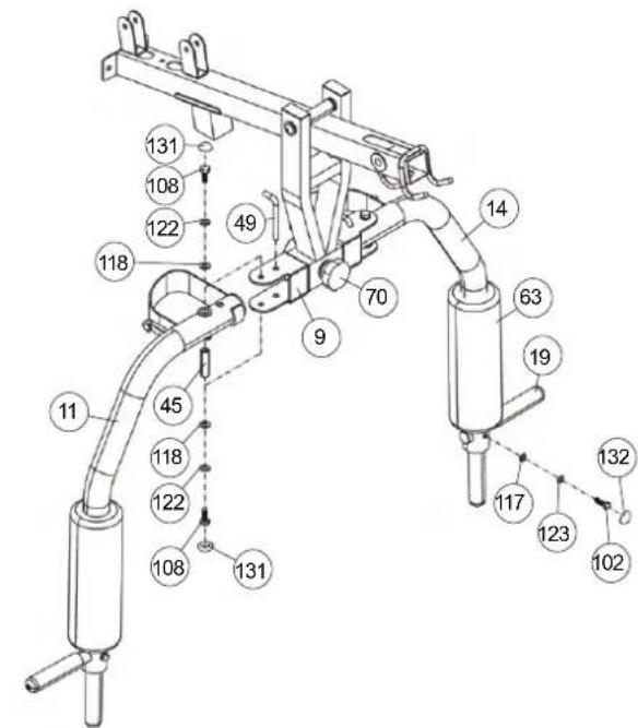
Installation of butterfly arm holder (9) at top cross beam (5).
- Place the butterfly arm holder (9) in appropriate position at top cross beam (5), so that the holes with steel bearings are align and slide the axle 2 (39) through the butterfly arm holder (9) and top cross beam (5).
- Secure the axle 2 (39) by using screw M8x15 (99), spring washers for M8 (123) and washers 8//28 (121) on both sides.
- For butterfly exercising you have to secure the butterfly arm holder (9) with handgrip bolt 2 (70) and washer 10//38 (120) at bench press support (38).

STEP 7
Installation of butterfly arms (11+14) at butterfly arm holder (9) and foam rubber roll (63) and hand grips (19).
- Put the butterfly shafts (45) into the holder of butterfly arm left and right (11+14) and place the butterfly arms (11+14) in right position into the appropriate holder of butterfly holder (9).
- Screw the butterfly arms (11+14) at butterfly arm holder (9) tightly by using screw M10x20 (108), spring washer for M10 (122) and washer 10//20 (118) on bottom and top side.
- Slide the foam rubber roll (63) with help of a little bit soap water onto the butterfly arms (11+14).
- Place the hand grips (19) into appropriate holder of butterfly arm left and right (11+14) and screw them tightly by using screw M8x30 (102), washer 8//16 (117) and spring washer for M8 (123).
- For bench press exercising secure the butterfly arms left and right (11+14) with locking pins (49) at butterfly holder (9) and screw out the handgrip bolt 2 (70) of bench press support (9).
- For butterfly exercising secure the butterfly arm holder (9) with hand grip bolt 2 (70) at bench press support (38) and take out the locking pins (49) from butterfly arms (11+14).
- Then put the screw caps for M10 (131) onto all M10 screw heads and nuts and the screw caps(132) for M8 onto all M8 screw heads and nuts.
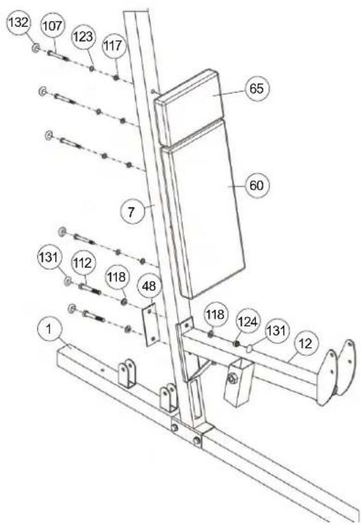
STEP 8
Installation of the back pad (60) and leg curler holder (12) at support 2 (7).
- Adjust the back pad (60) on support 2 (15) so that the threaded holes in the rear of the back pad (60) are align with the holes in support 2 (7) and screw it tightly by using screw M8 x 70 (107), spring washer for M8 (123) and washer 8//16 (117).
- Then mount the head pad (65) in the same way as the back pad (60).
- Place the leg curler holder (12) in appropriate position at support 2 (7), so that the holes are align and screw it tightly by using screw M10x70 (112), adjusting plate (48), washers 10//20 (118) and self locking nut M10 (124).
- Then put the screw caps for M10 (131) onto all M10 screw heads and nuts and the screw caps(132) for M8 onto all M8 screw heads and nuts.
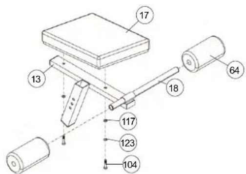
STEP 9
Installation of seat pad (17) and round pad holder (18) at seat support frame (13).
- Adjust the seat pad (17) on seat support frame (13) so that the threaded holes in the rear of seat pad (17) are align with the seat support frame (13) and screw it tightly by using screw M8x45 (104), spring washer for M8 (123) and washer 8//16 (117).
- Slide the round pad holder (18) into the seat support frame (13) in middle position.
- Slide two black foam rubber roll (64) onto the ends of round pad holder (18).

STEP 10
Installation of seat frame (13) at leg curler support (12) and standing plates (47) at front foot (1).
- Slide the seat frame (13) into the appropriate holder of leg curler holder (12) and secure it into desired position by using the quick lock knob (74). (Note: to screw in the quick lock knob (8), the treaded hole in the leg curler support (12) and one of the holes in the seat frame (13) must be aligned. The setting of the seat can be adjusted as desired later. For this, the quick lock knob (8) must be loosened by only a few revolutions, the cap of the lock must be pulled away and the seat adjusted. Then secure the new setting by tightening the quick lock knob (8).)
- Place the standing plates (47) in front of the holder at front foot (1) and screw them tightly by using screw M10x75 (113), washer 10//20 (118) and self locking nut M10 (124).
- Then put the screw caps for M10 (131) onto all M10 screw heads and nuts.
STEP 11
Installation of leg curler (15) and arm curl pad (20) at leg curler holder (12).
- Put the leg curler (15) with pre-assembled steel bearings 1 (44) into the appropriate holder of leg curler holder (12) and screw it tightly by using screw M10x90 (115), washer 10//20 (118) and self locking nut M10 (124), Attention, the leg curler (15) should turn easy when it is assembled.
- Slide the round pad holder (18) into the holder of leg curler (15) in middle position and slide two red foam rubber rolls (64) onto the ends of round pad holder (18).
- Adjust the arm curl pad (20) on arm curl stand (16) so that the threaded holes in the rear of arm curl pad (20) are align with the arm curl stand (16) and screw it tightly by using screw M8x20 (101), spring washer for M8 (123) and washer 8//16 (117).
- The arm curl stand (16) with pre-assembled arm curl pad (20) could be mounted in desired position at leg curler (15) and secured by using the hand grip bolt 1 (69).
- To secure the position of leg curler (15) please slide the long safety bracket (52) through the aligned holes of leg curl holder (12) and leg curler (15).
- Then put the screw caps for M10 (131) onto all M10 screw heads and nuts and the screw caps(132) for M8 onto all M8 screw heads and nuts.
STEP 12
Installation of forearm pad (61), small back pad (62) and handgrip 2 (30) at dipping bar (25) and support 1 (4).
- Adjust the small back pad (62) on dipping bar (25) so that the threaded holes in the rear of small back pad (62) are align with dipping bar (25) and screw it tightly by using screw M8x20 (101), spring washer for M8 (123) and washer 8//16 (117).
- Adjust the forearm pad (61) on dipping bar (25) so that the threaded holes in the rear of forearm pad (61) are align with dipping bar (25) and screw it tightly by using screw M8x55 (105), spring washer for M8 (123) and washer 8//16 (117).
- Place the hand grips (30) into appropriate holder of dipping bar (25) and screw them tightly by using screw M10x20 (108), spring washer for M10 (122) and washer 10//20 (118).
- Put the pre-assembled dipping bar (25) into appropriate holder of support 1 (4) and screw it tightly into desired position by using screw M10x70 (112), washer 10//20 (118) and self locking nut M10 (124).
- Then put the screw caps for M10 (131) onto all M10 screw heads and nuts and the screw caps (132) for M8 onto all M8 screw heads and nuts.
STEP 13
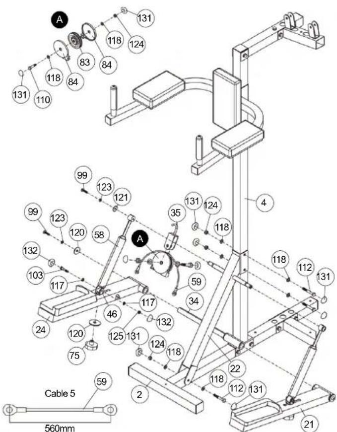
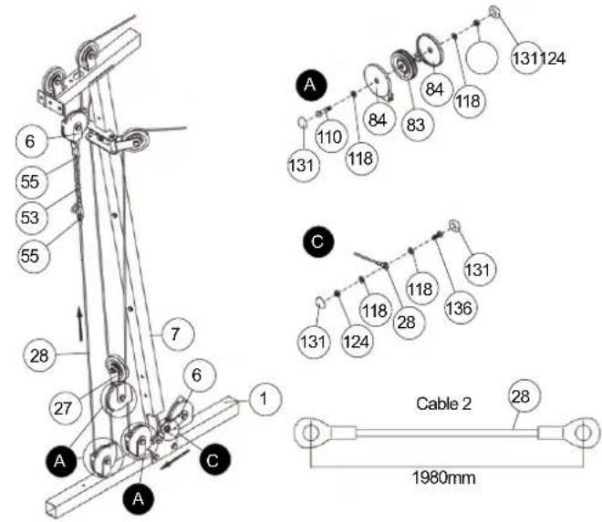
Installation of Stepper and Crossbar (22) at support 1 (4).
- Place the crossbar (22) into appropriate position at support 1 (4) and rear foot (2), so that the holes are align and screw it tightly by using screw M10x70 (112), washers 10//20 (118) and self locking nut M10 (124). (Perhaps you have to loosen the connection point of support 1 (4) and rear foot (2) a little bit to mount crossbar easy.)
- Put the left and right pedal (21+24) in right direction at appropriate holder at support 1 (4), that the steel bearings align and slide the axle 1 (34) through. Secure the axle 1 (34) by using screw M8x15 (99), spring washer for M8 (123) and washer 8//38 (120) on both ends of axle.
- Put the hydraulic cylinder (58) with top side onto the holder of crossbar (22) and secure this position by using screw M8x15 (99), spring washer for M8 (123) and washer 8//28 (121).
- Screw the bottom end of cylinder (58) at the holder for cylinder (46) by using screw M8x40 (103), washer 8//16 (117) and self locking nut M8 (125). Ensure that the cylinder (58) can turn at holder a little bit.
- Insert the holder for hydraulic cylinder (46) from top side trough the pedal left and right (21+24) and connect the holder (46) into desired position by using handgrip nut (75) and washer 10//38 (120). You can adjust the stepper resistance at holder (46) by choosing different positions at pedal left and right (21+24). (Note! The selectable positions for the mounts for hydraulic cylinders (26) are specified by holes in the foot pedals (10) and (11). The setting of the mount (26) should be in both foot pedals (10) and (11) always the same. The settings can be changed later at any time depending on the desired load. The closer the setting position to the axis (34), the lighter the stepper resistance for stepper training.)
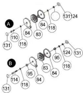
- Put a cable roller unit as figure „A“ show together, put the cable 5 (59) over the pulley (83) and connect this at cable pulley holder incl. hook (35) in a way that the cable pulley can roll easy.
- Insert the cable pulley holder incl. hook (35) into the welded holder at crossbars' (22) bottom side and connect the ends of cable 5 (59) with the pedal left and right (21+24).
- Then put the screw caps for M10 (131) onto all M10 screw heads and nuts and the screw caps(132) for M8 onto all M8 screw heads and nuts.
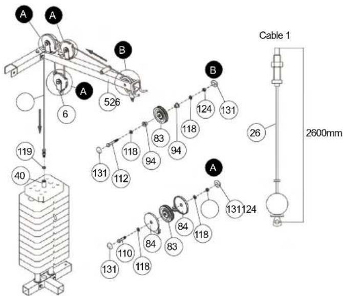
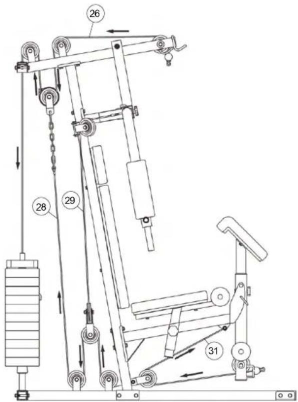
STEP 14
Installation of cable 1 for latissimus (26) with cable pulley units. Please note following situation regarding the cable pulley units: The cables have to put on the cable pulleys (83) and should covered on both sides with cable pulley covers (84) that the input and output of cable is leaded. The cable pulley units have to install at the same time with cables at right position.
- Put the cable 1 (26) as showed in Step 14 drawing through the top cross beam (5), screw the screw end of cable 1 (26) with washer 12//24 (119) into the weight disk bar (40) and secure the screw with nut. (The cable system can be finely adjusted on this cable screw. The rope screw must always be screwed in at least 12mm deep and additionally countered by the nut.)
- Take cable 1 (26) and a cable pulley unit as showed in figure „B“ (without cable pulley cover) with screw M10x70 (112), washer 10//20 (118), plastic bushing for pulley (94) and nut M10 (124). Insert the cable pulley (83) into the top cross beam (5), position the plastic bushing (94) from outer side of top cross beam (15) and screw in tightly.
- Put a cable roller unit as figure „A“ shows together with screw M10x45 (110), washer (118) and self locking nut (124), insert the cable 1 (26) and connect this at top cross beam (5).
- Take cable 1 (26) and a cable pulley unit as showed in figure „A“ with screw M10x70 (112), washer 10//20 (118), plastic bushing for pulley (94) and nut M10 (124) and attach it at cable pulley holder 2 (6).
- Then put the screw caps for M10 (131) onto all M10 screw heads and nuts.
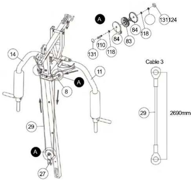
STEP15
Installation of cable 3 for butterfly (29) with cable pulley units.
- Connect the both ends of cable 3 (29) with the appropriate holder at butterfly arm left and right (11+14).
- Put two cable roller units as figure „A“ shows together with screw M10x45 (110), washer (118) and self locking nut (124), insert the cable 3 (29) and connect them at cable pulley holders 1 (8) in a way that the cable pulley can roll easy.
- Put a cable roller unit as figure „A“ shows together with screw M10x45 (110), washer (118) and self locking nut (124), insert the cable 3 (29) and connect this at twin cable pulley holder (27) in a way that the cable pulley can roll easy.
- Then put the screw caps for M10 (131) onto all M10 screw heads and nuts.
STEP 16
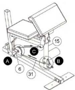
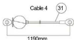
Installation of cable 4 for leg curler (31) with cable pulley units.
- Pull cable 4 (31) through the big hole of leg curler (15) and connect the end of cable 4 (31) at appropriate holder on bottom side of leg curler holder (12) by using screw M10x40 (136), washer 10//20 (118) and self locking nut M10 (124) as showed in figure „C“.
- Take cable 4 (31) and a cable pulley unit as showed in figure „B“ with screw M10x80 (114), washer 10//20 (118), plastic bushing for pulley (95) and nut M10 (124). Insert the cable pulley (83) with cable pulley cover (84) into the leg curler (15) and position the plastic bushing (95) from outer side of leg curler (15).
- Put a cable roller unit as figure „A“ shows together with screw M10x45 (110), washer (118) and self locking nut (124), insert the cable 4 (31) and connect this at cable pulley holder 1(8) in a way that the cable pulley can roll easy.
- Then put the screw caps for M10 (131) onto all M10 screw heads and nuts.
flowchart
graph TD
    A["Node A"] -->|131| B["Node B"]
    A -->|110| B
    A -->|118| B
    A -->|84| B
    A -->|83| B
    A -->|84| B
    A -->|118| B
    A -->|131| B
    B -->|114| C["Node B"]
    B -->|118| C
    B -->|95| C
    B -->|84| C
    B -->|83| C
    B -->|84| C
    B -->|95| C
    B -->|124| C
    B -->|118| C
    B -->|131| C
STEP 17
Installation of cable 2 (28) with cable pulley units.
- Pull cable 2 (28) through the big hole of support 2 (7) and connect the end of cable 2 (28) at cable pulley holder 2 (6) by using screw M10x25 (109), washer 10//20 (118) and self locking nut M10 (124) as showed in figure „C“.
- Put two cable roller unit as figure „A“ shows together with screw M10x45 (110), washer (118) and self locking nut (124), insert the cable 2 (28) and install these units at holder of front foot (1) in a way that the cable pulley can roll easy.
- Put a cable roller unit as figure „A“ shows together with screw M10x45 (110), washer (118) and self locking nut (124), insert the cable 2 (28) and connect this at twin cable pulley holder (27) in a way that the cable pulley can roll easy.
- Take cable 2 (28) and enlarge it with 8 links chain (53) and two carbine hooks (55) and connect cable 2 (28) with cable pulley holder 2 (6), which is pre-assembled at cable 1 (26). (Note: To get a smooth sliding cable system, you may adjust the cable system at 8 links chain (53) with carbine hooks (55) through setting them into another position.)
- Then put the screw caps for M10 (131) onto all M10 screw heads and nuts.
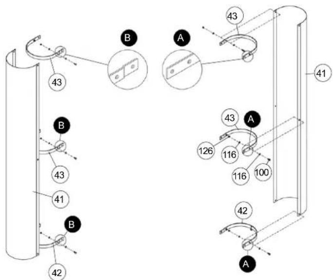
STEP 18
Installation of weight casing (41) with weight casing support (42) and bending plate (43).
- Connect the weight casing support (42) and bending plate (43) at appropriate position of weight casing (41) by using screw M6x16 (100), washer 6//12 (116) and self locking nut M 6 (126). Note, that the weight casing supports (42) and bending plates (43) have to mount into the right position as showed in Step 18 drawing.
STEP 19
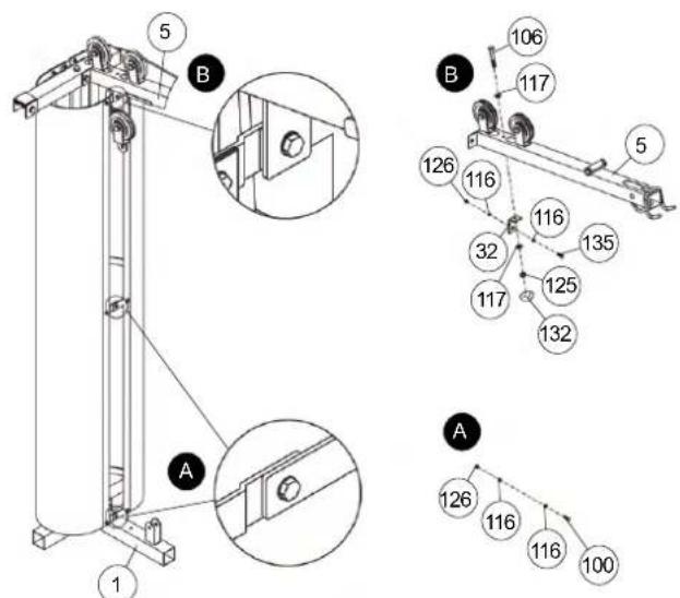
Installation of weight casing (41) with supports (42+43) at L-plate (32) and rear foot (2).
- Put the weight casing (41) with pre-assembled weight casing support (42) into the holes of rear foot (2). Get the end of opposite weight casings supports (42) and bending plates (43) together and screw them tightly by using screw M6x16 (100), washer 6//12 (116) and self locking nut M6 (126) as showed in figure „A“.
- Put the L-plate (32) under the top cross beam (5) into appropriate position and screw it tightly by using screw M8x65 (106), washer 8//16 (117) and self locking nut M8 (125) as showed in figure „B“.
- Connect the upper bending plate connection additionally at L-plate (32) by using screw M6x20 (135), washer 6//12 (116) and self locking nut M6 (126).
- Then put the screw cap for M8 (132) onto the M8 nut.

STEP 20
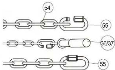
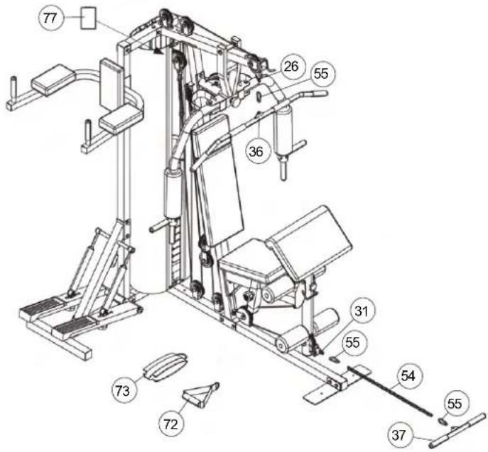
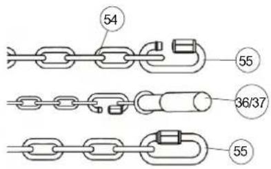
Installation of latissimus bar (36) and curl bar (37).
- Connect the latissimus bar (36) at cable 1 (26) by using carbine hook (55). To storage the latissimus bar (36) you can put it on the appropriate holder in front of the top cross beam (5).
- Connect the curl bar (37) at cable 4 (31) by using the 22 links chain (54) and carbine hooks (55). (When you use leg curler for exercising you should take away the curl bar (37) with chain (54).
- Depends on exercising you can use the handgrip (72) instead of latissimus bar (36) or the ankle strap (73) instead of curl bar (36).
- Attach the productlabel (77) to the top of the bending plates (43). To do this, remove the protective film from the adhesive strip on the back of the productlabel (77). Place it on top of the bending plates (43) on the right or left side and push slightly so that the adhesive strip catches.
Important-Safety-Information for using carbine hooks.
Loose the screw nut of C-hook(55) and put the chain (54) into the C-hook (55).
Put the cables' end or pull bars (36-37) into the C-hook (55).
Screw the nut of carbine hook (55) tightly and ensure that it is closed.
Attention!
Before start exercising ensures that the 5 carbine hooks (55) are closed tightly.

CHECKS
- Check the correct installation and function of all screwed and plug connections. Installation is thereby complete.
- Before starting training, ensure that the recommended safety clearances are maintained to other objects. To secure a particular position of the machine, the machine can be fastened firmly to the floor using bolts and plugs, which you must obtain yourself. Holes are provided for this purpose in the tubes which have direct contact with the floor.
- When using the machine, particularly the dipping bar, always be sure to wear suitable headwear and clothes. This must protect against catching hair or clothing and trapping hair or clothing in the moving parts of the machine.
- When everything is in order, familiarise yourself with the machine with light weights. The weights have to secure with weight selector bar (51). Maximum load of weight: 70Kg.
You must consider the following factors in determining the amount of training effort required in order to attain tangible physical and health benefits.
INTENSITY
The level of physical exertion during training must exceed the point of normal exertion, without going beyond the point of breathlessness and/or exhaustion. A suitable reference value can be the pulse. With each training session, the condition increases and therefore the training requirements should be adjusted. This is possible by extending the duration of the training, increasing the level of difficulty or changing the typ training.
TRAINING HEART RATE
To determine the training heart rate, you can proceed as follows. Please note that these are guide values. If you have health problems or are unsure, consult a doctor or fitness trainer.
01 Maximum heart rate calculation
The maximum pulse value can be determined in many different ways, since the maximum pulse depends on many factors. You can use the main-formula for the calculation (maximum heart rate = 220 - age). This formula is very general. It is used in many home sport products to determine the maximum heart rate. We recommend the Sally-Edwards-formula. This formula calculates the maximum heart rate more precisely and takes gender, age and body weight into account.
Sally-Edwards-formula:
Men:
Maximum heart rate = 214 - (0.5 x age) - (0.11 x body weight)
Women:
Maximum heart rate = 210 - (0.5 x age) - (0.11 x body weight)
02 Training heart rate calculation
The optimal training heart rate is determined by the goal of the training.
Training zones were defined for this.
Health - Zone: Regeneration and Compensation
Suitable for: Beginners
Type of training: very light cardio training
Goal: recovery and health promotion. Building the basic condition.
Training heart rate = 50 to 60% of the maximum heart rate
Fat-Metabolism - Zone: Basics endurance training 1
Suitable for: beginners and advanced users
Type of training: light cardio training
Goal: activation of fat metabolism (calorie burning). improvement in endurance performance.
Training heart rate = 60 to 70% of the maximum heart rate
Aerobic - Zone: Basics endurance training 1 to 2
Suitable for: beginners and advanced
Type of training: moderate cardio training.
Goal: Activation of the fat metabolism (calorie burning), improving aerobic performance, Increase in endurance performance.
Training heart rate = 70 to 80% of the maximum heart rate
Anaerobic - Zone: Basics endurance training 2
Suitable for: advanced and competitive athletes
Type of training: moderate endurance training or interval training
Goal: improvement of lactate tolerance, maximum increase in performance.
Training heart rate = 80 to 90% of the maximum heart rate
Competition - Zone: Performance / Competition Training
Suitable for: athletes and high-performance athletes
Type of training: intensive interval training and competition training /
Goal: improvement of maximum speed and power.
Attention! Training in this area can lead to overloading of the cardiovascular system and damage to health.
Training heart rate = 90 to 100% of the maximum heart rate
Sample calculation
Male, 30 years old and weighs 80 kg. I am a beginner and would like to lose some weight and increase my endurance.
01: Maximum pulse - calculation
Maximum heart rate = 214 - (0.5 x age) - (0.11 x body weight)
Maximum heart rate = 214 - (0.5 x 30) - (0.11 x 80)
Maximum pulse = approx. 190 beats/min
02: Training heart rate calculation
Due to my goals and training level, the fat metabolism zone suits me best.
Training heart rate = 60 to 70% of the maximum heart rate
Training heart rate = 190 x 0.6 [60%]
Training heart rate = approx. 114 beats/min
After you have set your training heart rate for your training condition of? Once you have identified goals, you can start training. Most of our endurance training equipment have heart rate sensors or are heart rate belt compatible. So you can check your heart rate on the monitor during the workouts. If the pulse rate is not shown on the computer display or you want to be on the safe side and want to check your pulse rate, which could be incorrectly displayed due to possible application errors or similar, you can use the following tools:
a. Pulse measurement in the conventional way (sensing the pulse beat, e.g. on the wrist and counting the beats within a minute).
b. Heart rate measurement with suitable and calibrated heart rate measuring devices (available from medical supply stores).
c. Heart rate measurement with other products such as heart rate monitors, smartphones....
FREQUENCY
Most experts recommend the combination of a health-conscious diet, which must be adjusted according to the training goal, and physical exercise three to five times a week. A normal adult needs twice a week exercise to maintain its current condition. To improve his condition and change his body weight, he needs at least three training sessions per week. Ideal of course is a frequency of five training sessions per week.
TRAINING PLAN
Each training session should consist of three training phases: "warmup phase", "training phase" and "cool-down phase". In the "warm-up phase" the body temperature and the oxygen supply should be increased slowly. This is possible through gymnastic exercises over a period of five to ten minutes. After that you start with actual training "training phase". The training load should be adapted according to the training heart rate. In order to support the circulation after the training phase and to preventaching or strained muscles later, it is necessary to follow the training phase with a cool-down phase. This should be consist of stretching exercises and/or light gymnastic exercises for a period of five to ten minutes.
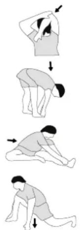
Example - stretching exercises for the warm-up and cool-down phases
Start your warm up by walking on the spot for at least 3 minutes and then perform the following gymnastic exercises to the body for the training phase to prepare accordingly. The exercises do not overdo it and only as far run until a slight drag felt. This position will hold a while.
natural_image
Sequence of four sequential illustrations showing a person performing a stretching or kneeling movement (no text or symbols)Reach with your left hand behind your head to the right shoulder and pull with the right hand slightly to the left elbow. After 20sec. switch arm.
Bend forward as far forward as possible and let your legs almost stretched. Show it with your fingers in the direction of toe. 2 x 20sec.
Sit down with one leg stretched out on the floor and bend forward and try to reach the foot with your hands. 2 x 20sec.
Kneel in a wide lunge forward and support yourself with your hands on the floor. Press the pelvis down. Change after 20 sec leg.
MOTIVATION
The key to a successful program is regular training. You should set a fixed time and place for each day of training and prepare yourself mentally for the training. Only train when you are in the mood for it and always have your goalin view. With continuous training you will be able to see how you are progressing day by day and are approaching your personal training goal bit by bit.
GENERAL TRAINING INSTRUCTIONS - STRENGTH TRAINING
RECOMMENDATION
- Before training, you should warm up the body with light exercises with weights. Stretching exercises and gymnastic exercises should only be made after training in order to reduce muscle tone and to achieve better regeneration.
- You should also read the information and safety recommendations in the assembly and operating instructions.
- The exercises should be coordinated in such a way that between the individual sets, depending on the desired training (hypertrophy - maximum strength training - strength endurance) a break of (60 seconds - 120 seconds - 30 seconds) is inserted.
- Don't overestimate yourself and choose your weights according to your physical condition. Increase slowly and never train to the pain limit, especially if you are a beginner.
- Select the exercise units according to the illustrations, your physical needs and the possibilities of the available equipment.
- A minimum training duration of 45 to 60 minutes and depending on your condition is recommended.
- Choose your training days carefully beforehand (Mon - Wed - Fri) and prepare yourself well in terms of your attitude. 3 training days per week are highly recommended. You will experience a physical and muscular increase.
- Furthermore, breathing is of crucial importance, when training with weights you should exhale during exertion, e.g. when lifting and pressing loads. Always breathe in as you release.
- Ensure correct posture to avoid injuries.
- After your workout, cool down to relax your muscles by stretching the trained muscle groups.
EXAMPLES
Training for beginners:
[ Strength endurance > Hypertrophy > Strength endurance > Hypertrophy > Maximum strength
Strength endurance ]
Training sets: 3
Reps: 20 to 25
Breaks: 30 sec
Muscle groups: max. 3 to 5
(e.g. chest - triceps - shoulder - biceps - abdominal )
Advanced training:
[ Hypertrophy > Maximum Strength
Hypertrophy > Strength endurance > Hypertrophy > Maximum strength ]
Training Sets:5
Reps: 10
Breaks: 60 sec
Muscle groups: max. 4
(e.g. chest - triceps - abdominal - legs or latissimus - biceps - deltoid - stepper)
Movement execution:
01 Hypertrophy
lift the weight up in 1 sec / lower the weight in 3 sec.
02 Endurance
lift the weight up for 2 seconds / lower the weight down for 2 seconds.
03 Maximum power
explosively lift the weight up / lower the weight down for 2-3 sec.
Training rhythm:
Monday - Wednesday - Friday - Sunday - Tuesday - Thursday - Saturday ...
Handle variants:
lower grip - upper grip - neutral grip
Step position:
Feet hip to shoulder width - knees slightly bent - stomach and buttocks tightly tense - chest slightly raised - head in extension of the spine - look straight ahead
Postures:
Basic position - feet parallel to the hips - shoulder width apart - stomach and buttocks firmly tense - shoulders slightly bent back - head in extension of the spine - look straight ahead
Sitting position:
Legs slightly apart - feet vertical under the knees - pelvis straight, pelvis slightly tilted - chest upright - head in extension of the spine - look straight ahead
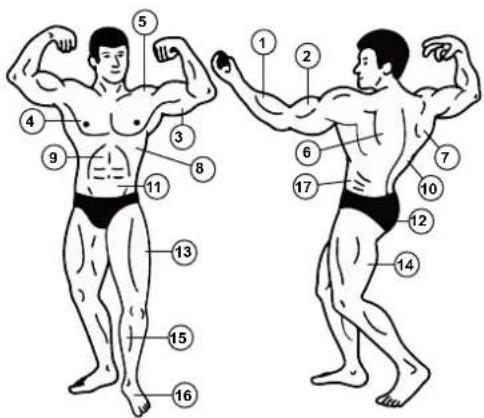
MUSCLES
- Forearm
- Biceps
- Triceps
- Chest
- Deltoid
- Trapezius
- Lower back muscle
- Serratus
- Abdominal
- Latissimus
- Abdominal
- Glutes
- Quadriceps
- Large leg muscle
- Stepper muscle
- Foot extensor muscle
- Oblique muscle
EXERCISES
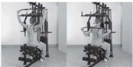
(Pictures show examples of exercise options at another fitness station.)
Exercise 1: Leg extension Exercise 2: Leg curls Exercise 3: Overlay
natural_image
Two-panel black-and-white photo showing a person performing seated exercise on a stationary chair (no text or symbols visible)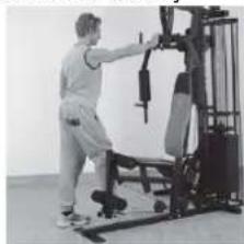
natural_image
Person performing a fitness exercise using a machine tool (no visible text or symbols)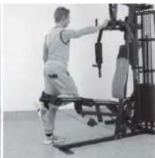
natural_image
Person performing a leg exercise machine on a gym (no visible text or symbols)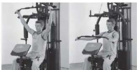
natural_image
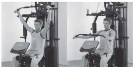
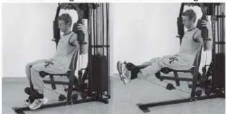
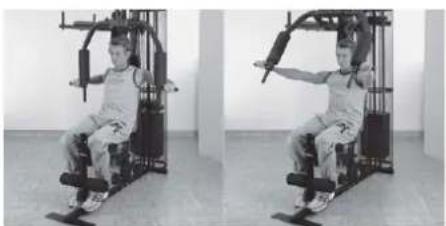
Two-panel black-and-white photo showing a person performing a seated exercise on a fitness machine (no text or symbols visible)Exercise 4: Lat Pulldown

natural_image
Two-panel black-and-white photo showing a person performing a seated exercise on a fitness machine (no text or symbols visible)Exercise 5: Arm curl
natural_image
Two-panel black-and-white photo showing a person performing a seated exercise on a fitness machine (no text or symbols visible)Exercise 6: Front pulling
natural_image
Two-panel black-and-white photo showing a person performing a leg exercise using a weightlifting machine (no text or symbols visible)Exercise 09: ButterflyExercise 7: Bench press Exercise 8:
natural_image
Two-panel black-and-white photo showing a person performing a seated exercise on a fitness machine, no text or symbols visible.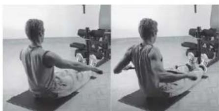
natural_image
Side-by-side black-and-white photo of a person performing a seated exercise on a mat, with exercise equipment in the background (no visible text or symbols)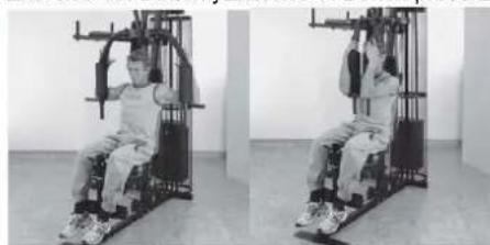
natural_image
Two-panel black-and-white photo showing a person performing a seated exercise on a fitness machine (no text or symbols visible)The complete training instructions with over 45 exercise examples you can found at: www.christopeit-sport.com.
PARTS LIST – SPARE PARTS LIST
Type: SP5000
Order-Nr.: 2281
Date of technical data: 28.04.2024
Dimensions approx: [cm]: L 179 x W 151 x H 197
Space requirements [^2] : 4
Weight approx. [kg]: 140
Load max. (user weight) [kg]: 130
FEATURES NOTE
- Redline Design
- 60Kg weights (12pcs. with 5Kg)
- Bench press
- Leg curls
• Stepper with hydraulic cylinder - Latissimus bar and curl bar
- Bench press and butterfly combinations
• Different rope exercises
• Hand grip and ankle strap - Suitable for weights up to max. 70 kg
• Square - section steel tube 50 x 50 mm
Please contact us if any components are defective or missing, or if you need any spare parts or replacements in future.
This product is created only for private Home sports activity and not allowed to us in a commercial or professional area. Home Sport use class H.
| Illustra-tion no. | Designation | Dimensions in mm | Quantity | Attached to illustration no. | ET number |
| 1 Front foot 1 2 33-9188101-ANT | |||||
| 2 Rear foot 1 1 33-9188102-ANT | |||||
| 3 Tubular guide holder 1 4+5 33-9188103-ANT | |||||
| 4 Support 1 1 2+3 33-9188104-ANT | |||||
| 5 Top cross beam 1 3+7 33-2281-01-ANT | |||||
| 6 Cable pulley holder 2 2 55 33-9188106-ANT | |||||
| 7 Support 2 1 1+5 33-2281-02-ANT | |||||
| 8 Cable pulley holder 1 2 7 33-9188108-ANT | |||||
| 9 Butterfly arm holder | 1 39 33-9188109-ANT | ||||
| 10 Guide bar | 2 2+3 33-9988-08-SI | ||||
| 11 Right butterfly arm | 1 | 9 | 33-9188111-ANT | ||
| 12 Leg curler holder | 1 7 33-9188112-ANT | ||||
| 13 Seat support frame | 1 12 33-9188113-ANT | ||||
| 14 Left butterfly arm | 1 9 33-9188114-ANT | ||||
| 15 Leg curler | 1 12 33-9188115-ANT | ||||
| 16 Arm curl stand | 1 20 33-9188116-ANT | ||||
| 17 Seat padding | 1 13 36-2281-01-BT | ||||
| 18 Round pad holder | 2 | 13+15 | 33-9188117-ANT | ||
| 19 Handgrip 1 | 2 11+14 | 33-9188118-ANT | |||
| 20 Arm curl pad | 1 16 36-2281-04-BT | ||||
| 21 Right pedal | 1 34 33-9188119-ANT | ||||
| 22 Crossbar | 1 2+4 33-9188120-ANT | ||||
| 23 Weight support | 2 10 33-9188121-ANT | ||||
| 24 Left pedal | 1 34 33-9188122-ANT | ||||
| 25 Dipping bar | 1 | 4 33-9188123-ANT | |||
| 26 Cable 1 | 2750mm | 1 | 5+40 | 36-9988-02-BT | |
| 27 Twin cable pulley holder | 1 83 33-9188124-ANT | ||||
| 28 Cable 2 | 1980mm | 1 | 6+53 | 36-9988-03-BT | |
| 29 Cable 3 | 2600mm | 1 | 11+14 | 36-2281-07-BT | |
| 30 Handgrip 2 | 2 25 33-9188125-ANT | ||||
| 31 Cable 4 | 1190mm | 1 | 12+15 | 36-9988-05-BT | |
| 32 L plate | 1 5 33-9188126-ANT | ||||
| 33 Round pipe fitting | 1 50 36-9988-06-BT | ||||
| 34 Shaft 1 | 1 4 36-9588-03-BT | ||||
| 35 Cabel pulley holder incl.hook | 1 | 22+83 | 33-9588-24-VZ | ||
| 36 Latissmus bar | 1 55 33-9188127-ANT | ||||
| 37 Curl bar | 1 55 33-9188128-RT | ||||
| 38 Bench press support | 1 7 33-2281-03-ANT | ||||
| 39 Shaft 2 | 1 9 36-9588-01-BT | ||||
| 40 Weight disc bar | 1 26 33-9188130-ANT | ||||
| 41 Weight casing | 2 42+43 33-9188131-ANT | ||||
| 42 Weight casing support | 2 41 33-9188132-ANT | ||||
| 43 Bending plate | 4 41 33-9188133-ANT | ||||
| 44 Steel bearing | 1 2 15 33-9988-24-SI | ||||
| 45 Butterfly shaft | 2 11+14 33-9988-25-SI | ||||
| 46 Hydraulic cylinder holder | 2 21+24 33-9588-22-VZ | ||||
| 47 Standing plate | 2 1 33-9188134-ANT | ||||
| 48 Adjusting plate | 1 7 33-9188135-ANT | ||||
| 49 Locking pin | 2 11+14 36-9988-07-BT | ||||
| 50 Washer | 29//50 | 1 38 36-9988-08-BT | |||
| 51 Weight selector bar | 1 40 36-9988-09-BT | ||||
| 52 Long safety bracket | 1 15 36-9988-10-BT | ||||
| 53 Chain 1 | 8 Glieder | 1 | 55(+28) | 36-9988-11-BT | |
| 54 Chain 2 | 22 Glieder | 1 | 55(+31) | 36-9788-03-BT | |
| 55 Carbine hook | 5 36+53+54 | 36-9588-35-BT | |||
| 56 Steel bearing | 2 6 4+21+24 | 36-9588-32-BT | |||
| 57 Steel bearing | 3 10 5+9+11+14 | 36-9588-33-BT | |||
| 58 Hydraulic cylinder | 2 22+46 36-9588-08-BT | ||||
| 59 Cable 5 | 560mm | 1 21+24 36-9588-15-BT | |||
| 60 Large back pad | 1 7 | 36-2281-02-BT | |||
| 61 Forearm pad | 2 25 36-2281-05-BT | ||||
| 62 Small back pad | 1 25 36-2281-06-BT | ||||
| 63 Foam rubber roll | 100//300 2 11+14 36-9988-12-BT | ||||
| 64 Foam rubber roll | 100//180 4 18 36-9588-25-BT | ||||
| 65 Head pad | 1 7 36-2281-03-BT | ||||
| 66 First weight | 1 40 36-9988-13-BT | ||||
| 67 Weight plate | 11 | 10 36-9988-14-BT | |||
| 68 Antislip covering left | 1 24 36-9988106-BT | ||||
| 69 Handgrip bolt | 1 | 1 15 36-9988-15-BT | |||
| 70 Handgrip bolt | 2 | 1 9 36-9988-16-BT | |||
| 71 Handle foam | 2 36 36-9988-17-BT | ||||
| 72 V-handle | 1 55+26 36-9988-18-BT | ||||
| 73 Ankle strap | 1 55+31 36-9988-19-BT | ||||
| 74 Lock knob | 1 12 36-9988-20-BT | ||||
| 75 Handgrip nut | 2 46 36-9588-21-BT | ||||
| 76 Handle wrapping | 4 11+14+25+36+37 | 36-9588-19-BT | |||
| 77 Product designation | 1 43 33-2281-05-BT | ||||
| 78 Rubber buffer | 1 | 26//56 | 2 | 10 | 36-9988-30-BT |
| 79 Rubber buffer | 2 | 25x40 | 2 | 11+14 | 36-9988-21-BT |
| 80 Plastic tube sleeve | 1 15 36-9988-22-BT | ||||
| 81 Plastic buffer | 1 | 1 12 36-9588-20-BT | |||
| 82 Plastic buffer | 2 | 2 21+24 36-9588-38-BT | |||
| 83 Cabel pulley | 13 | 5+84 | 36-9588-27-BT | ||
| 84 Cable pulley cover | 24 | 83 36-9588-26-BT | |||
| 85 Square stopper | 50x50 | 7 | 1+2+3+4 | 39-9841 | |
| 86 Square stopper | 25x50x1.5 | 2 13 39-9842 | |||
| 87 Square stopper | 25x50x2 | 2 9 39-9842 | |||
| 88 Square stopper | 45x45 | 1 12 39-9845 | |||
| 89 Square stopper | 38x38 | 2 25 39-9840 | |||
| 90 Round stopper | 50x1.5 | 2 11+14 36-9988-23-BT | |||
| 91 Round stopper | 60x1.5 | 1 15 36-9988-24-BT | |||
| 92 Round stopper | 25x1.5 | 2 11+14 36-9988-25-BT | |||
| 93 Round stopper | 25x2 | 4 18 39-10146 | |||
| 94 Plastic bushing for pulley | 15 | 2 5 36-9588-18-BT | |||
| 95 Plastic bushing for pulley | 20 | 2 15 36-9988-26-BT | |||
| 96 Plastic cap | 1 40 36-9988-27-BT | ||||
| 97 Fillister-head Philips screw | M6x15 | 5 81+82 39-9911 | |||
| 98 Fillister-head Philips screw | 4 | 39-10296-SW | |||
| 99 Round-headed Allen screw M8x15 6 22+34+39 | 39-9888-CR | ||||
| 100 Hexagonal bolt M6x16 17 41+42+43 39-10120 | |||||
| 101 Hexagonal bolt M8x20 4 20+62 | 39-10095-CR | ||||
| 102 Hexagonal bolt M8x30 2 11+14+19 | 39-9906 | ||||
| 103 Hexagonal bolt M8x40 2 46 | 39-9817 | ||||
| 104 Hexagonal bolt M8x45 2 17 | 39-9914 | ||||
| 105 Hexagonal bolt M8x55 4 61 | 39-10056 | ||||
| 106 Hexagonal bolt M8x65 1 5+32 | 39-9814-CR | ||||
| 107 Hexagonal bolt M8x70 4 60+65 | 39-10157 | ||||
| 108 Hexagonal bolt M10x20 | 14 5+7+10+30+45 | 39-9974-CR | |||
| 109 Hexagonal bolt M10x25 | 1 6 | 39-10025-CR | |||
| 110 | Hexagonal bolt | M10x45 | 11 | 1+5+6+8+27+35 | 39-10131-CR |
| 111 | Hexagonal bolt | M10x65 | 2 | 38 | 39-9982-CR |
| 112 | Hexagonal bolt | M10x70 | 15 | 3+4+5+7+12+22 | 39-10148-CR |
| 113 | Hexagonal bolt | M10x75 | 2 | 47 | 39-10186-CR |
| 114 | Hexagonal bolt | M10x80 | 3 | 8+15 | 39-10055-CR |
| 115 | Hexagonal bolt | M10x90 | 1 | 12 | 39-10015 |
| 116 | Washer | 6//12 | 36 | 100 | 39-10007-CR |
| 117 | Washer | 8//16 | 22 | 99+101-107 | 39-9917-CR |
| 118 | Washer | 10//20 | 86 | 108-115 | 39-9989-VC |
| 119 | Washer | 12//24 | 1 40(+26) | 39-9986-CR | |
| 120 | Washer | 10//38 | 5 | 70+75+99 | 39-10249-CR |
| 121 | Washer | 8//28 | 4 | 99 | 39-10180-CR |
| 122 | Spring washer | for M10 | 12 | 108 | 39-9995-CR |
| 123 | Spring washer | for M8 | 18 | 99+101+102+104+105+107 | 39-9864-CR |
| 124 | Self-locking nut | M10 | 36 | 109-115 | 39-9981-CR |
| 125 | Self-locking nut | M8 | 3 | 103+106 | 39-9818-CR |
| 126 | Self-locking nut | M6 | 18 | 100 | 39-9816-VC |
| 127 | Square stopper | 40x80 | 2 | 21+24 | 36-9988111-BT |
| 128 | Antislip covering right | 1 | 21 | 36-9988110-BT | |
| 129 | Washer | 6//18 | 4 | 98 | 39-9993 |
| 130 | Spring washer | for M6 | 4 | 98 | 39-9865-CR |
| 131 Cap | for M10 | 80 | 36-9988108-BT | ||
| 132 Cap | for M8 | 24 | 36-9988109-BT | ||
| 133 | Cap for the handle | 25mm | 10 | 11+14+19+25+36+37 | 36-9988-32-BT |
| 134 Adjusting plate | 1 2 | 33-9988136-ANT | |||
| 135 Hexagonal bolt M6x20 1 32+43 | 39-10128 | ||||
| 136 Bolt | M10x40 | 1 12 | 39-10402 | ||
| 137 Tool Set | 1 | 36-9988-28-BT | |||
| 138 Assembly instructions | 36-2281-08-BT | ||||
NOTES
SommairePage


ÉTAPE 10
ÉTAPE 11
ÉTAPE 12
CONTRÔLE
CONSIGNES GÉNÉRALES DE FORMATION
[Endurance force > Hype trophy
Endurance force > Hypertrophie
Maximale force > Endurance force ]
natural_image
Two-panel black-and-white photo showing a person performing seated exercise on a stationary platform (no text or symbols visible)natural_image
Two-panel black-and-white photo showing a person performing a seated exercise machine (no text or symbols visible)natural_image
Two-panel black-and-white photo showing a person performing seated exercise on a gym machine (no text or symbols visible)Exercice 6 : Tirage frontale
natural_image
Two-panel black-and-white photo showing a person performing a seated exercise on a machine, no visible text or symbols.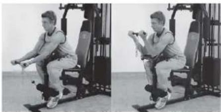
natural_image
Two-panel black-and-white photo showing a person performing a seated exercise on a fitness machine (no text or symbols visible)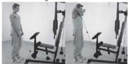
natural_image
Two-panel black-and-white photo showing a person performing a resistance exercise using a leg presser machine (no text or symbols visible)natural_image
Two-panel black-and-white photo showing a person performing a seated leg exercise on a fitness machine, no text or symbols visible.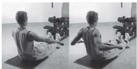
natural_image
Side-by-side black-and-white photo of a person performing seated yoga on a mat, with exercise equipment in the background (no visible text or symbols)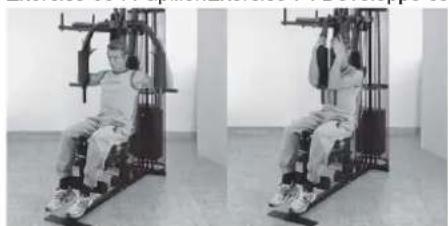
natural_image
Two-panel black-and-white photo showing a person performing seated exercise on a stationary platform (no text or symbols visible)
STAP 4

STAP 7

STAP 10
STAP 11
STAP 12
STAP 13

CONTROLE
ALGEMENE TRAININGSINSTRUCTIES
Competitie - Zone: Prestaties / Competitie Training
02: Training hartslagberekening
natural_image
Sequence of four sequential illustrations showing a person performing a stretching or kneeling movement (no text or symbols)OPDRACHTEN
natural_image
Two-panel black-and-white photo showing a person performing seated exercise on a stationary platform (no text or symbols visible)natural_image
Two-panel black-and-white photo showing a person performing a Pilates exercise machine (no text or symbols visible)Oefening 5: Arm krullen
natural_image
Two-panel black-and-white photo showing a person performing a seated exercise on a gym machine, no visible text or symbols.natural_image
Two-panel black-and-white photo showing a person performing a seated exercise using a leg presser machine (no text or symbols visible)
natural_image
Two-panel black-and-white photo showing a person performing a seated exercise using a weightlifting machine (no text or symbols visible)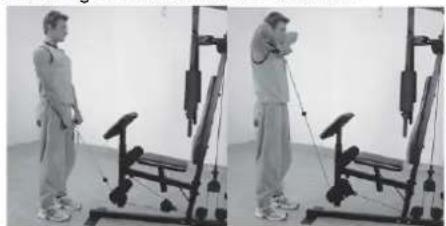
natural_image
Two-panel black-and-white photo showing a person performing a resistance band exercise using a leg presser machine (no text or symbols visible)natural_image
Two-panel photo showing a person performing a seated exercise on a stationary chair (no text or symbols visible)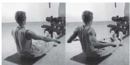
natural_image
Side-by-side black-and-white photo showing a person performing a seated core exercise on a mat, with exercise equipment in the background (no visible text or symbols)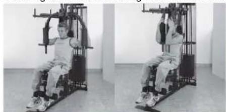
natural_image
Two-panel black-and-white photo showing a person seated on a fitness machine, no visible text or symbols
KROK 4
KROK 5
KROK 6
KROK 7
KROK 10
KROK 11
KROK 12
KROK 13

SPRAWDZENIE
natural_image
Sequence of four sequential illustrations showing a person performing a stretching or kneeling movement (no text or symbols)ĆWICZENIA
natural_image
Two-panel black-and-white photo showing a person performing seated exercise on a stationary platform (no text or symbols visible)natural_image
Two-panel photo showing a person performing a seated exercise on a fitness machine, no text or symbols visiblenatural_image
Two-panel photo showing a person performing a seated exercise on a stationary chair (no text or symbols visible)natural_image
Two-panel black-and-white photo showing a person performing a resistance exercise using a machine (no text or symbols visible)natural_image
Two-panel black-and-white photo showing a person performing a seated exercise on a stationary platform (no text or symbols visible)natural_image
Side-by-side black-and-white photo of a person performing seated exercise on a mat, with exercise equipment in background (no visible text or symbols)natural_image
Two-panel black-and-white photo showing a person performing a seated exercise on a gym machine (no text or symbols visible)natural_image
Two-panel black-and-white photo showing a person performing a leg exercise using a stationary exercise machine (no text or symbols visible)Ćwiczenia 9: Motyl
natural_image
Two-panel black-and-white photo showing a person using a leg lift machine in a gym (no text or symbols visible)
© by Top-Sports Gilles GmbH D-42551 Velbert (Germany)