EBH 801 - Hammer EINHELL - Free user manual and instructions
Find the device manual for free EBH 801 EINHELL in PDF.


| Product type | Electric rotary hammer |
| Brand | Einhell |
| Model | EBH 801 |
| Supply voltage | 230 V ~ 50 Hz (compatible 220 V/50 Hz) |
| Impact energy | 4.3 J (per blow) |
| Sound pressure level | 98 dB(A) |
| Sound power level | 108.6 dB(A) (LWA) |
| Vibration (hand-arm) | 4 m/s² (ahw) |
| Weight | 5.9 kg |
| Tool connection | Large splined shaft |
| Max drilling diameter | 25 mm (in masonry) |
| Impact mechanism | Electromagnetic induction (starts under pressure) |
| Functions | Drilling, hammer drilling, chiseling |
| Supplied accessories | Auxiliary handle, dust cap, chisels/drill bits |
| Maintenance | Cleaning ventilation slots, checking carbon brushes |
| Safety | Wear safety glasses, ear protection, dust mask |
| Warranty | 12 months |
| Spare parts | Available via after-sales service |
Frequently Asked Questions - EBH 801 EINHELL
User questions about EBH 801 EINHELL
0 question about this device. Answer the ones you know or ask your own.
Ask a new question about this device
Download the instructions for your Hammer in PDF format for free! Find your manual EBH 801 - EINHELL and take your electronic device back in hand. On this page are published all the documents necessary for the use of your device. EBH 801 by EINHELL.
USER MANUAL EBH 801 EINHELL
EBH 801
Standard

Gehörschutz tragen!
Wear ear-muffs
Porter un casque anti-bruit
| ●Power per blow: 4.3 J (Joule) | |
| ●Chuck type: Large spline shaft | |
| ●Weight: | 5.9 |
| ●Sound pressure level: 98 dB(A) | |
| ●Sound power level: 108.6 dB(A) LWA | |
| ●Vibration aw | 4 m/s 2 |
| ●Radio suppressed in conformance with EC Guideline 89/336/EEC | |
Before you use the hammer drill
Check that the voltage of your power source is the same as that marked on your hammer drill's rating plate. Hammer drills marked with 230 V 50 Hz can also be operated from a 220 V 50 Hz supply.
General information
The electric hammer drill you have purchased is designed for use in areas lying beyond the performance limits of a standard hammer drill. An ergonomically shaped handle enables safe and tireless working.
Masonry and
concrete ceilings
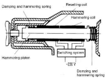
pose no problem for this Einhell hammer drill thanks to its newly developed Inductive hammer action (electromagnetic principle). Special features of this innovative machine are its compact design and extremely rugged interior workings. Optimum power transmission is guaranteed by the large spline shaft.
Thanks to its large range of special accessories the hammer drill can be put to universal use.
●Cutting holes through masonry with the selection of chisel bits supplied
●Drilling holes of all types up to a maximum diameter of 25 mm
●Cutting channels in masonry in preparation for laying cables
Important!
The inductive hammer function is not triggered until the tool comes up against a counter pressure. For the hammer action to start, you must first press the hammer drill with a chisel bit or drill bit against the masonry, concrete ceiling, etc.
Safety regulations
Important! To protect yourself from the risk of electric shock, injury and fire when using an electric tool, it is imperative to take the following basic safety precautions. Read and note these instructions before you use the machine:
- Check the voltage (volt) marked on the rating plate.
- When using cable drums, run all the cable off the drum. Minimum conductor cross section: 1.0 mm 2 .
- When using the electric hammer drill outdoors, connect to the power supply with a type H07RN-F 3G 1.5 mm 2 extension cable and rain-water-
●Make sure of your footing on ladders and scaffolding when drilling free-handed. - Use a line detector to localize lines in walls with concealed electric, water or gas lines. Avoid touching live components or conductors.
●Wear ear muffs to protect your hearing. Loss of hearing can be a gradual process!
●Wear goggles and use a dust mask on jobs generating dust. - Do not use in areas where there are vapours or flammable liquids.
●Always pull the plug out of the socket before cleaning or making changes to the machine. - Protect the power cable from damage. Oil and acid can damage the cable.
●Never overload the machine.
●Secure all workpieces sufficiently.
●Important! It is Imperative to follow all national safety regulations concerning installation, operation and maintenance.
●Wear ear muffs to protect your hearing. Loss of hearing can be a gradual process!
●Wear goggles and use a dust mask on jobs generating dust.
GB
●Do not use in areas where there are vapours or flammable liquids.
●Always pull the plug out of the socket before cleaning or making changes to the machine
●Chisel bits and drill bits may be flung out of the machine accidentally and cause serious injury:
●Before starting to work, always check that the chisel or drill bit is properly locked in the chuck.
●Examine the chuck regularly for signs of wear or damage.
●Never start up a hammer tool until it pressed against a workpiece (wall, ceiling, etc.).
- When you are finished, unplug the hammer drill from the electric supply and remove the chisel or drill bit from the machine.
●Always disconnect the hammer drill from the electric supply before you change a chisel or drill bit.
- Protect your eyes and other workers from flying particles and splinters. Wear a helmet! Set up partition walls!
●Wear work gloves to protect fingers from bruising and grazing.
●Vibrations can injure the hand-arm system. Keep exposure to vibrations as short as possible.
Maintenance
- Keep your machine clean at all times.
●Never use caustic agents to clean the plastic parts. - At the end of your work, to prevent dust deposits you should use compressed air (max. 3 bar) to clean out the ventilation slots with the motor running.
- Check the carbon brushes regularly (dirty or worn carbon brushes result in excessive sparking and speed faults).
- If you discover any damage, use the enclosed drawing and parts list to establish exactly which spare parts are required and order them from our Customer Service.
Functional principle behind the electromagnetic hammer drill
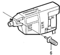
Fitting the handle
You can screw the handle (6) in its mounting thread on either the left or right-hand side of the machine.
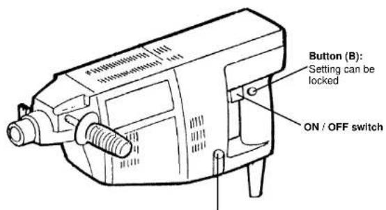
Switching on: Press operating switch A
Continuous duty: Lock switch A with locking
button B
Switching off: Press operating switch A and
let go
Selector button (7)
Drill - hammer
Hammer ON/OFF
The hammer action can be switched on and off by pressing the button (7).
Important! Wait until the machine stops before you change over.
View of the hammer drill from the back
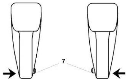
Hammer ON Drilling with hammer action
10
GB
Inserting the tool: (Fig. A)
- Caution! Pull out the power plug.
- Push up the locking lever (4).
- Insert the tool as far as the stop, turning it at the same time if necessary.
●Push the locking lever back down 180°.
●Pull on the tool to check that it is locked
●Tool change: Push up the locking lever and remove the tool.
Important!
●Before you insert the tool, clean away any dust etc. from the tool chuck (5) and the tool shaft.
- Use the dust cap to protect the drill and chisel chuck (5).
●Always use the additional handle when drilling.
Locking lever (4)
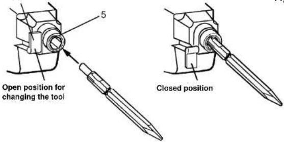
Fig. A
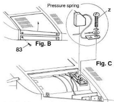
Cleaning and replacing the carbon brushes (see numbers in the parts list):
●Caution! Pull out the power plug.
●Undo the 4 screws (83) and remove the two covers (23, 32) by lifting slightly with a screw-driver (Fig. B).
●Lift the compression spring (25) with a screw-driver and take out the carbon brush (24).
●Use compressed air (max. 3 bar) to clean the carbon brushes (24) and holder (31).
●Changing the carbon brushes (see Fig. C): Undo the cheese-head screw (z) and remove the terminal wire of the worn carbon brush.
● Fix the terminal of the new carbon brush with the cheese-head screw (z).
●Lift the compression spring (25) again to insert the carbon brush. Make sure the compression spring sits correctly (it should press inside the notch in the carbon brush).
●Replace the covers (23, 32) and fasten with the 4 screws (83).
F
Description
1 Bouton de blocage
52
The guarantee period begins on the sales date and is valid for 1 year.
Responsibility is assumed for faulty construction or material or functional defects.
Any necessary replacement parts an necessary repair work are free of charge.
We do not assume responsibility for consequential damage.
Your customer service partner
© GARANTIE EINHELL
⑤ EINHELL GARANTIBEVIS
EINHELL GARANTIBEVIS
15 Warwick House Ind. Park, Banbury Road,
Sautham, Warwickshire CV 33 OPS
Technical changes subject to change

- BEFORE YOU USE THE HAMMER DRILL
- GENERAL INFORMATION
- MASONRY AND
- IMPORTANT
- SAFETY REGULATIONS
- GB
- MAINTENANCE
- FITTING THE HANDLE
- HAMMER ON/OFF
- INSERTING THE TOOL: (FIG. A)
- CLEANING AND REPLACING THE CARBON BRUSHES (SEE NUMBERS IN THE PARTS LIST)
- F
- DESCRIPTION
- © GARANTIE EINHELL
- ⑤ EINHELL GARANTIBEVIS
- EINHELL GARANTIBEVIS
Brand : EINHELL
Model : EBH 801
Category : Hammer