I 23-1 ER - Cooker DELONGHI - Free user manual and instructions
Find the device manual for free I 23-1 ER DELONGHI in PDF.

User questions about I 23-1 ER DELONGHI
0 question about this device. Answer the ones you know or ask your own.
Ask a new question about this device
Download the instructions for your Cooker in PDF format for free! Find your manual I 23-1 ER - DELONGHI and take your electronic device back in hand. On this page are published all the documents necessary for the use of your device. I 23-1 ER by DELONGHI.
USER MANUAL I 23-1 ER DELONGHI
natural_image
Simple line drawing of a circular object with internal vertical lines and two droplet symbols below (no text or labels)Fig. 2.1a

natural_image
Symbolic diagram with a circle containing vertical lines and droplets, no text or labels present.Fig. 2.1b

Fig. 2.2

natural_image
Simple line drawing of a hat with arrows indicating motion or change, no text or symbols presentFig. 2.3
BRUCIATORI A GAS
natural_image
Three line drawings of cooking pots with crossed-out handles, no text or symbols present
natural_image
Three diagrams showing different types of heating or filtration setups with no text or symbolsFig. 3.3
natural_image
Circular maze pattern with concentric rings and a central loop, labeled '4.3' at bottom left (no text or symbols within the maze itself)Fig. 4.3
natural_image
Circular diagram with concentric wavy lines and a diagonal line crossing through it, no text or symbols present.Fig. 4.4
natural_image
Simple diagram of two vertical bars inside a circle, no text or symbols presentFig. 4.5
bar_stacked
| Zona comandata da commutatore | 0 - 6 | 1 | 2 | 3 | 4 | 5 | 6 | 7 | 8 | 9 | 10 | 11 | 12 | | --- | --- | --- | --- | --- | --- | --- | --- | --- | --- | --- | --- | --- | --- | | Riscaldamento | 0 | 0 | 0 | 0 | 0 | 0 | 0 | 0 | 0 | 0 | 0 | 0 | 0 | | Cottura | 0 | 0 | 0 | 0 | 0 | 0 | 0 | 0 | 0 | 0 | 0 | 0 | 0 | | Arrostire-Friggere | 0 | 0 | 0 | 0 | 0 | 0 | 0 | 0 | 0 | 0 | 0 | 0 | 0 |natural_image
Hand using a tool to brush or mark on a circular object, labeled 'Fig. 5.1' (no other text or symbols)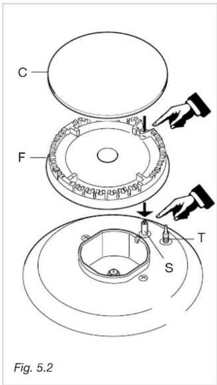
text_image
C F T S Fig. 5.2BRUCIATORI E GRIGLIE
natural_image
Mechanical assembly diagram showing a rotating component with a curved arrow indicating motion (no text or symbols)BRUCIATORE A TRIPLA CORONA
natural_image
Line drawing of a wrench gripping a mechanical component (no text or symbols)| IT TABELLA INIETTORI - Piani senza valvolatura | ||||
| Cat: II 2H3+ | PORTATA MAX | PORTATA MIN | G30/G3128-30/37 mbar | G2020 mbar |
| BRUCIATORI | [Hs - kW] | [Hs - kW] | ∅ iniettore[1/100 mm] | ∅ iniettore[1/100 mm] |
| Semirapido (SR) 1,75 0,45 | 65 | 97 | ||
| Rapido (R) | 3,00 0,75 | 85 | 115 | |
| Tripla corona | 3,50 | 1,50 | 95 | 135 |
| IT TABELLA INIETTORI - Piani con valvolatura | |||||
| Cat: III 1a2H3+ | PORTATA MAX | PORTATA MIN | G30/G3128-30/37 mbar | G2020 mbar | G1108 mbar |
| BRUCIATORI | [Hs - kW] | [Hs - kW] | ∅ iniettore[1/100 mm] | ∅ iniettore[1/100 mm] | ∅ iniettore[1/100 mm] |
| Semirapido (SR) 1,75 0,45 65 97 190 | |||||
| Rapido (R) 3,00 0,75 85 115 300 | |||||
| Tripla corona 3,50 1,50 95 135 340 | |||||
text_image
J Fig. 7.3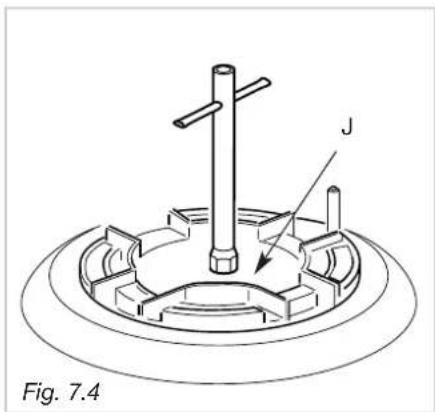
text_image
Fig. 7.4natural_image
Technical line drawing of a screwdriver with a base mount, labeled Fig. 7.5 (no text or symbols on the diagram itself)
text_image
Fig. 7.6 Anatural_image
Technical line drawing of an open electrical connector with labeled component 'F' (no text or symbols beyond label)
text_image
230 V ~ L1 (L)2 N PE Fig. 8.3
text_image
230 V ~ L N Fig. 8.4RIPARAZIONI
Thank you for having purchased and given your preference to our product.
The safety precautions and recommendations reported below are for your own safety and that of others. They will also provide a means by which to make full use of the features offered by your appliance.
Please preserve this booklet carefully. It may be useful in future, either to yourself or to others in the event that doubts should arise relating to its operation.
This appliance must be used only for the task it has explicitly been designed for, that is for cooking foodstuffs. Any other form of usage is to be considered as inappropriate and therefore dangerous.
The manufacturer declines all responsibility in the event of damage caused by improper, incorrect or illogical use of the appliance.
IMPORTANT PRECAUTIONS AND RECOMMENDATIONS
√ After having unpacked the appliance, check to ensure that it is not damaged.
If you have any doubts, do not use it and consult your supplier or a professionally qualified technician.
√ Packing elements (i.e. plastic bags, polystyrene foam, nails, packing straps, etc.) should not be left around within easy reach of children, as these may cause serious injuries.
√ The packaging material is recyclable and is marked with the recycling symbol ⬆.
√ Do not attempt to modify the technical characteristics of the appliance as this may become dangerous to use.
√ The manufacturer cannot be considered responsible for damage caused by unreasonable, incorrect or rash use of the appliance.
√ If you should decide not to use this appliance any longer (or decide to substitute an older model), before disposing of it, it is recommended that it be made inoperative in an appropriate manner in accordance to health and environmental protection regulations, ensuring in particular that all potentially hazardous parts be made harmless, especially in relation to children who could play with old appliances.
√ The appliance should be installed and all the gas/electrical connections made by a qualified engineer in compliance with local regulations in force and following the manufacturer's instructions
IMPORTANT PRECAUTIONS AND RECOMMENDATIONS FOR USE OF ELECTRICAL APPLIANCES
Use of any electrical appliance implies the necessity to follow a series of fundamental rules. In particular:
√ Never touch the appliance with wet hands or feet;
√ do not operate the appliance barefooted;
√ do not allow children or disabled people to use the appliance without your supervision.
The manufacturer cannot be held responsible for any damages caused by improper, incorrect or unreasonable use of the appliance.
TIPS FOR THE USER
√ During and after use of the cooktop, certain parts will become very hot. Do not touch hot parts.
√ Keep children away from the cooking hob when it is in use.
√ After use, ensure that the knobs are in position • (off), and close the main gas delivery valve or the gas cylinder valve.
√ In case of difficulty in the gas taps operation, call Service.
√ Before any cleaning or maintenance, switch off the electricity to the cooktop.
Risk of fire!
√ Do not leave inflammable material on the cooktop.
√ Make sure that the electrical cables of other appliances installed nearby cannot come into contact with the cooktop.
√ Never cook the food directly on the electric hotplates, but in special pans or containers.
GUARANTEE
Your new appliance is covered by guarantee. You will find the certificate of guarantee enclosed together with these documents; if it is missing, you must ask your supplier for a copy, indicating the date of purchase and the serial number that is stamped on the identification plate of the product.
In order to validate your guarantee you must retain the receipt of purchase from your supplier together with the certificate.
In case of necessity, these documents will have to be shown to the qualified service technicians.
In the event that the above-described procedure is not properly fulfilled, the technical staff will be forced to charge you all expenses for any repair work to the product.
All service maintenance operations must be carried out by authorised service centres, using only original spare parts.
The service centre closest to you can be found on the enclosed "SERVICE CENTRES" list.
DECLARATION OF CE CONFORMITY
- This cooking hob has been designed to be used only for cooking. Any other use (such as heating a room) is improper and dangerous.
- This cooking hob has been designed, constructed, and marketed in compliance with:
-Safety requirements of the "Gas" Directive 90/396/EEC;
-Safety requirements of "Low voltage" Directive 2006/95/EC;
-Safety requirements of "EMC" Directive 89/336/EEC;
-Requirements of Directive 93/68/EEC.
CE
These instructions are only valid for the countries indicated by the symbols on the cover of the instruction booklet and on the appliance itself.
Fig. 1.1
text_image
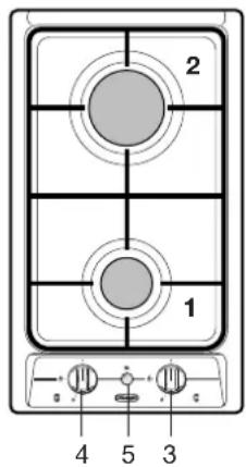
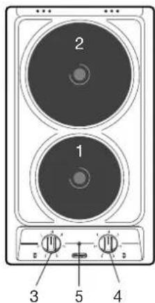
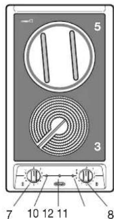
2 1 4 5 3"2 GAS" COOKING HOB (Fig. 1.1)
The appliance has class 3
COOKING POINTS
- Semirapid burner (SR) - 1,75 kW
- Rapid burner (R) - 3,00 kW
CONTROL PANEL DESCRIPTION
- Burner 2 (R) control knob
- Burner 1 (SR) control knob
- Electric gas-lighting device;
if the device is not installed, the appliance may be provided with:
- A gas-lighter incorporated into the knob (★ symbol beside flame ⚠ - max. heat/max. gas flow).
- No gas-lighter (no ★ symbol beside knobs).
√ If the appliance has a safety valve system fitted (beside every burner is a T-shaped probe, as in Fig. 5.2 - not to be confused with the S-shaped electrode of the gas-lighter), the flow of gas will be stopped if and when the flame should accidentally go out.
text_image
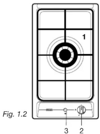
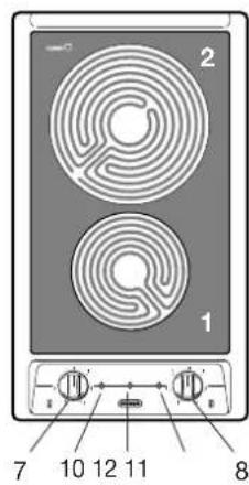
1 Fig. 1.2 3 2"1 GAS triple ring burner" COOKING HOB (Fig. 1.2)
The appliance has class 3
COOKING POINTS
- Triple ring burner - 3,50 kW
CONTROL PANEL DESCRIPTION
- Triple ring burner control knob
- Electric gas-lighting device;
if the device is not installed, the appliance may be provided with:
- A gas-lighter incorporated into the knob (★ symbol beside flame ⬆ - max. heat/max. gas flow).
- No gas-lighter (no ★ symbol beside knobs).
Important Note:
√ If the appliance has a safety valve system fitted (beside every burner is a T-shaped probe, as in Fig. 5.2 - not to be confused with the S-shaped electrode of the gas-lighter), the flow of gas will be stopped if and when the flame should accidentally go out.
CAUTION:
If the burner is accidentally extinguished, turn the gas off at the control knob and wait at least 1 minute before attempting to relight.
CAUTION:
Gas hobs produce heat and humidity in the environment in which they are installed.
Ensure that the cooking area is well ventilated by opening the natural ventilation grilles or by installing an extractor hood connected to an outlet duct.
CAUTION:
If the hob is used for a prolonged time it may be necessary to provide further ventilation by opening a window or by increasing the suction power of the extractor hood (if fitted).
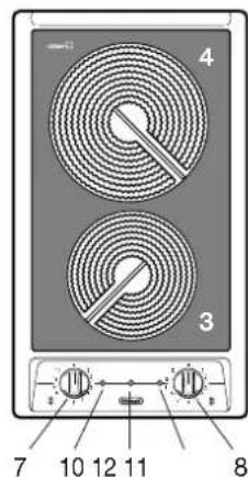
"2 ELECTRIC" COOKING HOB (Fig. 1.3)
- Electrical isolation Class I.
- Overheating surfaces protection Type Y.
COOKING POINTS
- Electrical plate ∅ 145 - (1000 W - 1500 W)
- Electrical plate ∅ 180 - (1500 W - 2000 W)
CONTROL PANEL DESCRIPTION
- Electrical plate 1 control knob
- Electrical plate 2 control knob
- Power indicator light
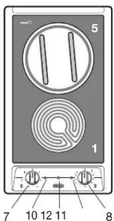
VITROCERAMIC HOBS (Fig. 1.4, 1.5, 1.6, 1.7)
- Electrical isolation Class I.
- Overheating surfaces protection Type Y.
COOKING POINTS
- 3 circuits cooking zone ∅ 145 - 1200 W
- 3 circuits cooking zone ∅ 180 - 1700 W
- Hi-light cooking zone ∅ 145 - 1200 W
- Hi-light cooking zone ∅ 180 - 1800 W
- Halogen cooking zone ∅ 180 - 1800 W
CONTROL PANEL DESCRIPTION
- Front zone control knob
- Rear zone control knob
- Front zone residual heat indicator
- Rear zone residual heat indicator
- Power indicator light
text_image
2 1 3 5 4Fig. 1.3
text_image
2 1 7 10 12 11 8Fig. 1.4
text_image
4 3 7 10 12 11 8Fig. 1.5
text_image
5 1 7 10 12 11 8Fig. 1.6
text_image
5 3 7 10 12 11 8Fig. 1.7
natural_image
Simple line drawing of a circular object with internal vertical lines and two droplet symbols below (no text or labels)Fig. 2.1a

natural_image
Symbolic diagram with a circle containing vertical lines and droplets, no readable text or labelsFig. 2.1b
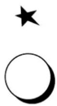
Fig. 2.2

natural_image
Simple line drawing of a hat with arrows indicating motion or change, no text or symbols presentFig. 2.3
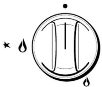
GAS BURNERS
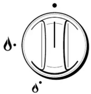
Gas flow to the burners is adjusted by turning the knobs (illustrated in figs. 2.1a - 2.1b) which control the safety valves.
Turning the knob so that the indicator line points to the symbols printed on the panel achieves the following functions:
√ full circle ● = closed valve
√ symbol = maximum aperture or flow
√ symbol = minimum aperture or flow
Tolight one of the gas burners, hold a flame (e.g. a match) close to the top part of the burner, push in and turn the relative knob in an anti-clockwise direction, pointing the knob indicator towards the large flame symbol (i.e. max. gas flow).
Toreduce the gas flow to minimum, rotate the knob further anti-clockwise to point the indicator towards the small flame symbol.
The maximum aperture position permits rapid boiling of liquids, whereas the minimum aperture position allows slower warming of food or maintaining boiling conditions of liquids.
Other intermediate operating adjustments can be achieved by positioning the indicator between the maximum and minimum aperture positions, and never between the maximum aperture and closed positions.
N.B. When the cooker top is not being used, set the gas knobs to their closed positions and also close the cock valve on the gas bottle or the main gas supply line.
VALVELESS ELECTRIC SPARK-LIGHTING GAS BURNERS
Models fitted with electric spark lighter button
On these cooker tops, to light one of the burners you have to push in and turn the relative knob to the maximum aperture position (large flame symbol) and press the electric lighter button (fig. 2.2) until the flame has been lit.
Adjust the gas valve to the desired position.
Models fitted with electric lighter incorporated into the burner knobs
★ symbol beside the ⚠ symbol (max. heat/max. gas flow) (fig. 2.1b).
To light one of the gas burners, push in and turn the relative knob to the maximum aperture position (large flame symbol) and hold the knob in until the flame has been lit. The sparks produced by the lighter situated inside the relative burner will light the flame.
In the event that the local gas supply conditions makes it difficult to light the burner in maximum aperture position, try again with the knob in minimum position.
LIGHTING GAS BURNERS FITTED WITH SAFETY VALVE DEVICE
In order to light the burner, you must:
1 - Turn the knob in an anti-clockwise direction up to the maximum aperture, push in and hold the knob;
In models with the gas lighter incorporated in the knob, this will light the gas. If there is no mains electrical supply, bring a lighted match close to the burner.
2 - For models with push-button lighting only: push the gas-lighter button.
3 – Wait about ten seconds after the gaslights before releasing the knob (starting time for the valve).
4 - Adjust the gas valve to the desired position.
If the burner flame should go out for some reason, the safety valve will automatically stop the gas flow.
To re-light the burner, return the knob to the closed ● position and repeat the operations for lighting.
CHOICE OF BURNER (fig. 2.4)
The symbols printed on the panel beside the gas knobs indicate the correspondence between the knob and the burner.
The most suitable burner is to be chosen according to the diameter and volume capacity of the container to be warmed.
It is important that the diameter of the pots or pans suitably match the heating potential of the burners in order not to jeopardise the efficiency of the burners, bringing about a waste of gas fuel.
A small diameter pot or pan placed on a large burner does not necessarily mean that boiling conditions are reached quicker.
Caution!
the cooking hob becomes very hot during operation.
Keep children well out of reach.
GRATE FOR SMALL PANS
Supplied together with the appliance (See fig. 2.5).
This grate is to be placed on top of the (smaller) semirapid burner when using small diameter pans, in order to prevent them from tipping over.
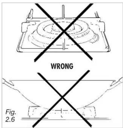
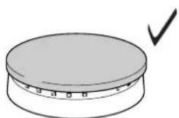
SPECIAL WOK GRILLE (fig. 2.6 e 2.7).
This special grille for woks should be placed over the pan-rest for the largest burner.
Warning:
√ Using woks without this special grille may cause the burner to malfunction.
√ Do not use the grille for ordinary, flat-bottomed saucepans.
DIAMETERS OF PANS WHICH MAY BE USED
ON THE HOBS
BURNERS MINIMUM MAX.
Semirapid 12 cm 22 cm
Rapid 22 cm 26 cm
Triple ring 24 cm 28 cm
Maximum diameter for woks: 36 cm.
do not use pans with concave or convexe bases
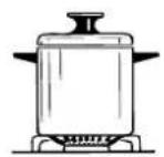
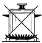
Fig. 2.4
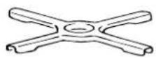
Fig. 2.5
text_image
WRONG Fig. 2.6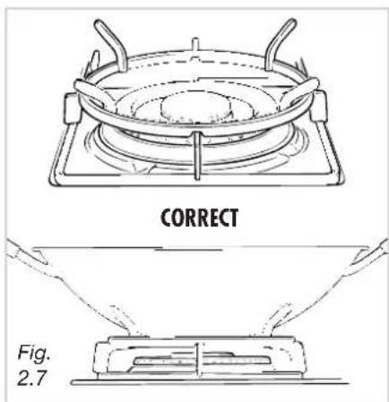
text_image
CORRECT Fig. 2.7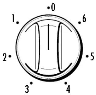
text_image
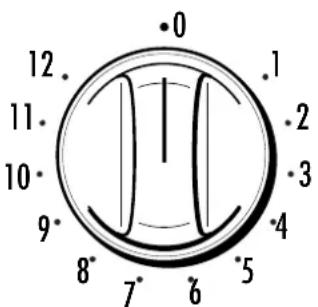
1. 2. 3. 4 5 6 0Fig. 3.1

text_image
0 12. 11. 10. 9. 8. 7. 6 5 4 3 2 1 .1Fig. 3.2
bar_stacked
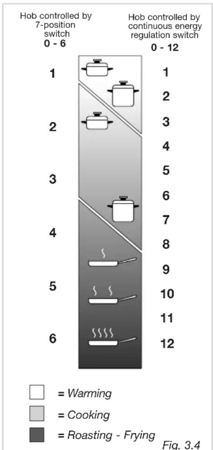
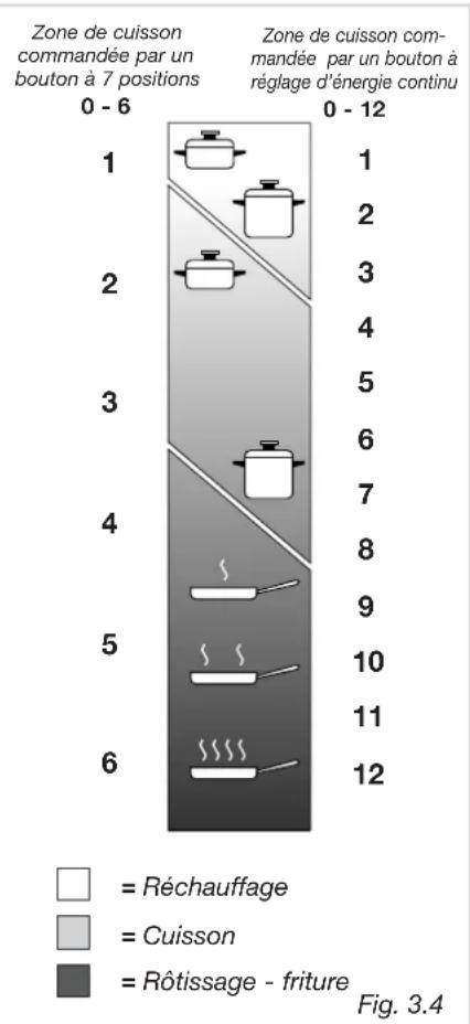
| Position | Warming | Cooking | Roasting - Frying | | :--- | :--- | :--- | :--- | | 1 | 0 | 0 | 0 | | 2 | 0 | 0 | 0 | | 3 | 0 | 0 | 0 | | 4 | 0 | 0 | 0 | | 5 | 0 | 0 | 0 | | 6 | 0 | 0 | 0 | | 7 | 0 | 0 | 0 | | 8 | 0 | 0 | 0 | | 9 | 0 | 0 | 0 | | 10 | 0 | 0 | 0 | | 11 | 0 | 0 | 0 | | 12 | 0 | 0 | 0 | Hob controlled by 7-position switch; Hob controlled by continuous energy regulation switch; Warming; Cooking; Roasting - Frying; Fig. 3.4NORMAL HOTPLATE
To turn on the electric hotplate, rotate the knob (fig. 3.1 - 3.2) o the desired setting. The numbers from 1 to 6 or 1 to 12 indicate the operating positions with increasing number corresponding to higher temperature settings When the pan comes to the boil, turn the heat down to the level desired.
Remember that the hotplate will continue to produce heat for about five minutes after it has been turned off.
RAPID HOTPLATE (red dot)
The rapid hotplate control knob is similar to that of the normal hotplate, with 6 or 12 selectable heating positions (fig. 3.1 - 3.2).
The characteristics of this hotplate, which is also equipped with a thermostatic cut-off device, make it possible to:
- achieve the cooking temperature rapidly
- make full use of its output power using flat-bottomed pans
- limit the output power with unsuitable saucepans.
Never cook food directly on the electric hotplates! Always use a saucepan or special container.
Caution! the cooking hob becomes very hot during operation. Keep children well out of reach.
PROPER USE OF THE ELECTRIC HOTPLATE (fig. 3.3)
When the pan comes to the boil, turn the heat down to the level desired.
Remember that the hotplate will continue to produce heat for about five minutes after it has been turned off.
While using the electric hotplate, you must:
ELECTRIC HOTPLATE USAGE TABLE
| Position of switch | Type of cooking | |
| 0 | 0 | Switched OFF |
| 12 | 12 | For melting operations (of butter or chocolate) |
| 2 | 234 | To keep foods warm or heat small quantities of water. |
| 3 | 456 | To heat greater quantities of water and to whip creams and sauces. |
| 34 | 67 | Slow boiling, e.g. spaghetti, soups, boiled meats, to continue steam heating of roast meats and stews. |
| 4 | 78 | For all kinds of fried foods, steaks, cutlets and cooking without a lid. |
| 45 | 8910 | For browning of meat, cooked potatoes, fried fish and for boiling large quantities of water. |
| 6 | 1112 | Rapid frying, grilled steaks, |
√ avoid keeping it on without something on it;
√ avoid pouring liquids on it while it is hot;
√ use flat-bottomed (electric hotplate type) pots and pans only
√ use cooking receptacles which cover as much of the surface of the hotplate as possible.
√ to save electricity, use lids whenever possible.
√ never cook food directly on the hotplate: always use a pan or suitable container.
An indicator light located close to the control panel signals that the hotplate is operating
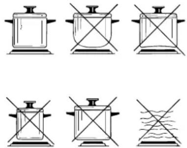
Fig. 3.3
The main characteristic of this pyroceram cooker top is that it permits rapid vertical transmission of the heat from the heating elements below to the saucepans on top.
The heat does not spread horizontally, however, and therefore the glass stays cold only a few centimetres from the hob.
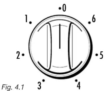
The hobs are controlled by the 7 positions switch (0÷6) (fig. 4.1) or by the continuous energy regulation switch (0÷12) (fig. 4.2).
The heat intensity can be regulated continuously from 0 (off) to "6" or "12" (max).
Check that the hob is clean and then switch on by turning the control knob
When the top is working, the pilot light will be on.
When the hob temperature is above 60^ C, the corresponding indicator light will come on to indicate that the hob is hot.
This light will stay on even after the hob has been switched off to indicate that the hob is still hot.
The residual heat persists for some time after the hob has been switched off.
During this time avoid touching the hob and take particular care if there are children nearby.
The light will go out automatically when the hob temperature drops below 60^ C.
text_image
0 1. 6 2. 5 3. 4 Fig. 4.1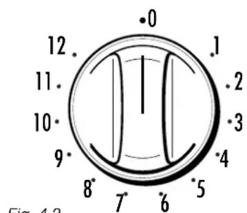
text_image
12 11 10 9 8 7 6 5 4 3 2 1 0 Fig. 4.3Fig. 4.2
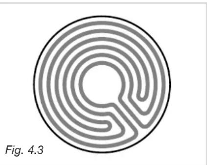
TYPES OF COOKING AREA
"3 circuiti" radiant zones (Fig. 4.3)
The heating element consists of 3 electrical resistances which can operate together or separately according to the setting of the 7-position switch or energy regulator 0-12. It reaches the required temperature very quickly.
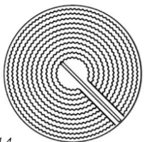
"Hi-light" radiant zones (Fig. 4.4)
The heating element is formed of a coil of resistant material which reaches the working temperature quickly.
Operation of the cooking zone is controlled by a continuous energy regulator from 1 (minimum position) to 12 (maximum temperature).
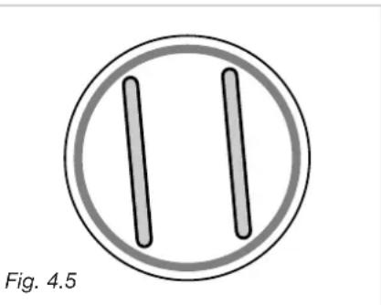
Halogen zones (Fig. 4.5)
The heating element consists of 2 halogen lamps and an electrical resistance.
It instantly reaches the required temperature.
The area is controlled by a continuous energy regulator from 1 (minimum position) to 12 (maximum temperature).
Warning for eyes: Do not stare at the lamp when it is on.
natural_image
Circular maze pattern with concentric rings and a central loop, labeled 'Fig. 4.3' (no other text or symbols)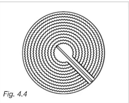
natural_image
Circular diagram with concentric wavy lines and a central dot, labeled 'Fig. 4.4' (no text or symbols within the diagram itself)Do not scratch the cooktop with cutting or sharp objects.
Do not use the cooktop as a work surface.
Caution! the cooking hob becomes very hot during operation.
Keep children well out of reach.
natural_image
Simple diagram of two vertical bars inside a circle, labeled Fig. 4.5 (no text or symbols on the bars themselves)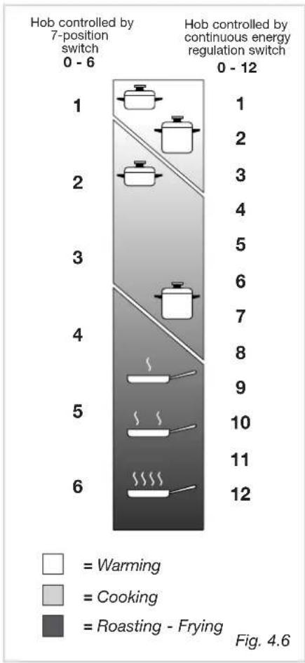
bar_stacked
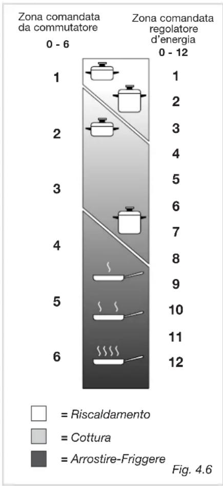
| Category | Warming | Cooking | Roasting - Frying | | :--- | :--- | :--- | :--- | | 1 | 0 | 0 | 0 | | 2 | 0 | 0 | 0 | | 3 | 0 | 0 | 0 | | 4 | 0 | 0 | 0 | | 5 | 0 | 0 | 0 | | 6 | 0 | 0 | 0 | | 7 | 0 | 0 | 0 | | 8 | 0 | 0 | 0 | | 9 | 0 | 0 | 0 | | 10 | 0 | 0 | 0 | | 11 | 0 | 0 | 0 | | 12 | 0 | 0 | 0 | Hob controlled by 7-position switch; Hob controlled by continuous energy regulation switch; Warming; Cooking; Roasting - Frying; Fig. 4.6HINTS FOR SAFE USE OF THE HOBS
- Before switching on, check which knob controls the required hob. You are advised to place the saucepan on the hob before switching on and to take it off after switching off.
- Use saucepans with an even flat bottom (be careful of cast iron saucepans). Uneven bottoms can scratch the pyroceram surface. Check that the bottom is clean and dry.
- Check that the saucepan handle does not protrude from the top to avoid knocking it over. This precaution also makes it more difficult for children to reach the saucepan.
- Do not use the top if the surface is broken or damaged.
- Do not bend over the hobs when they are on.
- Do not leave aluminium foil, greaseproof paper etc. or plastic on the hob when it is hot.
– Remember that the hobs stay hot for quite a long time (approx. 30 min.) after they have been switched off. - Scrupulously follow the cleaning instructions.
- D o not drop heavy or sharp objects on the glass ceramic cooktop.
- If you note a crack in the cooktop, switch the appliance off immediately and call the After-Sales Service.
- If the cooktop has halogen lamps, do not stare at them.
- Never cook the food directly on the glass ceramic cooktop, but in special pans or containers.
ELECTRIC HOTPLATE USAGE TABLE
| Position of switch | Type of cooking | |
| 0 | 0 | Switched OFF |
| 12 | 12 | For melting operations (of butter or chocolate) |
| 2 | 234 | To keep foods warm or heat small quantities of water. |
| 3 | 456 | To heat greater quantities of water and to whip creams and sauces. |
| 34 | 67 | Slow boiling, e.g. spaghetti, soups, boiled meats, to continue steam heating of roast meats and stews. |
| 4 | 78 | For all kinds of fried foods, steaks, cutlets and cooking without a lid. |
| 45 | 8910 | For browning of meat, cooked potatoes, fried fish and for boiling large quantities of water. |
| 6 | 1112 | Rapid frying, grilled steaks, |
GENERAL RECOMANDATION
√ Before you begin cleaning you must ensure that the hob is switched off.
It is advisable to clean when the appliance is cold and especially when cleaning the enamelled parts.
√ All enamelled surfaces have to be washed with soapy water or some other non-abrasive product with a sponge and are to be dried preferably with a soft cloth.
√ Avoid leaving alkaline or acid substances (lemon juice, vinegar etc.) on the surfaces.
ENAMELLED PARTS
√ All the enamelled parts must be cleaned with a sponge and soapy water only or other non-abrasive products.
√ Dry preferably with a chamois leather.
If acid substances such as lemon juice, tomato conserve, vinegar etc. are left on the enamel for a long time they will etch it, making it opaque.
STAINLESS STEEL ELEMENTS
√ Stainless steel parts must be rinsed with water and dried with a soft and clean cloth or with a chamois leather.
√ For difficult dirt, usea specific non-abrasive product available commercially or a little hot vinegar.
√ Note: regular use could cause discolouring around the burners, because of the high flame temperature.
CONTROL KNOB
√ The control knobs may be removed for cleaning but care should be taken not to damage the seal.
GLASS LID (optional)
Electric plates and gas models
√ Do not close the glass lid when the electrical plates are still hot and when the oven, installed below the cooking hob is on or still hot.
√ Do not rest hot pans or heavy objects on the cooker lid.
√ Remove any spillages from the surface of the lid before opening.
GAS TAPS
√ In the event of operating faults in the gas taps, call the Service Department.
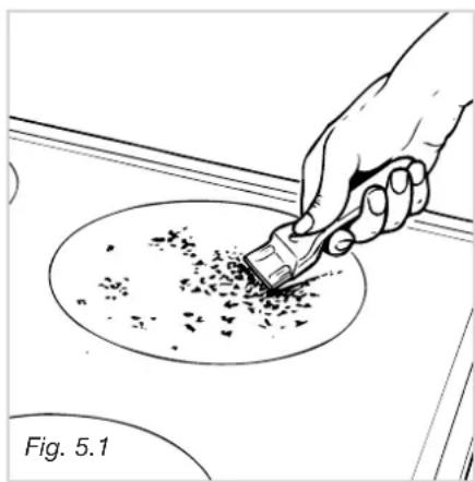
VITROCERAMIC HOB
Before cleaning the top, make sure that it is switched off.
Remove any encrustation using a special scraper which can be bought (fig. 5.1).
Remove dust using a damp cloth.
Detergents can be used as long as they are not abrasive or corrosive.
All residues of detergent must be eliminated with a damp cloth.
Keep all objects that could be melted by the heat away from the top: plastic objects, aluminium foil, sugar or sugary products.
If an object melts on the top, remove immediately (while the top is still hot) using the special scraper to avoid permanent damage to the pyroceram surface.
Avoid using knives and pointed objects as they could damage the surface of the top.
Also avoid using abrasive sponges or wire wool which can permanently scratch the pyroceram surface.
CLEANING ELECTRIC HOTPLATES
√ Always clean when the hotplate is tepid.
√ Use a soft cloth, dampened with water, and a little salt. To finish off, use a soft cloth with a little oil.
√ Do not use water, to avoid the formation of rust.
Do not scratch the cooktop with cutting or sharp objects.
Do not use the cooktop as a work surface.
Do not use steam jet cleaners because the humidity could infiltrate into the appliance making it dangerous.
natural_image
Hand using a tool to brush or mark on a circular object, labeled 'Fig. 5.1' (no other text or symbols)
text_image
C F T S Fig. 5.2BURNERS AND GRIDS
√ These parts can be removed and cleaned with appropriate products.
√ After cleaning, the burners and their flame distributors must be well dried and correctly replaced.
√ It is very important to check that the burner flame distributor and the cap has been correctly positioned - failure to do so can cause serious problems.
√ In appliances with electric ignition keep the electrode clean so that the sparks always strike.
√ Note: To avoid damage to the electric ignition do not use it when the burners are not in place.
CORRECT REPLACEMENT OF THE BURNERS
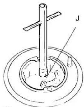
It is very important to check that the burner flame distributor F and the cap C has been correctly positioned (see figs. 5.2 and 5.6) failure to do so can cause serious problems.
Check that the electrode "S" (fig. 5.2) is always clean to ensure trouble-free sparking.
Check that the probe "T" (fig. 5.2) next to each burner is always clean to ensure correct operation of the safety valves.
Both the probe and ignition plug must be very carefully cleaned.
natural_image
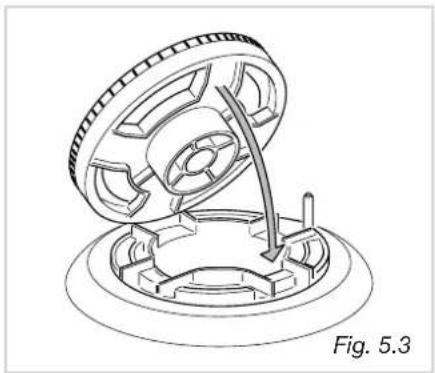
Mechanical assembly diagram showing a rotating component with a curved arrow indicating motion (no text or symbols)TRIPLE RING BURNER
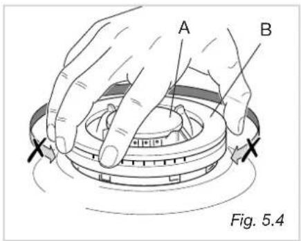
The triple ring burner must be correctly positioned (see fig. 5.3); the burner rib must be enter in their logement as shown by the arrow.
Then position the cap A and the ring B (fig. 5.4 - 5.5).
The burner correctly positioned must not rotate (fig. 5.4).
text_image
A B Fig. 5.4
text_image
Fig. 5.5 Fig. 5.6Installation advice

INSTALLATION
IMPORTANT
- The appliance should be installed, regulated and adapted to function with other types of gas by a QUALIFIED INSTALLATION TECHNICIAN.
Failure to comply with this condition will render the guarantee invalid. - The appliance must be installed in compliance with regulations in force.
- Installation technicians must comply to current laws in force concerning ventilation and the evacuation of exhaust gases.
- Always unplug the appliance before carrying out any maintenance operations or repairs.
√ The appliance must be housed in heat-resistant units.
√ These tops are designed to be embedded into kitchen fixtures measuring 600 mm in depth.
√ The walls of the units must not be higher than work top and must be capable of resisting temperatures of 75 °C above room temperature.
√ Do not install the appliance near inflammable materials (eg. curtains).
GAS COOKING HOBS
text_image
288 510 30 50 490 ° 270 ° Fig. 6.1a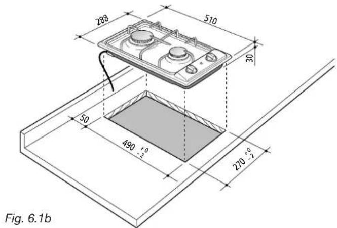
text_image
288 510 30 50 490 +0 -2 270 +0 -2 Fig. 6.1bTECHNICAL INFORMATION FOR THE INSTALLER
Before installing the cooktop, remove the protective film.
This cooktop can be built into a working surface 20 to 40 mm thick and 600 mm deep.
In order to install the cooker top into the kitchen fixture, a hole with the dimensions shown in figs. 6.1a - 6.1b has to be made, keeping in consideration the following:
– within the fixture, between the bottom side of the cooker top and the upper surface of any other appliance or internal shelf there must be a clearance of at least 30 mm;
- the cooker top must be kept no less than 100 mm away from any side wall;
- the cooker top must be kept at a distance of no less than 50 mm from the rear wall.
– there must be a distance of at least 650 mm between the hob and any wall cupboard or extractor hood positioned immediately above (see fig. 6.2)
- the coatings of the walls of the unit or appliances near the cooktop must be heat resistant ("Y" protection against heating in compliance with standards EN 60335-2-6).
text_image
0 0 450 mm 650 mm 0 0 0 Fig. 6.2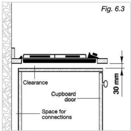
text_image
Fig. 6.3 Clearance Cupboard door Space for connections 30 mm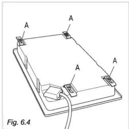
text_image
A A A A Fig. 6.4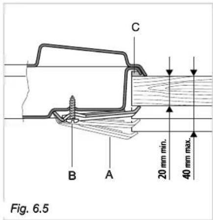
text_image
C B A 20 mm min. 40 mm max. Fig. 6.5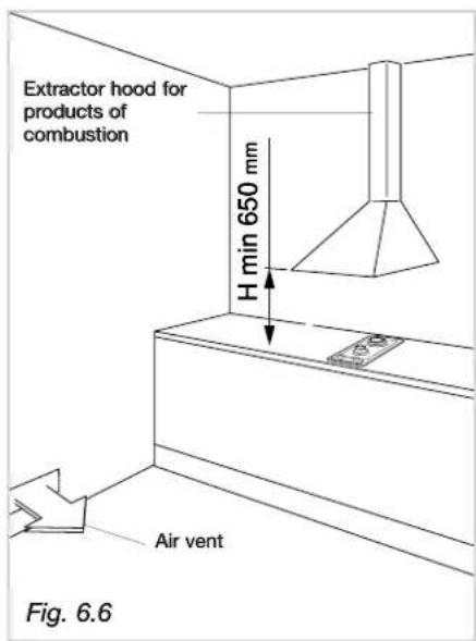
text_image
Extractor hood for products of combustion H min 650 mm Air vent Fig. 6.6WITH CUPBOARD DOORS (fig. 6.3)
The fixture has to be made according to specific requirements in order to prevent the gas burners from going out, even when the flame is turned down to minimum, due to pressure changes while opening or closing the cupboard doors.
It is recommended that a 30 mm clearance be left between the cooker top and the fixture surface beneath it.
FASTENING THE COOKTOP (fig. 6.4)
Each cooktop is supplied with a set of tabs and screws to fasten it on units with a working surface from 2 to 4 cm deep.
The kit includes 4 tabs "A" and 4 self-threading screws "B".
√ Cut the unit.
√ Stretch gasket "C" over the edge of the hole made, being careful to overlay the junction edges.
√ Turn the cooktop over and put tabs "A" into the mountings; only tighten screws "B" a few turns.
Make sure that the tabs are mounted correctly as shown in the figure.
√ Put the cooktop into the hole cut into the unit and position it correctly.
√ Put tabs "A" into place and tighten screws "B" until the cooktop is completely secured.
√ Using a sharp tool cut off the part of gasket "C" which protrudes from the cooktop.
CHOOSING SUITABLE SURROUNDINGS (for gas models)
The room where the gas appliance is to be installed must have a natural flow of air so that the gas can burn (in compliance with the current laws in force).
The flow of air must come directly from one or more openings made in the outside walls with a free area of at least 100 cm ^2 .
If the appliance does not have a no-flame safety device this opening must have an area of at least 200 cm ^4 .
The openings should be near the floor and preferably on the side opposite the exhaust for combustion products and must be so made that they cannot be blocked from either the outside or the outside.
When these openings cannot be made, the necessary air can come from an adjacent room which is ventilated as required, as long as it is not a bedroom or a danger area (in compliance with the current laws in force).
In this case, the kitchen door must allow the passage of the air.
text_image
Extractor hood for products of combustion H min 650 mm Air vent Fig. 6.6
text_image
Electric fan to extract products of combustion Air vent Fig. 6.7DISCHARGING PRODUCTS OF COMBUSTION
Extractor hoods connected directly to the outside must be provided, to allow the products of combustion in the gas appliance to be discharged (fig. 6.6).
If this is not possible, an electric fan may be used, attached to the external wall or the window; the fan should have a capacity to circulate air at an hourly rate of 3-5 times the total volume of the kitchen (fig. 6.7).
The fan can only be installed if the room has suitable vents to allow air to enter, as described under the heading "Choosing suitable surroundings" (in compliance with the current laws in force).
text_image
288 510 30 50 490 +0 -2 270 +0 -2 Fig. 6.8a
text_image
288 510 50 490 +0 -2 270 +0 -2 Fig. 6.8bTECHNICAL INFORMATION FOR THE INSTALLER
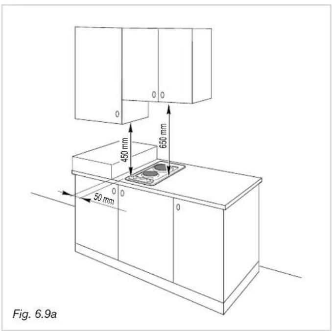
Before installing the cooktop, remove the protective film.
These cooking hobs are designed to be embedded into kitchen fixtures measuring 600 mm in depth and from 20 to 40 mm thick, for 2 electrical plates hob, and from 30 to 40 mm thick for vitroceramic hob.
In order to install the cooker top into the kitchen fixture, a hole with the dimensions shown in figs. 6.8a and 6.8b has to be made, keeping in consideration the following:
– within the fixture, between the bottom side of the cooker top and the upper surface of any other appliance or internal shelf there must be a clearance of at least 30 mm;
- the cooker top must be kept no less than 50 mm away from any side wall;
- the cooker top must be kept at a distance of no less than 50 mm from the rear wall.
- there must be a distance of at least 650 mm between the hob and any wall cupboard or extractor hood positioned immediately above (see figs. 6.9a and 6.9b).
- the coatings of the walls of the unit or appliances near the cooktop must be heat resistant ("Y" protection against heating in compliance with standards EN 60335-2-6).
Do not install the appliance near inflammable materials (eg. curtains).
text_image
Fig. 6.9a 450 mm 650 mm 50 mm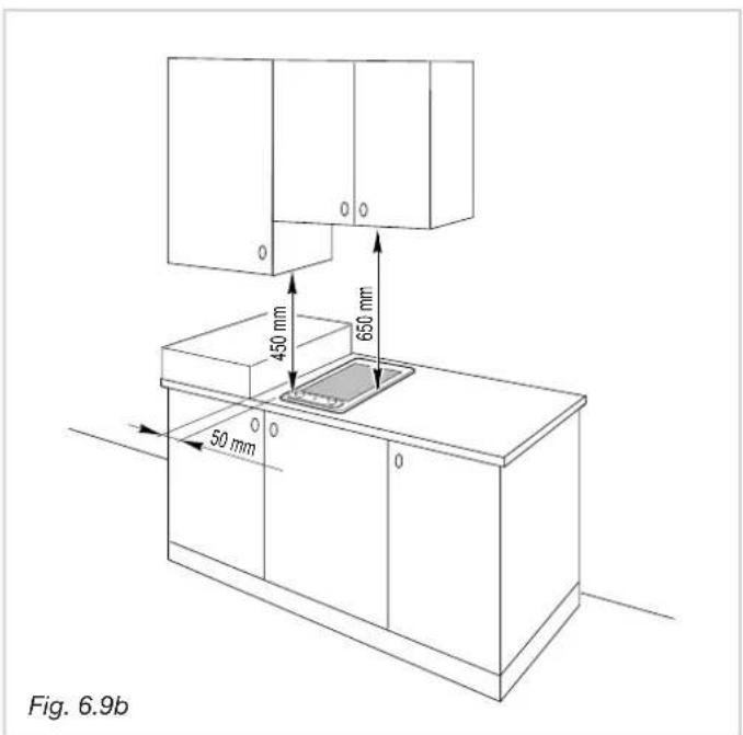
text_image
Fig. 6.9b 450 mm 650 mm 50 mm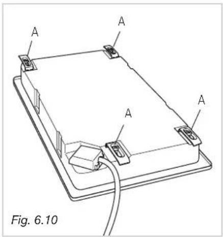
text_image
A A A A Fig. 6.10FASTENING THE COOKTOP
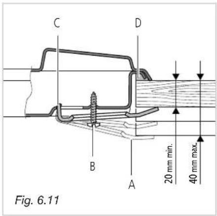
Each cooker top is provided with an installation kit including brackets and screws for fastening the top to fixture panels from 20-30 to 40 mm thick, figs. 6.11 (2 electrical plates hob) e 6.12 (vitroceramic hob).
√ Cut the unit.
√ Stretch gasket "D" over the edge of the hole made, being careful to overlay the junction edges
√ Turn the cooktop over and put tabs "A" (fig. 6.10) into the mountings, only tighten screws "B" a few turns.
Make sure that the tabs are mounted correctly as shown in the figures 6.11 and 6.12. Turn the tabs so that the cooktop can be put into the hole.
√ Put the cooktop into the hole cut into the unit and position it correctly.
√ Put tabs "A"; into place, tooth "C" of the tabs should go into the hole.
√ Tighten screws "B" until the cooktop is completely secured.
√ Using a sharp tool cut off the part of gasket "D" which protrudes from the cooktop.
text_image
C D B A 20 mm min. 40 mm max. Fig. 6.11
text_image
C D B A 30 mm min. 40 mm max. Fig. 6.12GAS CONNECTIONS
Make sure that the hob is adapted to function with the type of gas supply available (see label). If not, refer to the section headed “Adapting the appliance to function with different types of gas”.
GASES
The gases used for the operation of cooking appliances may be grouped by their characteristics into two types:
– Liquid gas: Butane gas (G 30) and Propane gas (G 31)
– Natural gas (G 20)
Connecting to gas mains:

Cat: II 2H3+
The cooktop connection (fig. 7.1a - 7.1b) is made up as follows:
√ 1 nipple "A"
√ 1 union elbow "C"
√ gaskets "F"
√ 1 conical elbow "G"
Connection to the gas main must be performed by a qualified technician, in compliance with the current laws in force.
Before connecting the appliance to the gas main, mount conical elbow "G" (supplied with appliance) onto the union elbow "C," upon which the gasket "F" has been placed.
To maintain the thickness of 3 cm, the hob is fitted with a channel to contain the connection pipe.
The gas inlet union can be turned in the direction required after the union elbow C - nipple A connection has been slackened (Fig. 7.2).
Never put it in the horizontal or vertical position.
text_image
C F A 1/2" G F G 1/2" G conical Fig. 7.1
natural_image
Line drawing of a wrench gripping a mechanical component (no text or symbols)IMPORTANT:
√ Never turn union C using force without first slackening nut A.
√ Gaskets F (Fig. 7.1) guarantee the seal of the gas connection.
Replace them whenever they are even slightly deformed or imperfect.
√ Any connection to fixed metal pipes must be done in such a way so as not to place undue stress on the hob chassis.
√ If using flexible metal pipes, make sure they are not squashed, and do not come into contact with moving parts.
√ Any flexible pipes must be so installed as to be easily inspected along their whole length. They must be changed before the expiry date (printed on the pipe itself) and not exceed 2 metres in length.
√ After connecting to the gas mains, check that the couplings are correctly sealed, using soapy solution, but never a naked flame.
ADAPTING THE APPLIANCE TO FUNCTION WITH DIFFERENT TYPES OF GAS
If a gas different from that indicated on the label is used, adapt the cooktop to this new function.
Every cooking hob is provided with a set of injectors for the various types of gas.
Injectors not supplied can be obtained from the After-Sales Service.
Select the injectors to be replaced according to the table below.
The nozzle diameters, expressed in hundredths of a millimetre, are marked on the body of each injector.
| GB INJECTORS TABLE | ||||
| Cat: II 2H3+ | NOMINAL POWER | REDUCED POWER | G30/G3128-30/37 mbar | G2020 mbar |
| BURNERS | [Hs - KW] | [Hs - KW] | ∅ injector[1/100 mm] | ∅ injector[1/100 mm] |
| Semi-rapid (SR) 1,75 0,45 65 97 | ||||
| Rapid (R) 3,00 0,75 85 115 | ||||
| Triple ring (TR) | 3,50 1,50 95 135 | |||
text_image
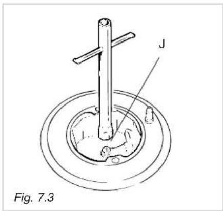
J Fig. 7.3
text_image
Fig. 7.4OPERATIONS TO BE PERFORMED WHEN SUBSTITUTING THE INJECTORS
√ Remove the gratings, the burner covers and the knobs;
√ Using a wrench substitute the nozzle injectors "J" (Fig. 7.3 - 7.4) with those most suitable for the kind of gas for which it is to be used.
The burner are conceived in such a way so as not to require the regulation of the primary air.
REGULATING THE BURNER MINIMUM SETTING
When switching from one type of gas to another, the minimum flow rate must also be correct: the flame should not go out even when passing suddenly from maximum to minimum flame.
Toregulate the flame follow the instructions below:
- Light the burner
- Set the cock valve to minimum
On gas valves provided with adjustment screw in the centre of the shaft (fig. 7.5):
- Using a screwdriver with max. diameter 3 mm, turn the screw inside the tap until the correct setting is obtained.
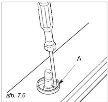
On gas valves provided with adjustment screw on the valve body (fig. 7.6):
- T urn the screw "A" to the correct setting with a screwdriver.
For G 30/G 31 gas, tighten the adjustment screw completely.
natural_image
Technical line drawing of a screwdriver with a base mount, labeled Fig. 7.5 (no text or symbols on the diagram itself)
text_image
Fig. 7.6 ALUBRICATING THE GAS TAPS
If one of the gas taps becomes difficult to turn, dismantle it, thoroughly clean with petrol and apply special high-temperature grease.
These operations must be performed by a specialised engineer.
IMPORTANT: Installation has to be carried out according to the instructions provided by the manufacturer. Incorrect installation might cause harm and damage to people, animals or objects, for which the manufacturer accepts no responsibility.
DETAILS
√ Connection to the electric power supply must be carried out by a qualified technician and following the appropriate safety regulations;
√ Before carrying out the connection to the power supply, the voltage rating of the appliance (stamped on the appliance identification plate) must be checked for correspondence to the available mains supply voltage, and the mains electric wiring should be capable of handling the cooker's power rating (also indicated on the identification plate);
√ The appliance is supplied without a power supply plug and therefore if you are not connecting directly to the mains, a standardized plug suitable for the load must be fitted.
√ The power point must be connected to a suitable earth wiring, in conformity to current safety regulations.
√ The colours of the wires in the hob power cable may not correspond with the colours marked on the terminals of your electrical plug. The plug should in any case be wired as follows:
- connect the green/yellow wire to the terminal marked with the letter PE or the earth symbol or coloured green/yellow;
- connect the blue wire to the terminal marked with the letter N or coloured black;
- connect the brown wire to the terminal marked with the letter L or coloured red.
√ It is possible to connect the appliance directly to the mains supply by means of a heavy duty switch with 3 mm minimum distance between the contacts.
√ The power supply cord must not touch against any hot surfaces and must be placed so that its temperature does not exceed 75^ C at any point along its length.
√ After having installed the appliance, the power switch or power plug must always be in a accessible position.
√ The appliance must have its own supply; any other appliances installed near it must be supplied separately.
- N.B. For connections to the mains power supply, never use adaptors, reductions or multiple power points as these may overheat and catch fire.
In the event that installation should require modifications to the mains supply wiring system, it is recommended that a qualified technician be called to carry out substitution.
The technician will also have to verify that the cross-section of the electric cables on the power point match the appliance's power rating.
A double pole switch must be provided no further than 2 metres from the appliance to the electrical supply.
If you are using the hob for the first time, or after a period of disuse, you should set the controls to position 1 for approximately 30 seconds, to dry out any humidity.
This appliance must be connected by a competent person, using fixed wiring via a DOUBLE POLE SWITCHED FUSED SPUR OUTLET.
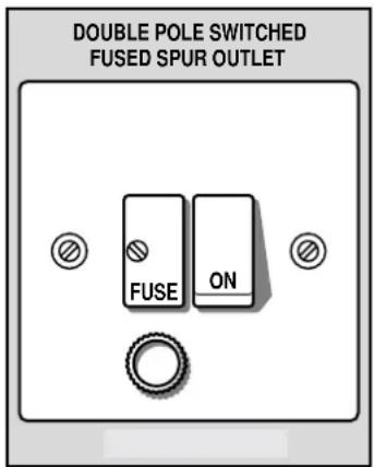
text_image
DOUBLE POLE SWITCHED FUSED SPUR OUTLET FUSE ONfor gas hobs use a 3 amp FUSE for electric hobs use a 20 amp FUSE
We recommend that the appliance is connected by a qualified electrician, who is a member of the N.I.C.E I C. and who will comply with the I.E.E. and local regulations.
The wires in the mains lead are coloured in accordance with the following code:
Green & Yellow = Earth
Blue = Neutral
Brown = Live.
As the colours of the wires in the mains lead for the appliance, may not correspond with the coloured markings identifying the terminals in your spur box, proceed as follows:
1) The wire which is coloured green and yellow must be connected to the terminal marked E (Earth) or coloured Green.
2) The wire which is coloured blue must be connected to the terminal marked N (Neutral), or coloured Black.
3) The wire which is coloured brown must be connected to the terminal marked L (Live), or coloured Red.
Connection to a good earth wiring system is absolutely essential.
The manufacturer accepts no responsibility for any inconvenience caused by failure to comply with this rule.
Before carrying out any work on the electrical section of the appliance, it must be disconnected from the mains.
If the hob surface is cracked disconnect the appliance from the mains.
text_image
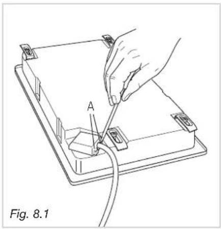
A Fig. 8.1REPAIRS
REPLACING THE POWER SUPPLY CABLE
(for 2 electrical plates and vitroceramic models)
Turn the cooktop over and unhook the terminal board cover by inserting a screwdriver into the two hooks "A" (fig. 8.1).
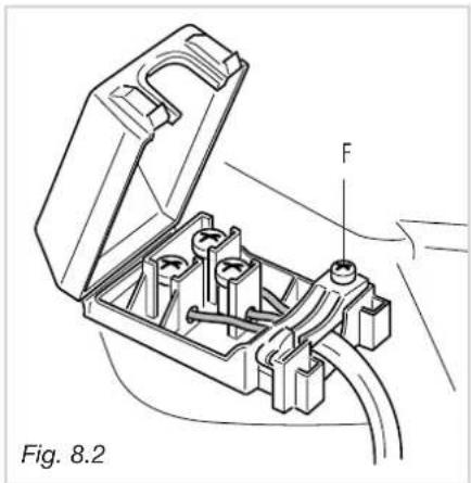
Open the cable gland by unscrewing screw "F" (fig. 8.2), unscrew the terminal screws and remove the cable.
The new supply cable, of suitable type and section, is connected to the terminal board following the diagram fig. 8.3.
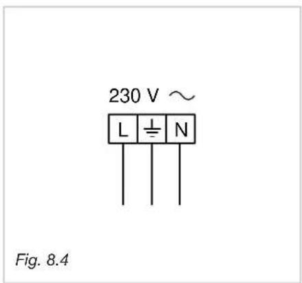
REPLACING THE POWER SUPPLY CABLE (for gas models)
- The supply cable must be replaced with a cable of the same type.
- The electrical cable must be connected to the terminal board following the diagrams of fig. 8.4.
natural_image
Technical line drawing of an open electrical connector with labeled component 'F' (no text or symbols beyond label)FEEDER CABLE SECTION
COOKING HOB GAS
type "H05V2V2-F"
resistance to temperatures of 90°C
230 V\~ 3 x 0.75 mm 2

text_image
230 V ~ L1 (L)2 N PE Fig. 8.3COOKING HOB ELECTRIC HOTPLATES
The external diameter of the supply cable must not be more than 9 mm.
tipo "H05RR-F"
230 V\~ 3 x 1,50 mm 2
COOKING HOB VITROCERAMIC
The external diameter of the supply cable must not be more than 9 mm.
type "H05RR-F"
230 V\~ 3 x 1,50 mm 2
text_image
230 V ~ L N Fig. 8.4The manufacturer cannot be held responsible for possible inaccuracies due to printing or transcription errors in the present booklet.
The manufacturer reserves the right to make all modifications to its products deemed necessary for manufacture or commercial reasons at any moment and without prior notice, without jeopardising the essential functional and safety characteristics of the appliances.
Cher client
natural_image
Simple line drawing of a circular object with internal vertical lines and two droplet symbols below (no text or labels)Fig. 2.1a
natural_image
Symbolic diagram with a circle containing vertical lines and droplets, no readable text or labelsFig. 2.1b

Fig. 2.2

natural_image
Simple line drawing of a hat with arrows indicating motion or change, no text or symbols presentBRULEURS A GAZ
text_image
INEXACT Fig. 2.6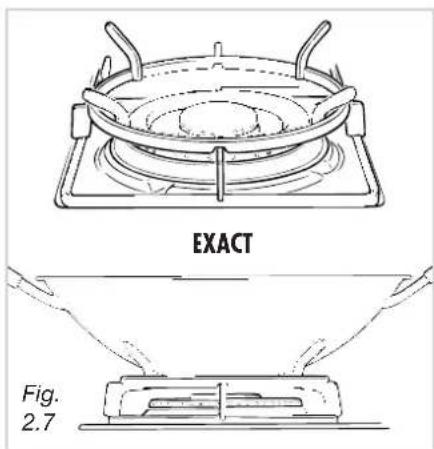
text_image
EXACT Fig. 2.7
text_image
1. 2. 3. 4 5 6 0Fig. 3.1
text_image
0 12. 11. 10. 9. 8° 7° 6° 5° 4 3 2 1 0 .1Fig. 3.2
bar_stacked
| Position | Réchauffage | Cuisson | Rôtissage - friture | | -------- | ----------- | ------- | ------------------- | | 1 | 0 | 1 | 0 | | 2 | 0 | 2 | 0 | | 3 | 0 | 3 | 0 | | 4 | 0 | 4 | 0 | | 5 | 0 | 5 | 0 | | 6 | 0 | 6 | 0 | | 7 | 0 | 7 | 0 | | 8 | 0 | 8 | 0 | | 9 | 0 | 9 | 0 | | 10 | 0 | 10 | 0 | | 11 | 0 | 11 | 0 | | 12 | 0 | 12 | 0 |PLAQUE NORMALE
natural_image
Three identical line drawings of a cooking pot with a lid, a lid with crossed-out panes, and a lid with crossed-out panes (no text or symbols)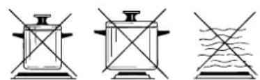
natural_image
Three diagrams showing different types of laboratory or filtration setups with no visible text or symbolsFig. 3.3
natural_image
Circular maze pattern with concentric rings and a central loop, labeled Fig. 4.3 (no text or symbols on the maze itself)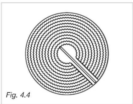
natural_image
Circular diagram with concentric wavy lines and a central dot, labeled 'Fig. 4.4' (no text or symbols within the diagram itself)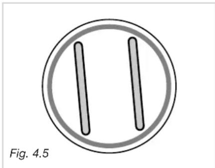
natural_image
Simple diagram of two vertical bars inside a circle, labeled Fig. 4.5 (no text or symbols on the bars themselves)natural_image
Hand using a tool to brush or mark on a circular object, labeled 'Fig. 5.1' (no other text or symbols)
text_image
C F T S Fig. 5.2BRULEURS ET GRILLES
natural_image
Mechanical assembly diagram showing a rotating component with a curved arrow indicating motion (no text or symbols)EVACUATION DES PRODUITS DE COMBUSTION
√ 1 raccord coudé "C"
√ 1 raccord coudé "C"
√ 1 raccord conique "G"
text_image
C F A 1/2" G F G 1/2" G conical Fig. 7.1bIMPORTANT:
natural_image
Line drawing of a hand using a wrench to press a valve on a mechanical component (no text or symbols)Fig. 7.2
FR
BE
TABLEAUX DES INJECTEURS
| Cat: II 2E+3+ | Débit nominal | Débit reduit | G30/G3128-30/37 mbar | G20/G2520/25 mbar |
| BURNERS | [Hs - kW] | [Hs - kW] | ∅ injecteur[1/100 mm] | ∅ injecteur[1/100 mm] |
| Semi-rapide (SR) 1,75 0,45 65 97 | ||||
| Rapide (R) 3,00 0,75 85 115 | ||||
| Triple couronne (TC) 3,50 1,50 95 135 | ||||
text_image
JFig. 7.3
ADAPTATION AUX DIFFERENTS TYPES DE GAZ
natural_image
Technical line drawing of a mechanical assembly with a central shaft and base, labeled 'J' (no text or symbols beyond label)Fig. 7.4
REGLAGE DU MINIMUM DES BRULEURS A GAZ
natural_image
Technical line drawing of a screwdriver with a base mount, labeled Fig. 7.5 (no text or symbols on the diagram itself)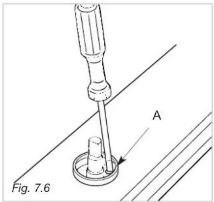
text_image
Fig. 7.6 ALUBRIFICATION DES ROBINETS DE GAZ
natural_image
Technical line drawing of an open electrical connector with labeled component 'F' (no text or symbols beyond label)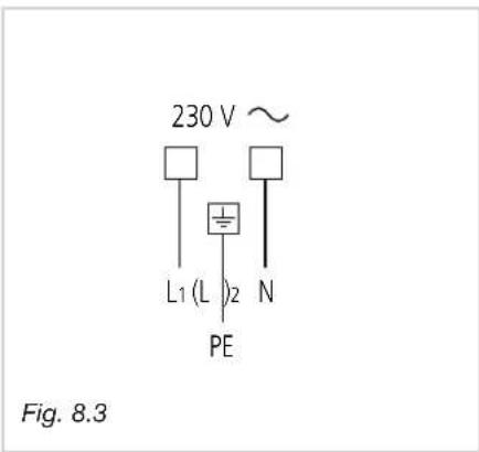
text_image
230 V ~ L1 (L)2 N PE Fig. 8.3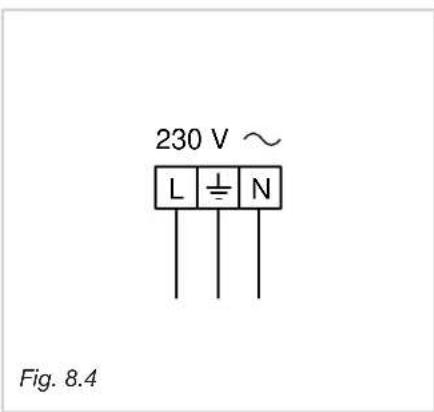
text_image
230 V ~ L ± N Fig. 8.4REPARATIONS
natural_image
Simple line drawing of a circular object with internal vertical lines and two droplet symbols below (no text or labels)Fig. 2.1a

natural_image
Symbolic diagram with a circle containing vertical lines and droplets, no readable text or labelsFig. 2.1b

Fig. 2.2
natural_image
Simple line drawing of a hat with arrows indicating motion or change, no text or symbols presentQuemadores de gas
natural_image
Simple line drawing of a hat with arrows indicating motion or change, no text or symbols presentFig. 2.3
natural_image
Circular maze pattern with concentric rings and a central loop, labeled 'Fig. 4.3' (no other text or symbols)
natural_image
Circular diagram with concentric wavy lines and a central rod, labeled 'Fig. 4.4' (no text or symbols within the diagram itself)natural_image
Simple diagram of two vertical bars inside a circle, labeled Fig. 4.5 (no text or symbols on the bars themselves)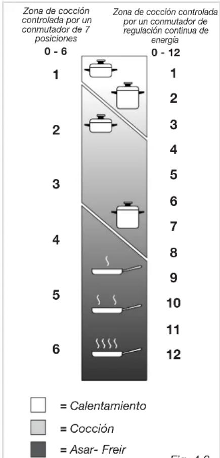
bar_stacked
| Zone | 0 - 6 | 0 - 12 | |---|---|---| | 1 | Covenon | 1 | | 2 | Covenon | 2 | | 3 | Covenon | 3 | | 4 | Covenon | 4 | | 5 | Covenon | 5 | | 6 | Asar-Freir | 6 | | 7 | Asar-Freir | 7 | | 8 | Asar-Freir | 8 | | 9 | Asar-Freir | 9 | | 10 | Asar-Freir | 10 | | 11 | Asar-Freir | 11 | | 12 | Asar-Freir | 12 |Fig. 4.6
CONSEJOS PARA UN USO SEGURO DE LA PLACA
natural_image
Hand using a tool to brush or mark on a circular object, labeled 'Fig. 5.1' (no other text or symbols)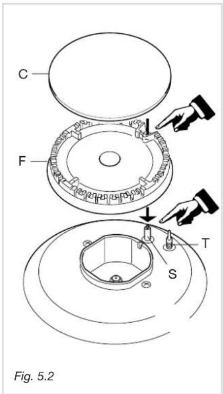
text_image
C F T S Fig. 5.2QUEMADORES Y PARRILLAS
natural_image
Mechanical assembly diagram showing a rotating component with a curved arrow indicating motion (no text or symbols)natural_image
Line drawing of a hand using a wrench to adjust a mechanical component (no text or symbols)IMPORTANTE:
natural_image
Technical diagram of a mechanical assembly with labeled component J (no text or symbols present)Fig. 7.4
natural_image
Technical line drawing of a screwdriver with a base mount, labeled Fig. 7.5 (no text or symbols on the diagram itself)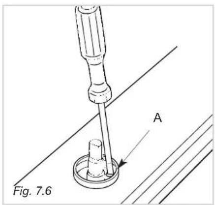
text_image
Fig. 7.6 AGRIFOS DE GAS
natural_image
Technical line drawing of an open electrical connector with labeled component 'F' (no text or symbols beyond label)
text_image
230 V ~ L1 (L)2 N PE Fig. 8.3
text_image
230 V ~ L ± N Fig. 8.4REPARACIONES
natural_image
Simple line drawing of a circular object with internal vertical lines and two droplet symbols below (no text or labels)Fig. 2.1a

natural_image
Symbolic diagram with a circle containing vertical lines and droplets, no text or labels present.Fig. 2.1b

Fig. 2.2

natural_image
Simple line drawing of a hat with arrows indicating motion or change, no text or symbols presentFig. 2.3
BOCAS A GAS - (QUEIMADORES)
natural_image
Circular maze pattern with concentric rings and a central loop, labeled 'Fig. 4.3' (no text or symbols within the diagram itself)
natural_image
Circular diagram with concentric wavy lines and a central dot, labeled 'Fig. 4.4' (no text or symbols within the diagram itself)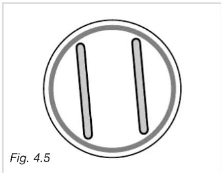
natural_image
Simple diagram of two vertical bars inside a circle, labeled Fig. 4.5 (no text or symbols on the bars themselves)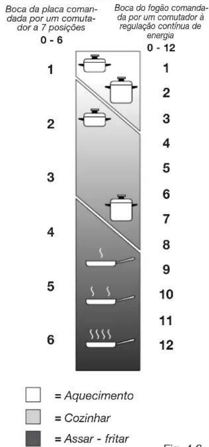
natural_image
Hand using a tool to brush or mark on a circular object, labeled 'Fig. 5.1' (no other text or symbols)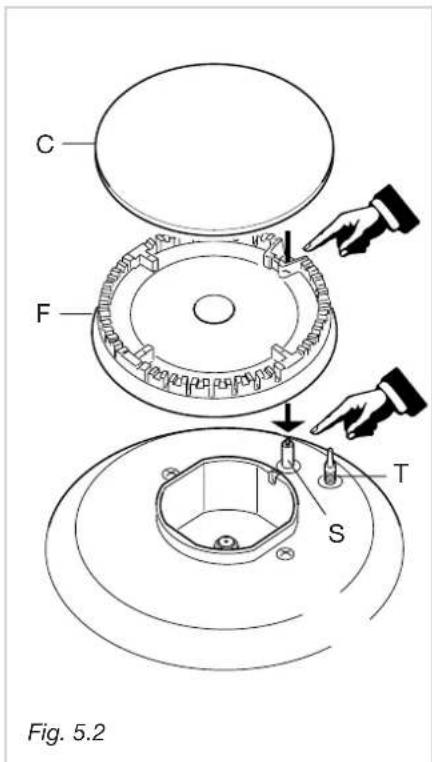
text_image
C F T S Fig. 5.2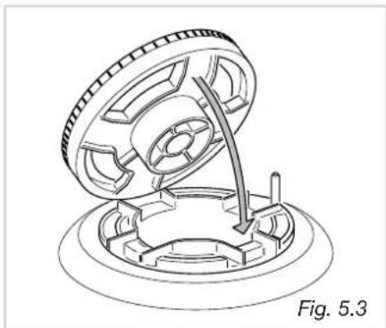
natural_image
Technical line drawing of a mechanical component with an open lid and internal gear mechanism (no text or symbols)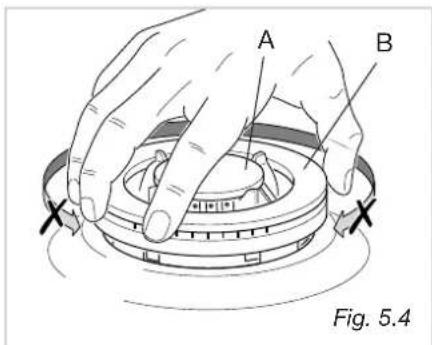
text_image
A B Fig. 5.4BOCAS DE GÁS E GRELHAS
natural_image
Cross-sectional diagram of a mechanical assembly showing internal components and directional arrows (no text or labels)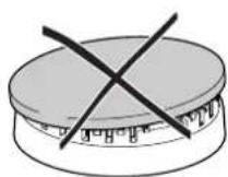
natural_image
Simple line drawing of a circular object with a checkmark arrow pointing downward (no text or symbols)Fig. 5.5
Fig. 5.6
natural_image
Line drawing of a wrench gripping a mechanical component (no text or symbols)| PT TABELAS DOS INJECTORES | ||||
| Cat: II 2H3+ | VAZÃOMÁX | VAZÃOMÍN | G30/G3128-30/37 mbar | G2020 mbar |
| BOCAS DE GÁS | [Hs - kW] | [Hs - kW] | ∅ injector[1/100 mm] | ∅ injector[1/100 mm] |
| Semi-rápida (SR) 1,75 | 0,45 65 97 | |||
| Rápida (R 3,00 0,75 85 | 115 | |||
| Coroa tripla (TC) 3,50 | 1,50 95 135 | |||

text_image
J Fig. 7.3OPERAÇÕES A SEGUIR PARA A SUBSTITUIÇÃO DOS INJECTORES
natural_image
Technical line drawing of a mechanical component with labeled part 'J' and directional arrow (no text or symbols beyond label)REGULAÇÃO DO MÍNIMO DAS BOCAS DE GÁS
natural_image
Technical line drawing of a screwdriver with a base mount, labeled Fig. 7.5 (no text or symbols on the diagram itself)
text_image
Fig. 7.6 ABOTÕES DO GAS
natural_image
Technical line drawing of an open electrical connector with labeled component 'F' (no text or symbols beyond label)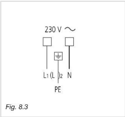
text_image
230 V ~ L1 (L)2 N PE Fig. 8.3
text_image
230 V ~ L ± N Fig. 8.4REPARAÇÕES
natural_image
Simple line drawing of a circular object with internal vertical lines and two droplet symbols below (no text or labels)afb. 2.1a

natural_image
Symbolic diagram with a circle containing vertical lines and droplets, no text or labels present.afb. 2.1b

afb. 2.2

natural_image
Simple line drawing of a hat with arrows indicating motion or change, no text or symbols presentGASBRANDERS
natural_image
Line drawing of a gas stove with cooling pan and side handles (no text or symbols)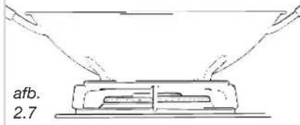
text_image
afb. 2.7
text_image
1. 2. 3. 4 5 6 0afb. 3.1

text_image
0 12. 11. 10. 9. 8° 7° 6° 5° 4 3 2 1 0 .1afb. 3.2
bar_stacked
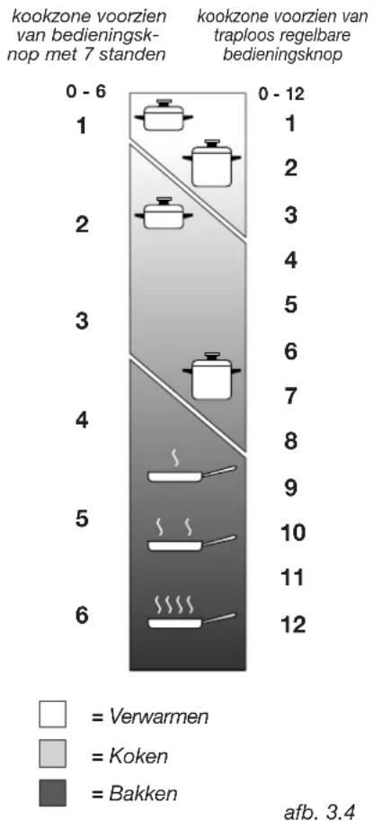
| Category | Verwarmen | Koken | Bakken | |---|---|---|---| | 0 - 6 | 1 | 2 | 0 | | 1 | 2 | 3 | 0 | | 2 | 3 | 4 | 0 | | 3 | 5 | 6 | 0 | | 4 | 7 | 8 | 0 | | 5 | 9 | 10 | 0 | | 6 | 11 | 12 | 0 | afb. 3.4NORMALE ELEKTRISCHE KOOKZONE
"3 circuit" kookzone (afb. 4.3)
natural_image
Circular maze pattern with concentric rings and a central cutout (no text or symbols)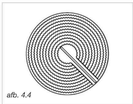
natural_image
Circular diagram with concentric wavy lines and a central dot, labeled 'afb. 4.4' (no other text or symbols)natural_image
Simple diagram of two vertical bars inside a circle, labeled 'afb. 4.5' (no text or symbols on the bars themselves)natural_image
Hand using a tool to brush or scrape material over a circular object, labeled 'afb. 5.1' (no other text or symbols)
text_image
C F T S afb. 5.2BRANDERS EN ROOSTERS
natural_image
Mechanical assembly diagram showing a rotating component with a curved arrow indicating motion (no text or symbols)BRANDER MET DRIEDUBBELE KRANS
text_image
C F A 1/2" G F G 1/2" G conical afb. 7.1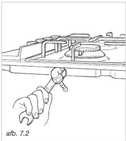
natural_image
Line drawing of a wrench gripping a mechanical component (no text or symbols)natural_image
Technical line drawing of a screwdriver with a base mount, no text or symbols present