PGVX 965 GHI - Cooker DELONGHI - Free user manual and instructions
Find the device manual for free PGVX 965 GHI DELONGHI in PDF.
Frequently Asked Questions - PGVX 965 GHI DELONGHI
Download the instructions for your Cooker in PDF format for free! Find your manual PGVX 965 GHI - DELONGHI and take your electronic device back in hand. On this page are published all the documents necessary for the use of your device. PGVX 965 GHI by DELONGHI.
USER MANUAL PGVX 965 GHI DELONGHI
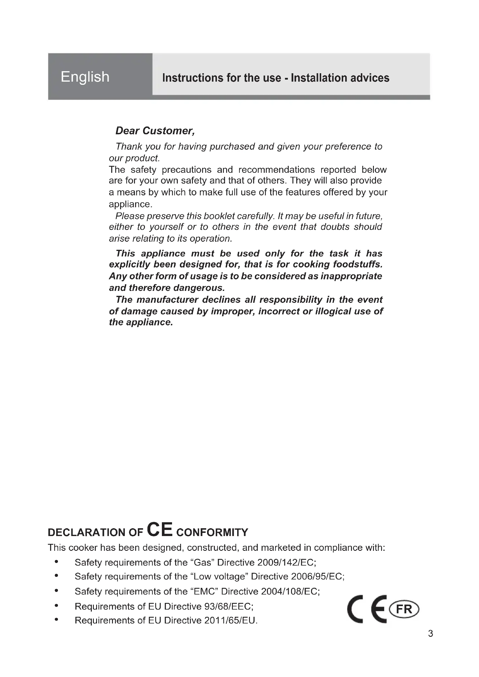
English Instructions for the use - Installation advices
The manufacturer cannot be held responsible for possible inaccuracies due to printing or transcription errors in the present booklet.
The manufacturer reserves the right to make all modifications to its products deemed necessary for manufacturer commercial reasons at any moment and without prior notice, without jeopardising the essential functional and safety characteristics of the appliances.
Thank you for having purchased and given your preference to our product.
The safety precautions and recommendations reported below are for your own safety and that of others. They will also provide a means by which to make full use of the features offered by your appliance.
Please preserve this booklet carefully. It may be useful in future, either to yourself or to others in the event that doubts should arise relating to its operation.
This appliance must be used only for the task it has explicitly been designed for, that is for cooking foodstuffs. Any other form of usage is to be considered as inappropriate and therefore dangerous.
The manufacturer declines all responsibility in the event of damage caused by improper, incorrect or illogical use of the appliance.
DECLARATION OF CE CONFORMITY
This cooker has been designed, constructed, and marketed in compliance with:
• Safety requirements of the "Gas" Directive 2009/142/EC;
- Safety requirements of the "Low voltage" Directive 2006/95/EC;
• Safety requirements of the "EMC" Directive 2004/108/EC;
- Requirements of EU Directive 93/68/EEC;
- Requirements of EU Directive 2011/65/EU.
IMPORTANT SAFETY PRECAUTIONS AND RECOMMENDATIONS
IMPORTANT: This appliance is designed and manufactured solely for the cooking of domestic (household) food and is not suitable for any non domestic application and therefore should not be used in a commercial environment.
The appliance guarantee will be void if the appliance is used within a non domestic environment i.e. a semi commercial, commercial or communal environment.
Read the instructions carefully before installing and using the appliance.
• After having unpacked the appliance, check to ensure that it is not damaged and that the oven door closes correctly.
In case of doubt, do not use it and consult your supplier or a professionally qualified technician.
- Packing elements (i.e. plastic bags, polystyrene foam, nails, packing straps, etc.) should not be left around within easy reach of children, as these may cause serious injuries.
- Some appliances are supplied with a protective film on steel and aluminium parts. This film must be removed before using the appliance.
- IMPORTANT: The use of suitable protective clothing/gloves is recommended when handling or cleaning this appliance.
- Do not attempt to modify the technical characteristics of the appliance as this may become dangerous to use. The manufacturer declines all responsibility for any inconvenience resulting from the inobservance of this condition.
- CAUTION: this appliance must only be installed in a permanently ventilated room in compliance with the applicable regulations.
- Do not operate your appliance by means of an external timer or separate remote-control system.
- Do not carry out cleaning or maintenance operations on the appliance without having previously disconnected it from the electric power supply.
- WARNING: Ensure that the appliance is switched off before replacing the oven lamp to avoid the possibility of electric shock.
- Do not use a steam cleaner because the moisture can get into the appliance thus make it unsafe.
- Do not touch the appliance with wet or damp hands (or feet).
- Do not use the appliance whilst in barefoot.
- If you should decide not to use this appliance any longer (or decide to substitute another model), before disposing of it, it is recommended that it be made inoperative in an appropriate manner in accordance to health and environmental protection regulations, ensuring in particular that all potentially hazardous parts be made harmless, especially in relation to children who could play with unused appliances.
- The various components of the appliance are recyclable. Dispose of them in accordance with the regulations in force in your country. If the appliance is to be scrapped, remove the power cord.
• After use, ensure that the knobs are in the off position. - Children less than 8 years of age shall be kept away unless continuously supervised.
- This appliance can be used by children aged from 8 years and above and persons with reduced physical, sensory or mental capabilities or lack of experience and knowledge if they have been given supervision or instruction concerning use of the appliance in a safe way and understand the hazards involved. Children shall not play with the appliance. Cleaning and user maintenance shall not be made by children without supervision.
- The manufacturer declines all liability for injury to persons or damage to property caused by incorrect or improper use of the appliance.
-
WARNING: During use the appliance and its accessible parts become hot; they remain hot for some time after use.
-
Care should be taken to avoid touching heating elements (on the hob and inside the oven).
- The door is hot, use the handle.
- To avoid burns and scalds, young children should be kept away.
- Make sure that electrical cables connecting other appliances in the proximity of the cooker cannot come into contact with the hob or become entrapped in the oven door.
- WARNING: Unattended cooking on a hob with fat or oil can be
dangerous and may result in fire. NEVER try to extinguish a fire with water, but switch off the appliance and then cover flame e.g. with a lid or a fire blanket.
- WARNING: Danger of fire: do not store items on the cooking surfaces.
- WARNING: When correctly installed, your product meets all safety requirements laid down for this type of product category. However special care should be taken around the rear or the underneath of the appliance as these areas are not designed or intended to be touched and may contain sharp or rough edges, that may cause injury.
- FIRST USE OF THE OVEN - it is advised to follow these instructions:
– Furnish the interior of the oven as described in the chapter "CLEANING AND MAINTENANCE".
- Switch on the empty oven on max to eliminate grease from the heating elements.
- Disconnect the appliance from the electrical power supply, let the oven cool down and clean the interior of the oven with a cloth soaked in water and neutral detergent; then dry carefully.
- CAUTION: Do not use harsh abrasive cleaners or sharp metal scrapers to clean the oven door glass since they can scratch the surface, which may result in shattering of the glass.
- Do not line the oven walls with aluminium foil. Do not place baking trays or the drip tray on the base of the oven chamber.
- FIRE RISK! Do not store flammable material in the oven or in the storage compartment.
- Always use oven gloves when removing the shelves and food trays from the oven whilst hot.
- Do not hang towels, dishcloths or other items on the appliance or its handle – as this could be a fire hazard.
- Clean the oven regularly and do not allow fat or oils to build up in the oven base or tray. Remove spillages as soon as they occur.
- Do not stand on the cooker or on the open oven door.
• Always stand back from the appliance when opening the oven door to allow steam and hot air to escape before removing the food. - SAFE FOOD HANDLING: Leave food in the oven for as short a time as possible before and after cooking. This is to avoid contamination by organisms which may cause food poisoning. Take particular care during warmer weather.
- WARNING: Take care NOT to lift the cooker by the door handle.
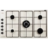
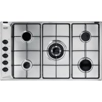
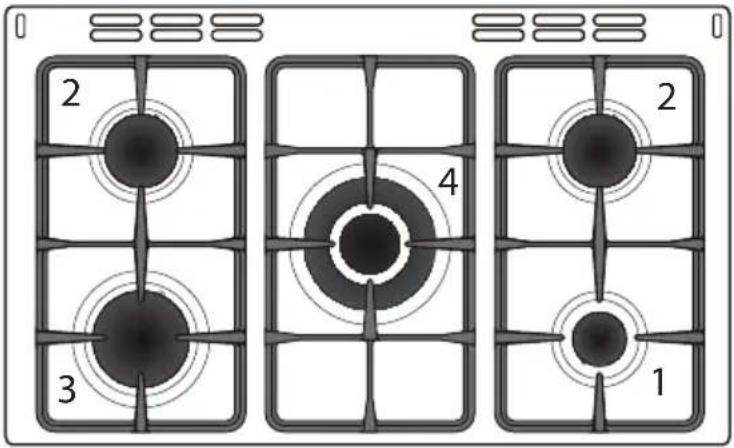
1 COOKING HOB
Fig. 1.1
text_image
2 3 4 1 2GAS BURNERS
- Auxiliary burner (A) 1,00 kW
- Semi-rapid burner (SR) 1,75 kW
- Rapid burner (R) 3,00 kW
- Triple-ring burner (TR) 3,50 kW
Notes:
- The electric ignition is incorporated in the knobs.
- The appliance has a safety valve system fitted, the flow of gas will be stopped if and when the flame should accidentally go out.
CAUTION: If the burner is accidentally extinguished, turn the gas off at the control knob and wait at least 1 minute before attempting to relight.
Fig. 2.1
text_image
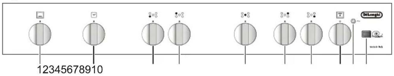
12345678910 Delenghi Service LabCONTROLS DESCRIPTION
- Gas oven thermostat control knob
- 60' alarm control knob
- Front left burner control knob
- Rear left burner control knob
- Central burner control knob
- Rear right burner control knob
- Front right burner control knob
- Electric grill and oven light control knob
- Line pilot light (electric grill)
- Fan oven switch
Note:
Your appliance has been fitted with a cooling fan to achieve optimum efficiency of the controls and to ensure lower surface temperatures are maintained.
When the oven is operating the cooling fan motor switches ON/OFF depending on temperature.
Depending on cooking temperatures and times, the cooling fan may run on even after appliance has been switched off. The duration of this time is dependent on previous cooking temperature and duration.
GAS BURNERS
Each burner is controlled by a gas tap assuring the opening and the closing of the gas supply.
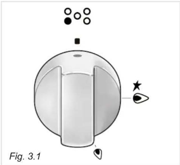
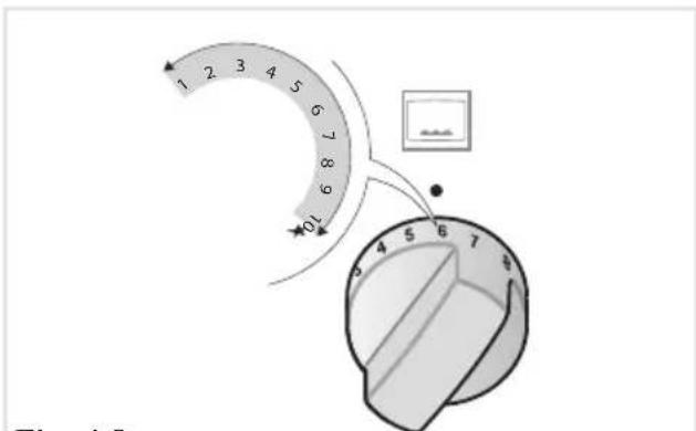
Make the symbol of the knob match with the indicator on the control panel to obtain:
- symbol

off
- symbol


- symbol

reduced rate
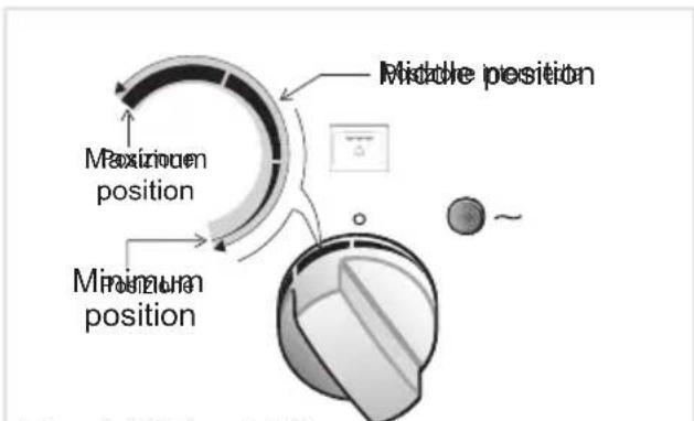
√ The maximum aperture position permits rapid boiling of liquids, whereas the minimum aperture position allows slower warming of food or maintaining boiling conditions of liquids.
√
To reduce the gas flow to minimum rotate the knob further anti-clockwise to point the indicator towards the small flame symbol.
√
Other intermediate operating adjustments can be achieved by positioning the indicator between the maximum and minimum aperture positions, and never between the maximum aperture and closed positions.
natural_image
Diagram of a mechanical knob with labeled parts and star indicators (no text or symbols on the knob itself)N.B. When the cooker is not being used, set the gas knobs to their closed positions and also close the cock valve on the gas bottle or the main gas supply line.
Caution!
The cooking hob becomes very hot during operation.
Keep children well out of reach.
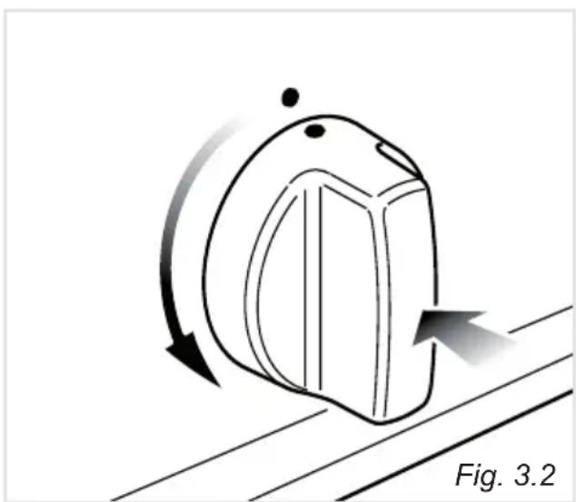
To ignite the burner, the following instructions are to be followed:
- Press in the corresponding knob and turn counter-clockwise to the full flame position marked by the ★ symbol (figs. 3.1 - 3.2) and hold the knob in until the flame has been lit.
In the case of a mains failure light the burner with a match or lighted taper.
- Wait for about ten seconds after the gas burner has been lit before letting go of the knob (valve activation delay).
- Adjust the gas valve to the desired position.
If the burner flame should go out for some reason, the safety valve will automatically stop the gas flow.
To re-light the burner, return the knob to the closed “●” position, wait for at least 1 minute and then repeat the lighting procedure.
If your local gas supply makes it difficult to light the burner with the knob set to maximum, set the knob to minimum and repeat the operation.
natural_image
Diagram of a knob with directional arrows indicating motion, labeled Fig. 3.2 (no text or symbols on the diagram itself)CHOICE OF THE BURNER
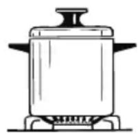
On the control panel, near every knob there is a diagram that indicates which burner is controlled by that knob.
The suitable burner must be chosen according to the diameter and the capacity used.
As an indication, the burners and the pots must be used in the following way:
DIAMETERS OF PANS WHICH MAY BE USED ON THE BURNERS
| BURNERS MINIMUM MAXIMUM | |
| Auxiliary 12 cm (*) | 14 cm |
| Semi-rapid 16 cm | 24 cm |
| Rapid 24 cm | 26 cm |
| Triple-ring 26 cm | 28 cm |
do not use pans with concave or convex bases
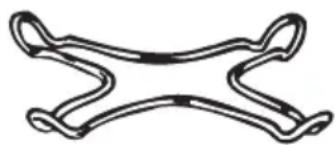
(*) with grill for small cookware: minimum diameter 6 cm
It is important that the diameter of the pot be suitable to the potentiality of the burner so as not to compromise the high output of the burners and therefore energy waste. A small pot on a large burner does not give you a boiling point in a shorter amount of time since the capacity of heat absorption of a liquid mass depends on the volume and the surface of the pot.
natural_image
Line drawing of a cooking pot on a stove (no text or symbols)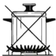
Fig. 3.3
GRATE FOR SMALL PANS
This grate is to be placed on top of the (smaller) auxiliary burner when using small
diameter pans, in order to prevent them from tipping over.
natural_image
Simple line drawing of a symmetrical mechanical or electrical component with no text or symbolsAttention: The oven door becomes very hot during operation. Keep children away.
Models with gas lid only: the cooker lid must be kept open when the oven or the grill is in use.
TECHNICAL FEATURES
The oven is furnished completely clean. It is advisable, however, upon first use, to turn the oven on to the maximum temperature to eliminate possible traces of grease from the burner.
The same operation may be done with the grill.
This oven is fitted with:
- One gas burner (6,20 kW), located at the bottom, providing electric ignition and safety device.
• One infrared rays electric grill (2200 W), placed on the top. - A fan motor positioned on the rear panel, which can be used in combination with the oven gas burner, with the electric grill or alone (without heating).
WARNING:
The door is hot, use the handle.
During use the appliance becomes hot. Care should be taken to avoid touching heating elements inside the oven.
OPERATING PRINCIPLES
Heating and cooking in the FAN ASSISTED OVEN are obtained in the following ways:
a. by normal convection
The heat is produced by the lower gas burner.
b. by forced convection
The heat produced by the oven burner is distributed throughout the oven by the fan. The hot air envelops the food in the oven, provoking a complete and rapid cooking.
It is possible to cook several dishes simultaneously.
c. by radiation
The heat is irradiated by the infra red grill element.
d. by radiation and ventilation
The radiated heat from the infra red grill element is distributed throughout the oven by the fan.
e. by ventilation
The food is defrosted by using the fan only function without heat.
SAFETY DEVICE
For safety reasons, it is not allowed to use the oven burner and the electric grill together, at the same time.
The electric grill only operates when the oven thermostat control knob is on position “●” (burner off), as:
- when the oven burner is alight a safety device stops the ignition of the electric grill;
- if the electric grill is on, the same safety device cuts off the grill element if the oven burner thermostat control knob is turned on.
OVEN BURNER
The gas flow to the burner is regulated by a thermostat which allows to maintain the oven temperature constant.
The control of the temperature is assured by a thermostatic probe positioned inside the oven. The probe must be always kept in its housing, in a clean condition, as an incorrect position or encrustment may cause an alteration in the control of the temperature.
Moreover, the thermostat is fitted with a safety valve which automatically shuts off the gas supply when the flame goes out.
text_image
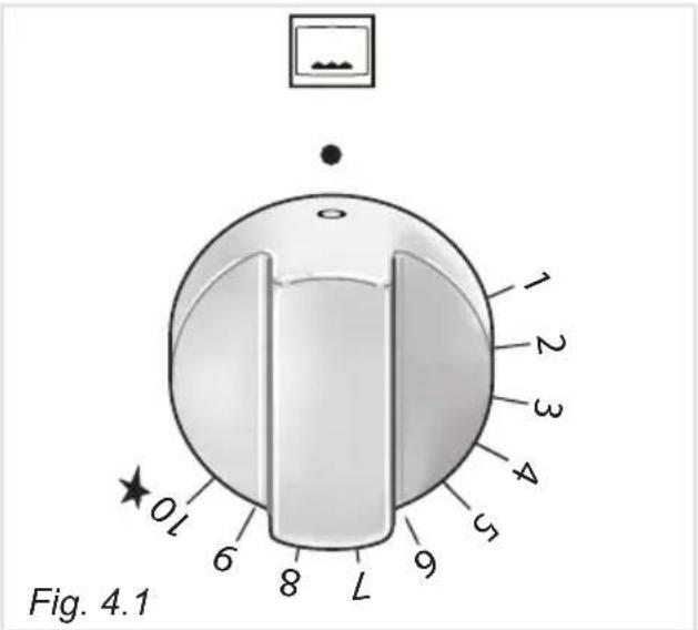
Fig. 4.1 0 L 6 8 L 9 5 4 3 2 1THERMOSTAT
The numbers 1 to 10 printed on the knob (fig. 4.1) indicate the increasing oven temperature value (see table below).
The “FAN ASSISTED GAS OVEN” column refers to the oven burner used in combination with the fan motor (forced convection cooking), while the “GAS OVEN” column refers to the oven burner used in the normal convection mode (without fan motor).
To regulate the temperature, set the knob to the chosen number.
The ★ symbol close to the position 10 indicates that the electric ignition is incorporated into the knob (activated by the knob itself).
Tab. 4.2
| THERMOSTAT GRADE TABLE | ||
| Knob position | 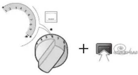 | 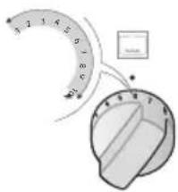 |
| FAN ASSISTED GAS OVEN | GAS OVEN | |
| 1 130 °C 130 °C | ||
| 2 140 °C 140 °C | ||
| 3 155 °C 155 °C | ||
| 4 165 °C 165 °C | ||
| 5 180 °C 180 °C | ||
| 6 190 °C 190 °C | ||
| 7 205 °C 205 °C | ||
| 8 215 °C 220 °C | ||
| 9 230 °C 235 °C | ||
| 10 ★ | 240 °C 250 °C | |
IGNITION OF THE OVEN BURNER
ATTENTION: Never turn the control knob before opening the oven door.
To light the oven burner operate as follows:
- Open the oven door to the full extent.
WARNING: Risk of explosion! The oven door must be open during this operation.
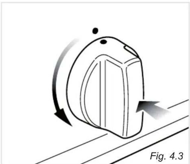
- Lightly press and turn the thermostat knob anti-clockwise (fig. 4.3) to max position ★.
- Press the knob firmly until the burner lights.
Never continue this operation for more than 15 seconds. If the burner has still not ignited, wait for about 1 minute prior to repeating the ignition.
In case of mains failure, press the knob firmly and immediately approach a lighted match or taper to the opening "A" (fig. 4.4). Never turn the gas thermostat before approaching a flame to the hole "A" of the floor.
- Wait about 10/15 seconds after the burner lighting before releasing the knob (time of priming of the valve).
- Check that the burner is lit, then close the oven door slowly and adjust the burner according to the power required.
If the flame extinguishes for any reason, the safety valve will automatically shut off the gas supply to the burner.
To re-light the burner, first turn the oven control knob to position “●” (off), wait for at least 1 minute and then repeat the lighting procedure.
For the correct use of the gas oven see the chapters "COOKING WITH FAN ASSISTED GAS OVEN" and "COOKING WITH GAS OVEN WITHOUT FAN MOTOR".
natural_image
Diagram of a knob with directional arrows indicating motion, labeled Fig. 4.3 (no text or symbols on the knob itself)
text_image
Fig. 4.4 AELECTRIC GRILL
For safety reasons, it is not allowed to use the oven burner and the electric grill together, at the same time.
The electric grill only operates when the oven thermostat control knob is on position “●” (burner off).
The electric grill is controlled by a thermostat which allows to maintain the temperature constant.
The control of the temperature is assured by a thermostatic probe positioned inside the oven.
The probe must be always kept in its housing, in a clean condition, as an incorrect position or encrustment may cause an alteration in the control of the temperature.
To switch on the grill turn the control knob clockwise and set the knob to the required temperature between minimum and maximum position (fig. 4.5).
The indicator light close to the control knob is alight when the grill is operating.
The oven lamp stays alight during the grill operation.
Grilling with the oven door closed.
For the correct use of the electric grill see the chapters “COOKING WITH FAN ASSISTED GRILL”, “COOKING WITH ELECTRIC GRILL WITHOUT FAN MOTOR” or “KEEP WARM OR SLOW HEATING”.
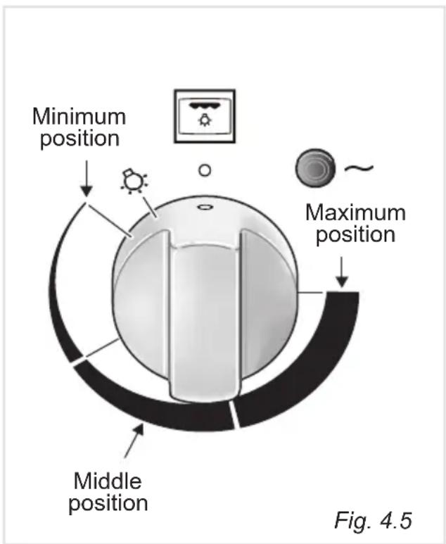
text_image
Minimum position Maximum position Middle position Fig. 4.5GRILL TEMPERATURE TABLE
| Minimum position 50 °C |
| Maximum position 250 °C |
| Intermediate positions correspond to intermediate temperatures |
Attention: The oven door becomes very hot during operation. Keep children away.
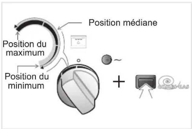
FAN MOTOR ("COMBI-GAS")
The fan motor is designed to distribute throughout the oven the heat generated by the oven gas burner or the electric grill.
The fan motor can also be used without the gas burner or the electric grill (without heating) to defrost frozen foods.
The fan is controlled by a push button (fig. 4.6).
• To operate the fan press the button.
• To switch off the fan press the button again.
IMPORTANT: When using the fan motor together with the oven gas burner, switch on the fan only after the ignition of the gas burner.
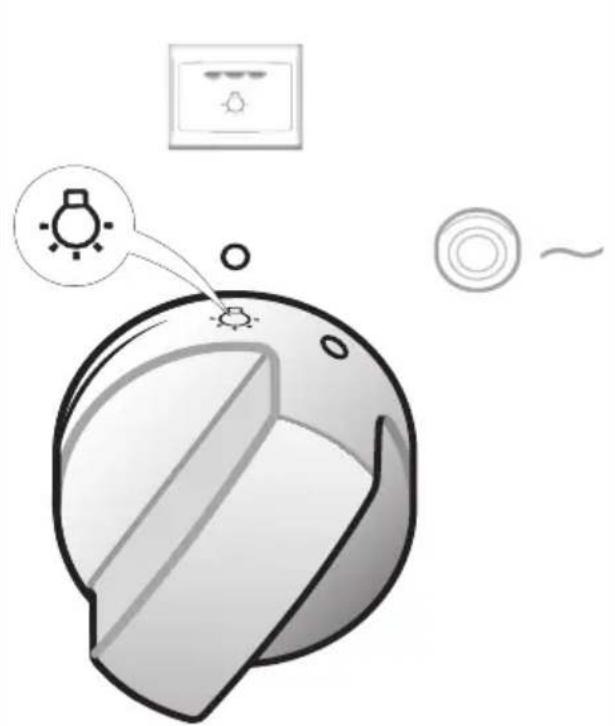
OVEN LIGHT
The oven provides an interior lamp to allow the visual inspection during the cooking.
To light the oven lamp turn the grill control knob (fig. 4.7) to the symbol 📞.
NOTE:
The oven lamp stays alight during the grill operation.
FAN MOTOR SWITCHED OFF
FAN MOTOR SWITCHED ON
Fig. 4.6
text_image
Diagram showing a fan-shaped device with a sun icon and a control panel above it, alongside a partial view of a circular component.Fig. 4.7
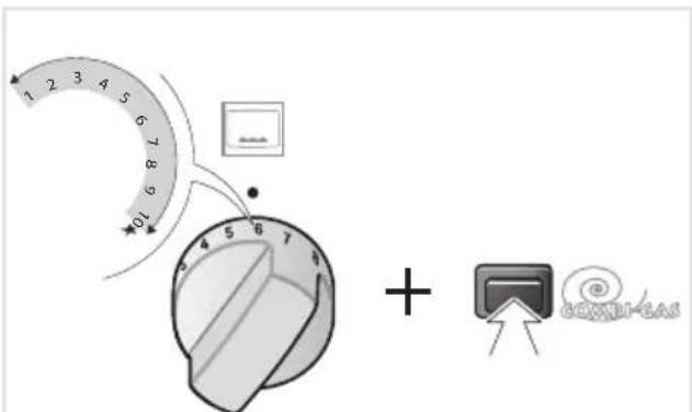
COOKING WITH FAN ASSISTED GAS OVEN
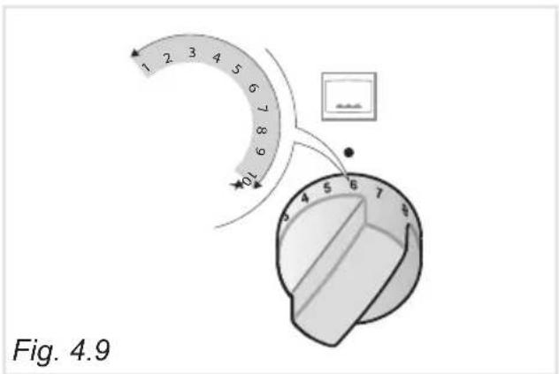
COOKING WITH GAS OVEN WITHOUT FAN MOTOR
text_image
1 2 3 4 5 6 7 8 9 01 + CONNEREASFig. 4.8
text_image
Fig. 4.9OVEN BURNER AND FAN MOTOR
After the ignition of the gas burner, close the oven door and switch on the fan motor.
Before introducing the food, preheat the oven to the desired temperature.
For a correct preheating operation, it is advisable to remove the tray from the oven and introduce it together with the food, when the oven has reached the desired temperature.
Check the cooking time and turn off the oven 5 minutes before the theoretical time to recuperate the stored heat.
OVEN BURNER WITHOUT FAN MOTOR
Before introducing the food, preheat the oven to the desired temperature.
For a correct preheating operation, it is advisable to remove the tray from the oven and introduce it together with the food, when the oven has reached the desired temperature.
Check the cooking time and turn off the oven 5 minutes before the theoretical time to recuperate the stored heat.
For a correct pre-heating, we suggest to remove tray and shelf from the oven and introduce them again after 15 minutes.
The oven accessories can withstand loads up to 14 kg. It is recommended to distribute the loads evenly.
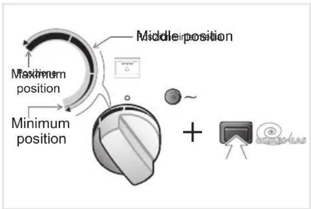
COOKING WITH FAN ASSISTED GRILL
text_image
Maximum position Minimum position Middle position + MonitorELECTRIC GRILL AND FAN MOTOR
Switch on the electric grill and the fan motor and let the oven to preheat for about 5 minutes with the door closed.
The heat is mainly diffused by radiation and the fan then distributes it throughout the oven.
Introduce the food to be cooked positioning the rack as close to the grill as possible; the dripping pan should be placed under the rack to catch the cooking juices and fats.
The fan assisted grill shall be used with the oven door closed and with the control knob in the “middle position” (figs. 4.5, 4.10); never set the fan assisted grill to higher temperatures.
It is recommended that you do not grill for longer than 30 minutes at any one time.
Attention: The oven door becomes very hot during operation.
Keep children away.
COOKING WITH ELECTRIC GRILL WITHOUT FAN MOTOR
text_image
Maximum position Minimum position Middle position ~Fig. 4.11 Fig. 4.10
ELECTRIC GRILL WITHOUT FAN MOTOR
Switch on the electric grill by turning the control knob to the "maximum position" (fig. 4.5); let to preheat for about 5 minutes with the door closed.
Introduce the food to be cooked, positioning the rack as close to the grill as possible.
Insert the drip pan under the rack to collect the cooking juices.
The grill shall be used with the oven door closed and with the knob in the “maximum position” for maximum 15 minutes; then proceed in the “middle position” (figs. 4.5, 4.11).
It is recommended that you do not grill for longer than 30 minutes at any one time.
Attention: The oven door becomes very hot during operation.
Keep children away.
KEEP WARM OR SLOW HEATING
flowchart
graph TD
    A["Maximum position"] --> B["Minimum position"]
    B --> C["Maximum position"]
    C --> D["+"]
    D --> E["Computer monitor"]
    style A fill:#f9f,stroke:#333
    style B fill:#ccf,stroke:#333
    style C fill:#cfc,stroke:#333
    style D fill:#fcc,stroke:#333
    style E fill:#cff,stroke:#333
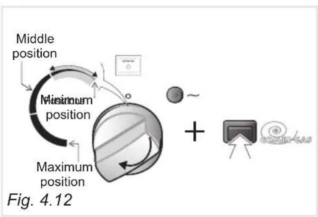
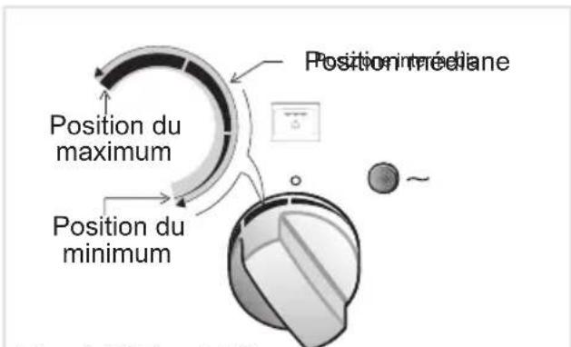
ELECTRIC GRILL WITH FAN MOTOR
Switch on the electric grill and the fan motor.
Turn the grill control knob to the “minimum position” (figs. 4.5, 4.12).
The heat is diffused throughout the oven by forced convection.
Grilling with the oven door closed.
It is recommended that you do not grill for longer than 30 minutes at any one time.
DEFROSTING FROZEN FOODS
text_image
combigas Fig. 4.13FAN ONLY
Switch on the fan motor only.
The gas oven control knob shall be in the “● off position.
The electric grill control knob shall be in the "O" off position (or in the -light position).
The defrosting is done by simple ventilation without heat.
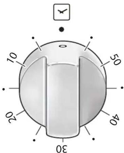
MINUTE COUNTER
The minute counter is a timed acoustic warning device which can be set for a maximum of 60 minutes.
The knob (fig. 5.1) must be rotated clockwise as far as the 60 minute position and then set to the required time by rotating it anticlockwise.
IMPORTANT WARNING: This is only a mechanical timer.
Remember to turn off the oven/grill manually.
text_image
0 10 50 20 40 30Fig. 5.1
GENERAL ADVICE
- Before you begin cleaning, you must ensure that the appliance is switched off.
- When the appliance is not being used, it is advisable to keep the gas tap closed.
- The periodical lubrication of the gas taps must be done only by specialized personnel.
- If a tap becomes stiff, do not force; contact your local After Sales Service Centre.
- It is advisable to clean when the appliance is cold and especially when cleaning the enamelled parts.
- Avoid leaving alkaline or acidic substances (lemon juice, vinegar, etc.) on the surfaces.
- Avoid using cleaning products with a chlorine or acidic base.
- Important: The use of suitable protective clothing/gloves is recommended when handling or cleaning of this appliance.
WARNING
When correctly installed, your product meets all safety requirements laid down for this type of product category. However special care should be taken around the rear or the underneath of the appliance as these areas are not designed or intended to be touched and may contain sharp or rough edges, that may cause injury.
ENAMELLED PARTS
All the enamelled parts must be cleaned with a sponge and soapy water or other non-abrasive products.
Dry preferably with a microfibre or soft cloth.
Acidic substances like lemon juice, tomato sauce, vinegar etc. can damage the enamel if left too long.
STAINLESS STEEL, ALUMINIUM PARTS, PAINTED AND SILK-SCREEN PRINTED SURFACES
Clean using an appropriate product. Always dry thoroughly.
IMPORTANT: These parts must be cleaned very carefully to avoid scratching and abrasion. You are advised to use a soft cloth and neutral soap.
CAUTION: Do not use abrasive substances or non-neutral detergents as these will irreparably damage the surface.
Attention!
The appliance gets very hot, mainly around the cooking areas. It is very important that children are not left alone in the kitchen when you are cooking.
Do not use a steam cleaner because the moisture can get into the appliance thus make it unsafe.
Do not use harsh abrasive cleaners or sharp metal scrapers to clean the oven door glass or the glass lid (models with glass lid only) since they can scratch the surface, which may result in shattering of the glass.
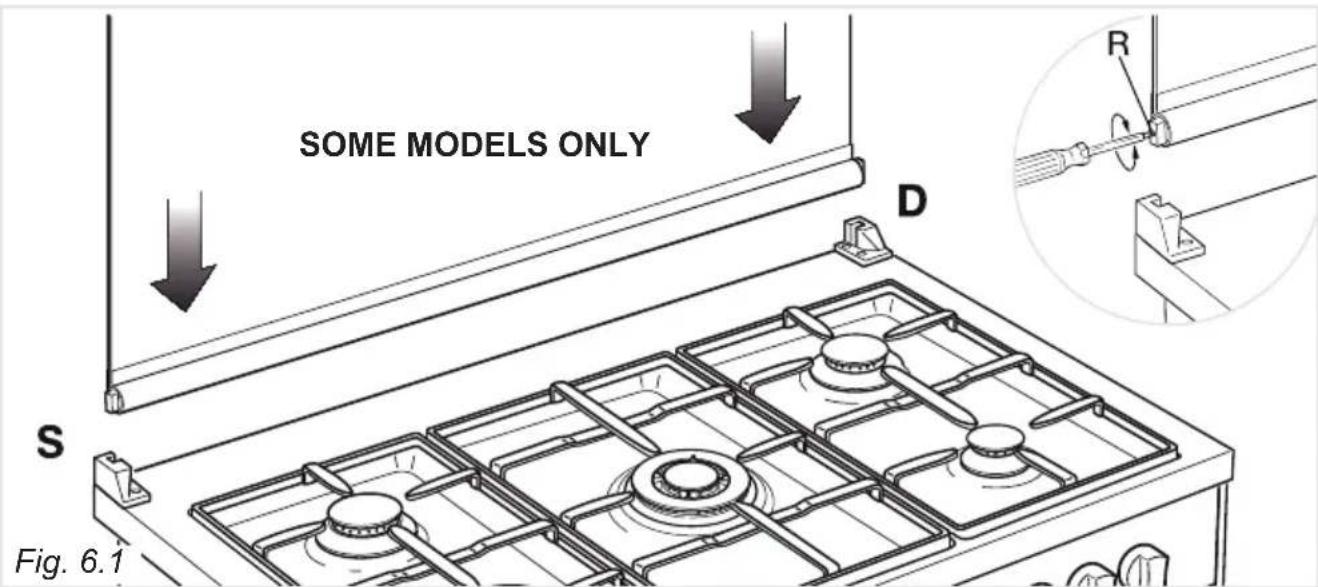
GLASS LID (SUPPLIED WITH SOME MODELS ONLY)
For cleaning purposes, the lid can be easily removed upwards once taken to the upright position.
Should the hinges slip off, replace them in their housing being careful that:
- The right housing must receive the hinge marked "D" while the left housing must receive the hinge marked "S" (fig. 6.1).
REGULATING OF THE BALANCE
Lower the lid and check the correct balance. While opened at 45^ it should hang up.
The springs of the hinges can be adjusted if necessary by turning the screws "R" clockwise (fig. 6.1).
Models with glass lid
natural_image
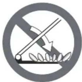
Prohibition sign showing a crossed lever over soil with a downward arrow, enclosed in a circle (no text)Do not shut lid when burner alight.
ATTENTION
√ Do not lower the glass lid when the gas burners are still hot or when the oven is working or still hot.
√ Do not lay on the glass lid hot pans and heavy kitchen utensils.
√ Dry off any liquid whitch may have spilt on the cover before opening it.
text_image
SOME MODELS ONLY D S Fig. 6.1GAS TAPS
Periodic lubrication of the gas taps must be carried out by specialist personnel only. In the event of operating faults in the gas taps, call the Service Department.
INSIDE OF OVEN
The oven should always be cleaned after use when it has cooled down.
The cavity should be cleaned using a mild detergent solution and warm water. Suitable proprietary chemical cleaners may be used after first consulting with the manufacturers recommendations and testing a small sample of the oven cavity. Abrasive cleaning agents or scouring pads/cloths should not be used on the cavity surface.
NOTE: The manufacturers of this appliance will accept no responsibility for damage caused by chemical or abrasive cleaning.
Let the oven cool down and pay special attention no to touch the hot heating elements inside the oven cavity.
Do not store flammable material oven
REPLACING THE OVEN LIGHT BULB
WARNING: Ensure the appliance is switched off before replacing the lamp to avoid the possibility of electric shock.
- Let the oven cavity and the heating elements to cool down.
- Switch off the electrical supply.
- Remove the protective cover.
- Unscrew and replace the bulb with a new one suitable for high temperatures (300°C) having the following specifications: 230V or 220-240V, E14 and same power (check watt power as stamped in the bulb itself) of the replaced bulb
- Refit the protective cover.
Note: Oven bulb replacement is not covered by your guarantee.
BURNERS AND PAN SUPPORTS
These parts can be removed and cleaned with appropriate products.
After cleaning, the burners and their flame spreaders must be well dried and correctly replaced.
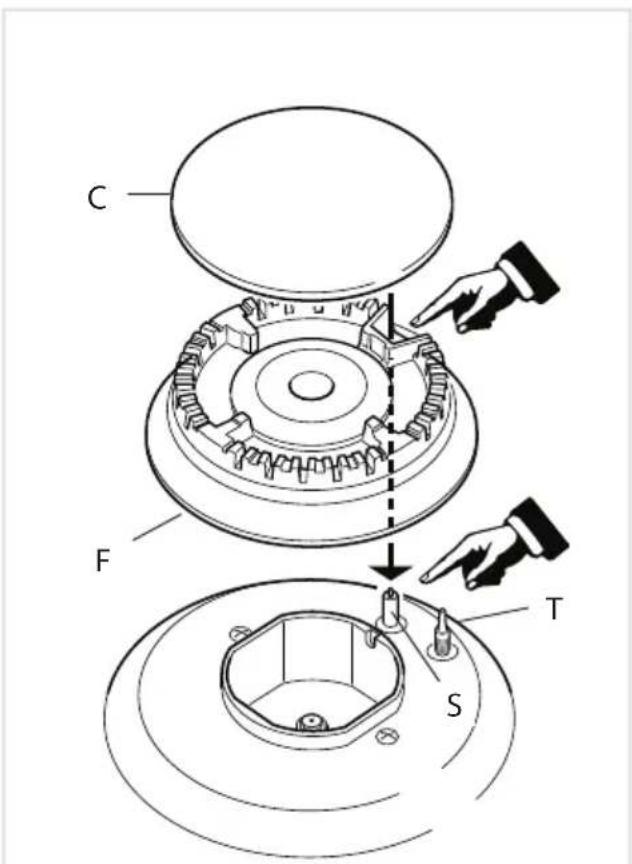
It is very important to check that the burner flame spreader and the cap have been correctly positioned. Failure to do so can cause serious problems.
Check that the electrode "S" (figs. 6.2, 6.4) next to each burner is always clean to ensure trouble-free sparking.
Check that the probe "T" (figs. 6.2, 6.4) next to each burner is always clean to ensure correct operation of the safety valves.
Both the probe and ignition plug must be very carefully cleaned.
Note: To avoid damage to the electric ignition do not use it when the burners are not in place.
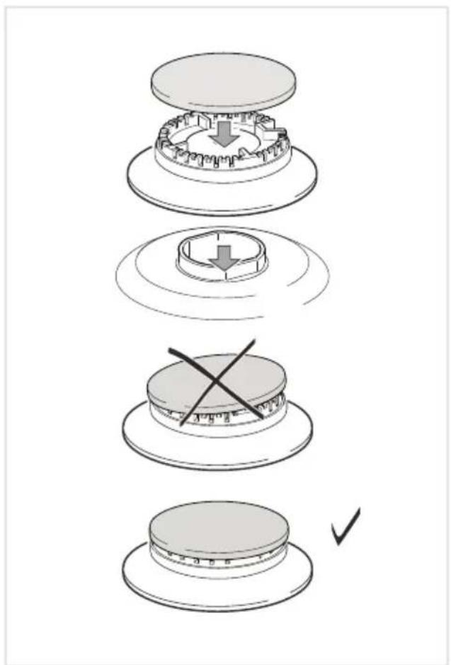
in the CORRECT REPLACEMENT OF THE AUXILIARY, SEMI-RAPID AND RAPID BURNERS
It is very important to check that the burner flame distributor “F” and the cap “C” has been correctly positioned (see figs. 6.2 - 6.3) - failure to do so can cause serious problems.
CORRECT REPLACEMENT OF THE TRIPLE RING BURNER
The triple ring burner must be correctly positioned (see fig. 6.6); the burner rib must be enter in their logement as shown by the arrow (see fig. 6.4).
The burner correctly positioned must not rotate (fig. 6.5).
Then position the cap “A” and the ring “B” (figs. 6.5, 6.6).
text_image
C F T SFig. 6.2 Fig. 6.3
text_image
Diagram illustrating a mechanical assembly process with four steps: press, press, cross-section, and final state.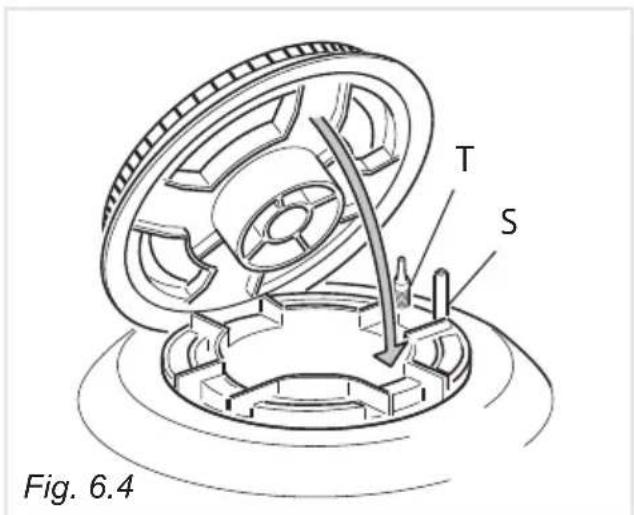
text_image
T S Fig. 6.4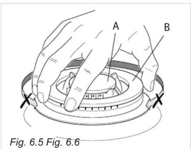
text_image
A B Fig. 6.5 Fig. 6.6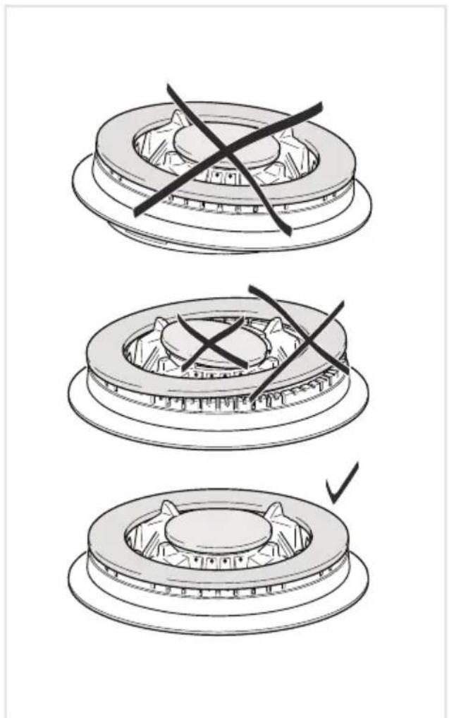
natural_image
Three-step diagram showing a brake disc assembly with cross marks, no text or symbols presentASSEMBLY AND DISMANTLING OF THE SIDE RUNNER FRAMES
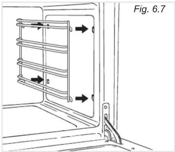
- Fit the side runner frames into the holes on the side walls inside the oven (fig. 6.7). - Slide the rack into the runners (fig. 6.8).
The rack must be fitted so that the safety notch, which stops it sliding out, faces the inside of the oven; the guard rail shall be at the back.
• To dismantle, operate in reverse order.
OVEN TRAY
The oven tray must be correctly placed on its wire support then inserted into the side runners (figs. 6.8, 6.9).
OVEN FLOOR
The oven floor "F" (fig. 6.9) can be easily removed to facilitate cleaning.
Remember to replace the floor correctly afterwards.
Be careful not to confuse the tray "L" with the oven floor "F" (fig. 6.9).
text_image
Fig. 6.7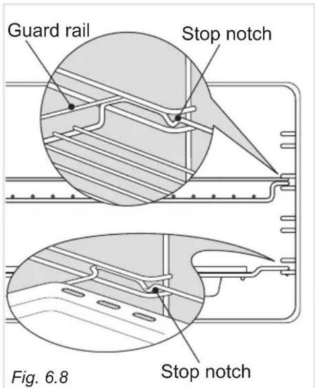
text_image
Guard rail Stop notch Fig. 6.8 Stop notch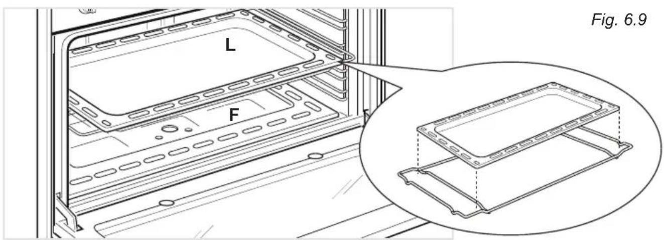
text_image
L F Fig. 6.9STORAGE COMPARTMENT
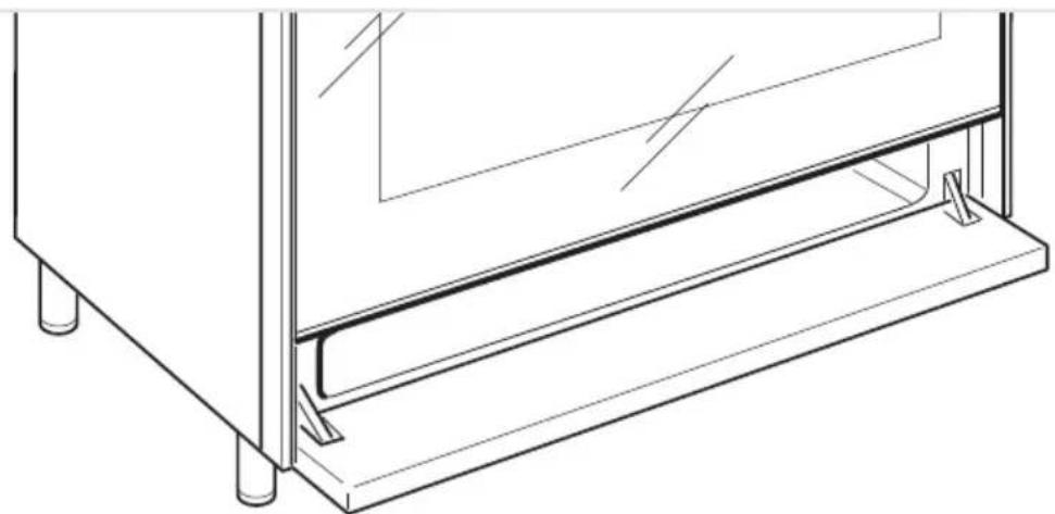
The storage compartment is accessible through the pivoting panel (fig. 6.10).
Do not store flammable material in the oven or in the storage compartment.
natural_image
Technical line drawing of a mechanical assembly with mounting feet and a vertical component (no text or symbols)Fig. 6.10
REMOVING THE OVEN DOORS
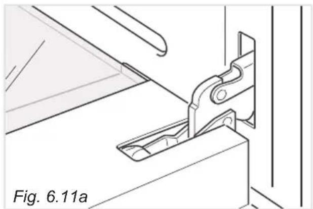
The oven door can easily be removed as follows:
- Open the door to the full extent (fig. 6.11a).
- Open the lever "A" completely on the left and right hinges (fig. 6.11b).
- Hold the door as shown in fig. 6.11d.
- Gently close the door (until left and right hinge levers "A" are hooked to part "B" of the door (figs. 6.11b, 6.11c).
- Withdraw the hinge hooks from their location following arrow "C" (fig. 6.11e).
- Rest the door on a soft surface.
natural_image
Technical line drawing of a mechanical clamp or bracket assembly (no text or symbols)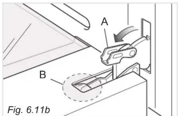
text_image
A B Fig. 6.11b
natural_image
Technical line drawing of a mechanical component or bracket assembly (no text or symbols)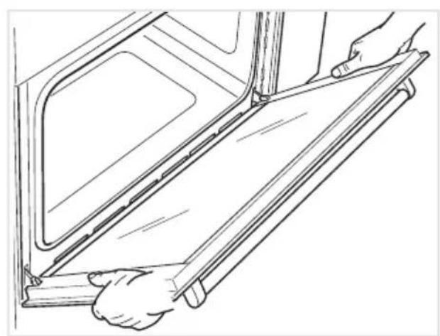
natural_image
Line drawing of hands installing or adjusting a door panel on a vehicle (no text or symbols)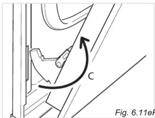
text_image
C Fig. 6.11eFFig. 6.11eFig. 6.11
REFIT THE DOORS
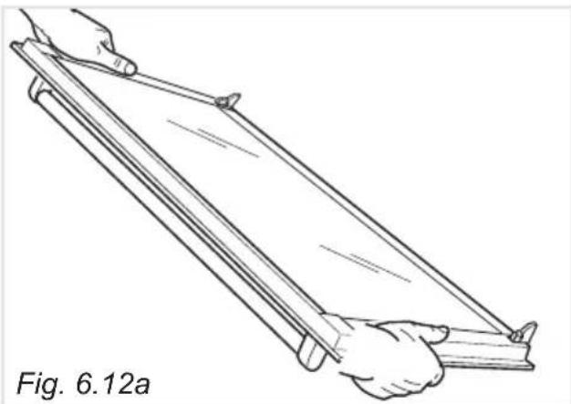
- Hold the door firmly (fig. 6.12a).
- Insert the hinge tongues into the slots, making sure that the groove drops into place as shown in the figure 6.12b.
- Open the door to its full extent.
- Fully close the levers "A" on the left and right hinges, as shown in the figure 6.12c.
- Close the door and check that it is properly in place.
natural_image
Line drawing of two hands holding a long, folded object (no text or symbols)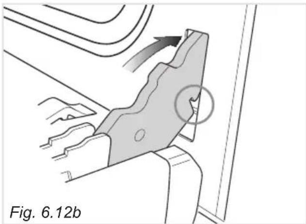
natural_image
Technical diagram of a mechanical component with directional arrows and a circled feature, labeled Fig. 6.12b (no readable text or symbols)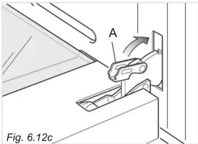
text_image
A Fig. 6.12cREMOVING AND REPLACING THE INNER DOOR GLASS PANE FOR CLEANING
If you wish to clean the inner glass of the door, make sure you follow the precautions and instructions very carefully.
Replacing the glass pane and the door incorrectly may result in damage to the appliance and may void your warranty.
IMPORTANT!
- Make sure the appliance and all its parts have cooled down. Do not attempt to handle the parts of a hot appliance.
• Take extreme care when handling the glass pane. Avoid the edges of the glass bumping against any surface. This may result in the glass shattering. - CAUTION: Do not use harsh abrasive cleaners or sharp metal scrapers to clean the oven door glass since they can scratch the surface, which may result in shattering of the glass.
- If you notice any sign of damage on any of the glass panes (such as chipping, or cracks), do not use the oven. Call your Authorised Service Centre or Customer Care.
- Make sure you replace the glass pane correctly. Do not use the oven without glass pane correctly in place.
- If the glass pane feels difficult to remove or replace, do not force it. Call your Authorised Repairer or Customer Care for help.
Note: Service visits providing assistance with using or maintaining the appliance are not covered by your warranty.
CLEANING THE PANES OF GLASS
The oven door is fitted with no. 2 panes:
- no. 1 outside;
- no. 1 inner.
To clean the panes on both sides it is necessary to remove the inner pane as follows.
REMOVING THE INNER PANE OF GLASS
- Open the door to the full extent (fig. 6.11a).
- Open the lever "A" completely on the left and right hinges (fig. 6.11b).
- Hold the door as shown in fig. 6.11d.
- Gently close the door until left and right hinge levers "A" are hooked to part "B" of the door (figs. 6.11b, 6.11c).
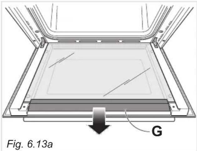
2. Remove the inner pane:
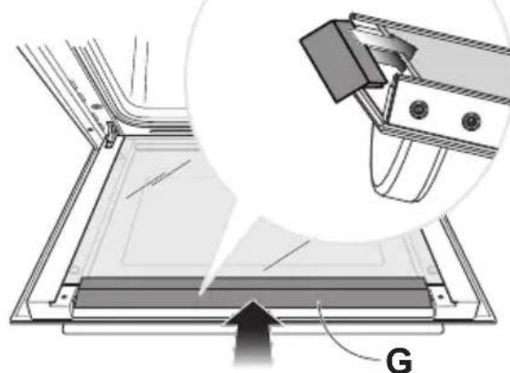
- Gently remove the air deflector "G" at the top of the oven door (fig. 6.13a).
• Gently pull out the inner pane of glass (fig. 6.13b).
IMPORTANT: It is advisable, while removing the glass, to keep pressed in position the four rubber pads "D" (fig. 6.14a), by a finger, to avoid breakage or slippage of the rubber pads themselves.
- Clean the glass with an appropriate cleaner. Dry thoroughly, and place on a soft surface.
Now you can also clean the inside of the outer glass.
text_image
Fig. 6.13a G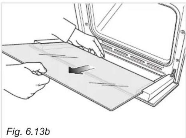
natural_image
Illustration of hands installing or adjusting a flatboard on a vehicle door panel (no text or symbols visible)AFTER CLEANING, REPLACE THE INNER GLASS PANE
When replacing the inner glass pane, make sure that:
- You replace the pane correctly, as shown. The pane must be in the position described below in order to fit into the door and to ensure that the oven operates safely and correctly.
To reassemble the inner pane of the oven door operate as follows:
-
Make sure the door is locked open (see fig. 6.11c).
-
Replace the inner pane:
- Check that the four rubber pads are in place ("D" in fig. 6.14a).
IMPORTANT: It is advisable, while refitting the glass, to keep pressed in position the four rubber pads "D", by a finger, to avoid breakage or slippage of the rubber pads themselves (fig. 6.14b).
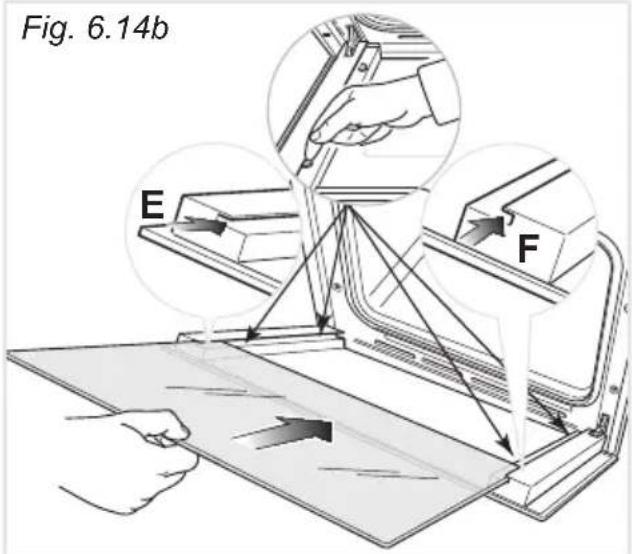
- Check that you are holding the pane the correct way. The shiny side shall face the inside of the oven.
- Insert the pane in the left "E" and right "F" slide guides (fig. 6.14b), and gently slide it to the retainers "H" (fig. 6.14c).
- Gently push the air deflector "G" back into place (fig. 6.14d).
- Unlock the oven door by opening it completely and closing the lever "A" on the left and right hinges (fig.6.14e).
Fig. 6.14d
natural_image
Technical diagram showing a mechanical assembly with a magnified inset of a component (no text or symbols present)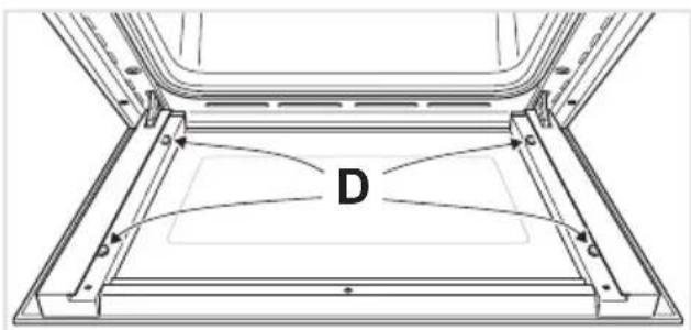
natural_image
Technical line drawing of a mechanical component with labeled point D (no text or symbols beyond label)Fig. 6.14a
text_image
Fig. 6.14b E F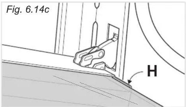
text_image
Fig. 6.14c H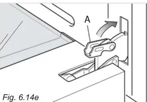
text_image
A Fig. 6.14eAdvice for the installer
IMPORTANT
- Cooker installation must only be carried out by QUALIFIED TECHNICIANS and in compliance with local safety standards. Failure to install the appliance correctly could invalidate any manufacturer's warranty.
- The appliance must be installed in compliance with regulations in force in your country and in observation of the manufacturer's instructions.
- Always disconnect the appliance from the electrical supply before carrying out any maintenance operations or repairs.
- Some appliances are supplied with a protective film on steel and aluminium parts. This film must be removed before using the cooker.
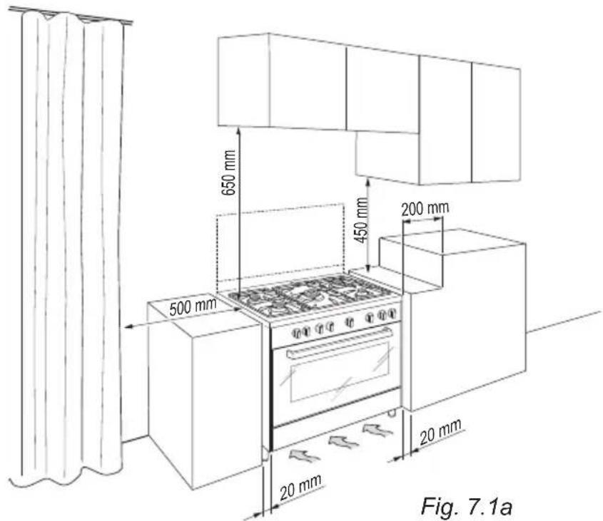
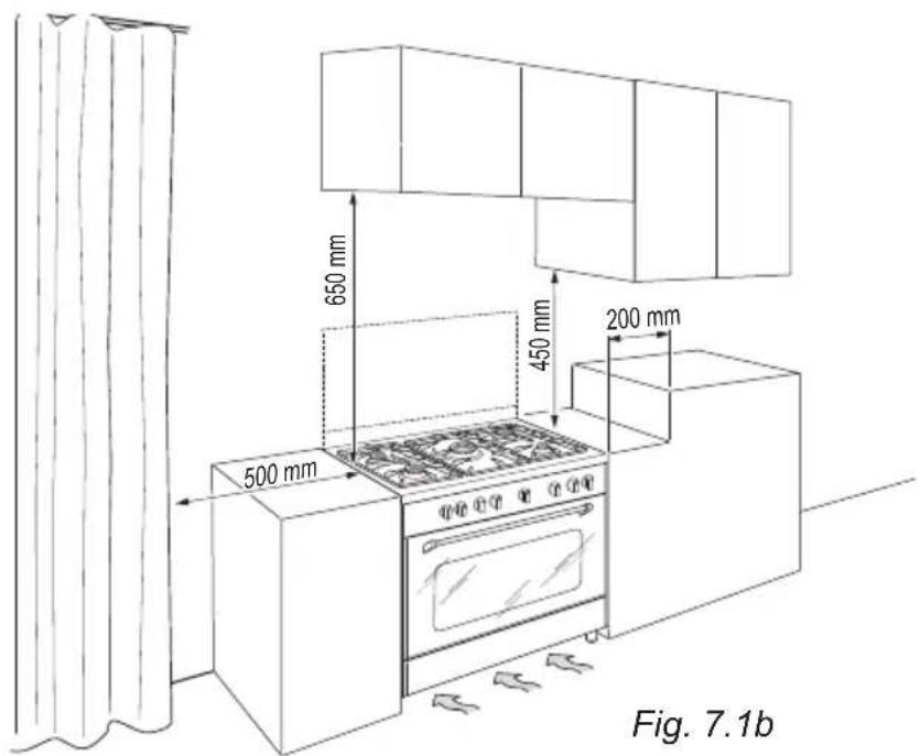
The installation conditions, concerning protection against overheating of the surfaces adjacent to the cooker, must conform to figs. 7.1a or 7.1b.
The cooker must be kept no less than 200 mm away from any side wall which exceed the height of the cooktop.
The veneered syntetical material and the glue used must be resistant to a temperature of 90^ C in order to avoid ungluing or deformations.
Curtains must not be fitted immediately behind appliance or within 500 mm of the sides.
If the cooker is located on a pedestal it is necessary to provide safety measures to prevent falling out.
text_image
650 mm 450 mm 200 mm 500 mm 20 mm 20 mm Fig. 7.1aThe appliance must be housed in heat resistant units.
The walls of the units must not be higher than work top and must be capable of resisting temperatures of 75 °C above room temperature.
Do not install the appliance near inflammable materials (eg. curtains).
■ Class 1
(fig. 7.1a)
Gas connection made using rubber hose which must be visible and easily inspected or using rigid or flexible metal pipe.
text_image
650 mm 450 mm 200 mm 500 mm Fig. 7.1b■ Class 2
■ Subclass 1
(fig. 7.1b)
Gas connection made using rigid or flexible metal pipe.
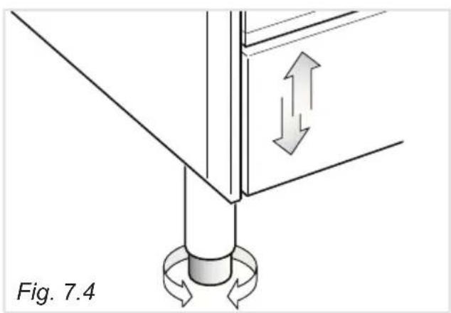
FITTING THE ADJUSTABLE FEET
The adjustable feet must be fitted to the base of the cooker before use (fig. 7.2).
Rest the rear of the cooker on a piece of the polystyrene packaging exposing the base for the fitting of the feet.
Fit the 4 legs by screwing them tight into the support base as shown in figure 7.3.
The cooker may be levelled by screwing the lower ends of the feet IN or OUT (fig. 7.4).
natural_image
Diagram of a mechanical assembly with directional arrows indicating motion, labeled Fig. 7.4 (no text or symbols on the diagram itself)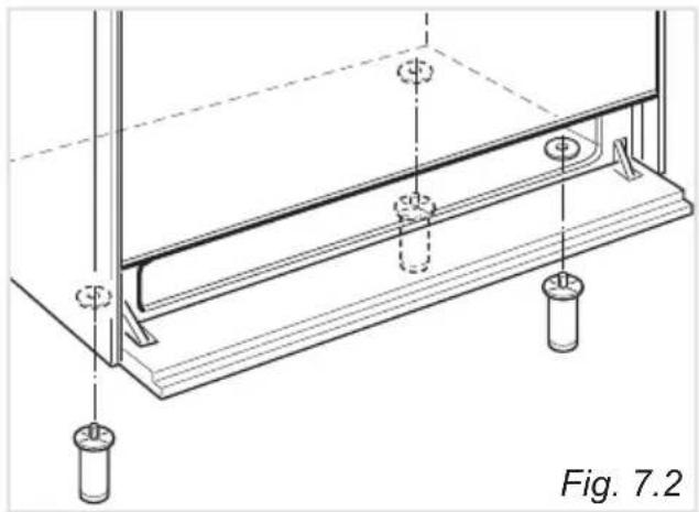
natural_image
Technical line drawing of a structural support frame with mounting holes and supports (no text or symbols)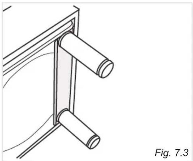
natural_image
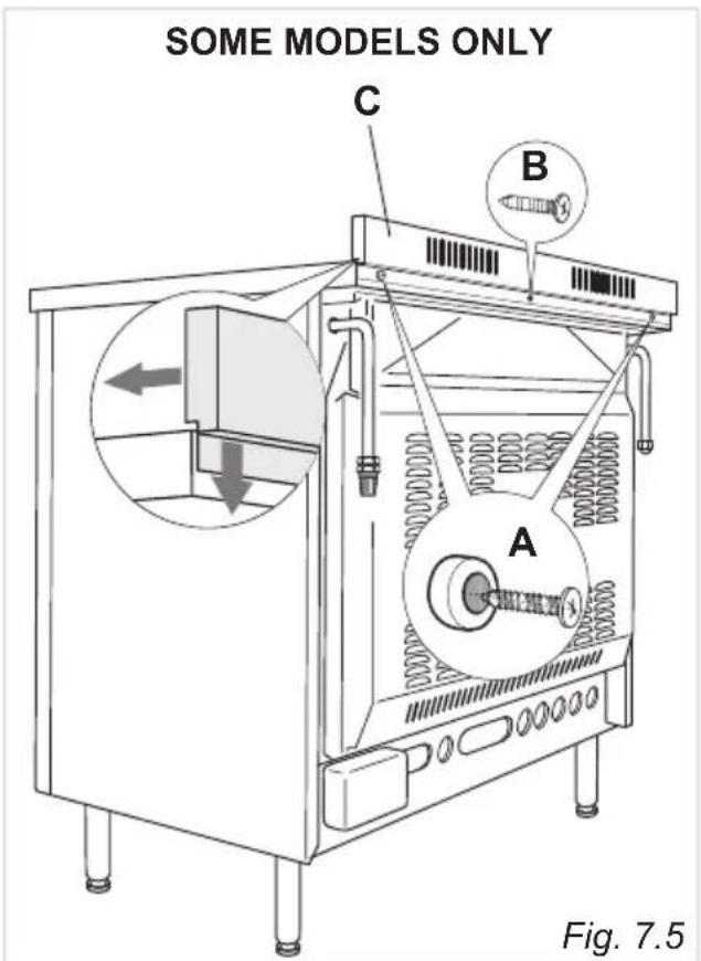
Technical line drawing of a mechanical bracket with two cylindrical components, labeled Fig. 7.3 (no text or symbols on the diagram itself)BACKGUARD (SUPPLIED WITH SOME MODELS ONLY)
Before installing the cooker, assemble the backguard "C" (fig. 7.5).
- The backguard "C" can be found packed at the rear of the cooker.
- Before assembling remove any protective film/adhesive tape.
- Remove the two spacers "A" and the screw "B" from the rear of the cooktop.
- Assemble the backguard as shown in figure 7.5 and fix it by screwing the central screw "B" and the spacers "A".
text_image
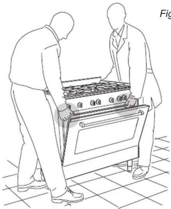
SOME MODELS ONLY C B A Fig. 7.5MOVING THE COOKER
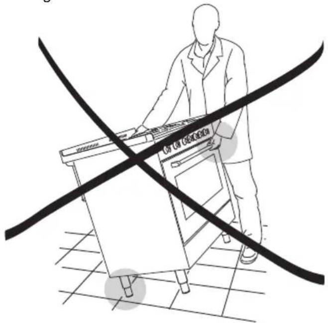
WARNING: When raising cooker to upright position always ensure two people carry out this manoeuvre to prevent damage to the adjustable feet (fig. 7.6).
natural_image
Line drawing of two people inspecting a large outdoor stove on a tiled floor (no text or symbols)Fig. 7.6
WARNING
Be careful: do not lift the cooker by the door handle when raising to the upright position (fig. 7.7).
WARNING
When moving cooker to its final position DO NOT DRAG (fig. 7.8).
Lift feet clear of floor (fig. 7.6).
Fig. 7.7
text_image
CUT LOW CHEMOMICSFig. 7.8
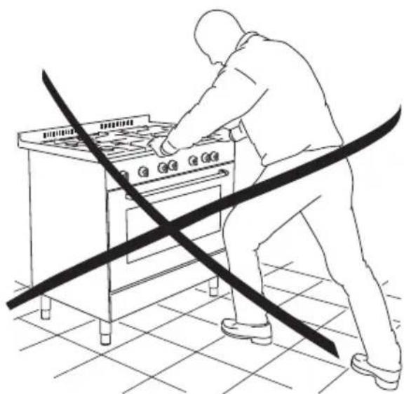
natural_image
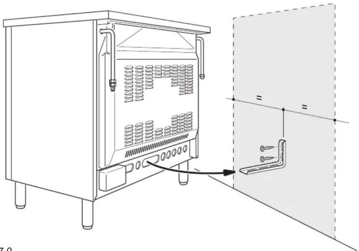
Line drawing of a person using a portable stove with a diagonal line crossing the stove (no text or symbols)ANTI-TILT BRACKET
Important!
To restrain the appliance and prevent it tipping accidentally, fit a bracket to its rear to fix it securely to the wall.
To fit the anti-tilt bracket:
-
After you have located where the cooker is to be positioned, mark on the wall the place where the two screws of the anti-tilt bracket have to be fitted.
Please follow the indications given in fig. 7.9. -
Drill two 8 mm diameter holes in the wall and insert the plastic plugs supplied.
Important!
Before drilling the holes, check that you will not damage any pipes or electrical wires.
-
Loosely attach the anti-tilt bracket with the two screws supplied.
-
Move the cooker to the wall and adjust the height of the anti-tilt bracket so that it can engage in the slot on the cooker's back, as shown in fig. 7.9.
-
Tighten the screws attaching the anti-tilt bracket.
-
Push the cooker against the wall so that the anti-tilt bracket is fully inserted in the slot on the cooker's back.
Attention!
When sliding the cooker into place pay special attention not to trap the power supply cable in the stability bracket.
Pay special attention to the gas connection hose.
natural_image
Technical line drawing of a server rack unit with internal components and a close-up view showing a bracket attachment (no text or symbols)Fig. 7.9
VENTILATION REQUIREMENTS
The appliance must be installed in compliance with applicable local regulations concerning ventilation and the evacuation of exhaust gases.
Intensive and prolonged use may require extra ventilation, e.g. opening a window, or more efficient ventilation increasing the mechanical suction power if this is fitted.
The room where the gas appliance is to be installed must have a natural flow of air so that the gas can burn (in compliance with applicable local regulations).
The flow of air must come directly from one or more openings made in the outside walls with a free area of at least 100 cm^2 (or refer to applicable local regulations).
The openings should be near the floor and preferably on the side opposite the exhaust for combustion products and must be so made that they cannot be blocked from either the outside or the outside.
When these openings cannot be made, the necessary air can come from an adjacent room which is ventilated as required, as long as it is not a bed room or a danger area (in compliance with applicable local regulations).
In this case, the kitchen door must allow the passage of the air.
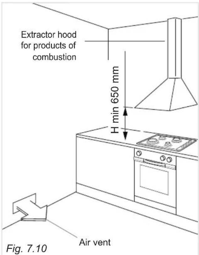
DISCHARGING PRODUCTS OF COMBUSTION
Extractor hoods connected directly to the outside must be provided, to allow the products of combustion of the gas appliance to be discharged (fig. 7.10).
If this is not possible, an electric fan may be used, attached to the external wall or the window; the fan should have a capacity to circulate air at an hourly rate of 3-5 times the total volume of the kitchen (fig. 7.11).
The fan can only be installed if the room has suitable vents to allow air to enter, as described under the heading "Choosing suitable surroundings".
text_image
Extractor hood for products of combustion H min 650 mm Fig. 7.10 Air vent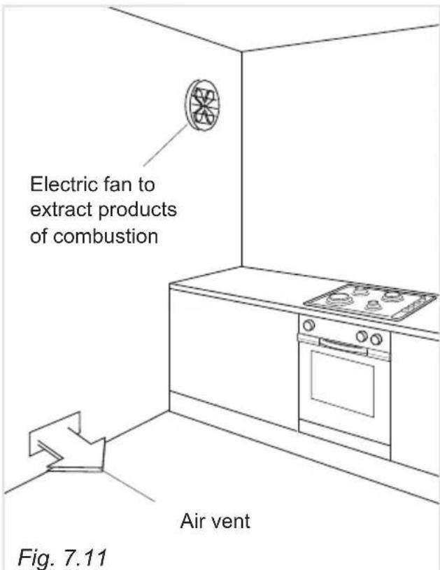
text_image
Electric fan to extract products of combustion Air vent Fig. 7.11GAS INSTALLATION REQUIREMENTS
Important!
- The walls adjacent to the cooker must be of heat-resistant material.
- Before installation, make sure that the local distribution conditions (gas type and pressure) and the adjustment of this appliance are compatible. The appliance adjustment conditions are given on the plate or the label.
- This appliance must be installed and serviced only by a suitably registered installer. The installer shall refer to the local standards in force.
- Failure to install the appliance correctly could invalidate any manufacturer's warranty.
This appliance is supplied for use on Natural gas or LPG (check the gas regulation label attached on the appliance).
- Appliances supplied for use on Natural gas: they are adjusted for this gas only and cannot be used on any other gas (LPG) without modification. The appliances are manufactured for conversion to LPG.
- Appliances supplied for use on LPG: they are adjusted for this gas only and cannot be used on any other gas (Natural gas) without modification. The appliances are manufactured for conversion to Natural gas.
If the Natural gas/LPG conversion kit is not supplied with the appliance this kit can be purchased by contacting the After-Sales Service.
CONNECTING THE APPLIANCE TO THE GAS SUPPLY
The gas connection must be carried out by an authorised person according to the relevant standards.
Ensure that the room in which the cooker is to be installed is adequately ventilated, in compliance with applicable regulations.
- Connect the cooker to the gas mains utilizing rigid or flexible pipes.
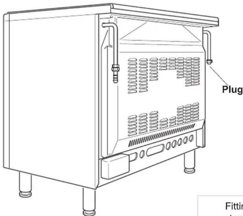
- The gas supply is connected at the rear of the cooker to the right or left terminal of the gas inlet pipe (fig. 8.1). The connection pipe must not cross the rear of the appliance.
- The unused inlet pipe must be closed off with the plug and sealing washer supplied (fig. 8.2).
text_image
Plug FittinFig. 8.1
Fitting the plug on the unused terminal of the gas inlet pipe
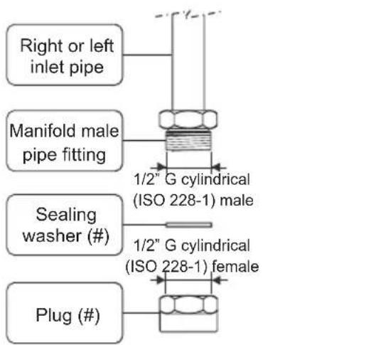
text_image
Right or left inlet pipe Manifold male pipe fitting 1/2" G cylindrical (ISO 228-1) male Sealing washer (#) 1/2" G cylindrical (ISO 228-1) female Plug (#)(#) Already fitted on the right or left inlet pipe
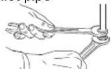
Fig. 8.2
FOR FRANCE ONLY - POSSIBLE GAS CONNECTIONS -
Appliances which cannot be built in (class 1)
For gases supplied by a pipe, the connection can be made using one of the following:
- by fitting the proper hose holder (if not supplied with the appliance it can be purchased by contacting the After-Sales Service), interposing a sealing gasket, and using a suitable flexible hose according to NF D 36-102 with an internal diameter of 15 mm (fig. 8.3c); make sure that the flexible hose is pushed over the hose connector to the full depth, and secured with a hose clamp (not supplied);
(ONLY FOR ALREADY EXISTING GAS INSTALLATIONS)
- a rigid pipe with screw-nut;
- a metal corrugated flexible hose according to NF D 36-121 (fig. 8.4a);
- a flexible hose with mechanical ferrule according to NF D 36-103 or D 36-100 (fig. 8.4b).
For butane-propane distributed by cylinder or tank, the connection is made using one of the following:
• by fitting the proper hose holder (if not supplied with the appliance it can
be purchased by contacting the After-Sales Service), interposing a sealing gasket, and using a suitable flexible hose according to XP D 36-110 with an internal diameter of 6 mm (fig. 8.3d); make sure that the flexible hose is pushed over the hose connector to the full depth, and secured with a hose clamp (not supplied);
(ONLY FOR BUTANE/PROPANE DELIVERED IN MOBILE CONTAINERS OR FOR ALREADY EXISTING GAS INSTALLATIONS)
- a rigid pipe with screw-nut;
- a metal corrugated flexible hose according to NF D 36-125 (fig. 8.4a);
- a flexible hose with mechanical ferrule according to XP D 36-112 (fig. 8.4b).
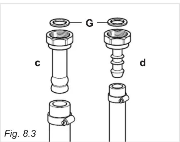
text_image
G c d Fig. 8.3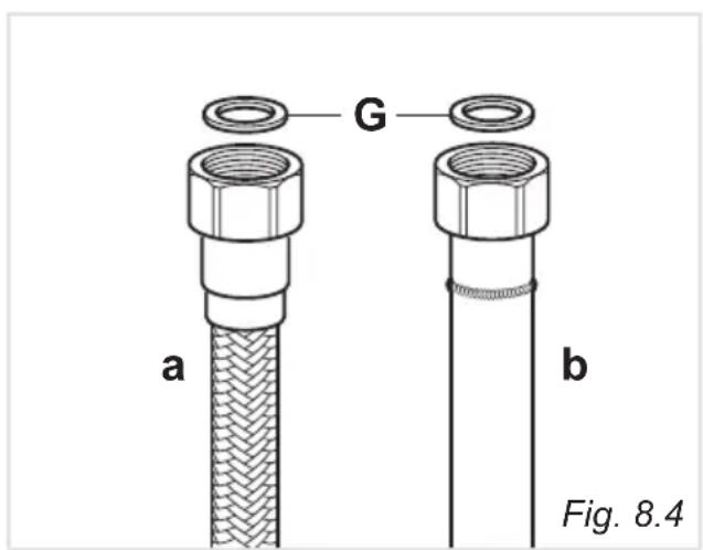
text_image
G a b Fig. 8.4Appliances which can be built in (class 2/1)
For gases supplied by a pipe, the connection can be made using one of the following:
• a rigid pipe with screw-nut;
• a metal corrugated flexible hose according to NF D 36-121 (fig. 8.4a);
- a flexible hose with mechanical ferrule according to NF D 36-103 or D 36-100 (fig. 8.4b).
For butane-propane distributed by cylinder or tank, the connection is made using one of the following:
• a rigid pipe with screw-nut;
• a metal corrugated flexible hose according to NF D 36-125 (fig. 8.4a);
- a flexible hose with mechanical ferrule according to XP D 36-112 (fig. 8.4b).
IMPORTANT:
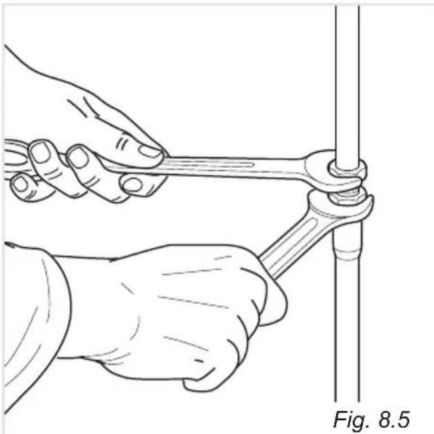
To fix the gas pipe it is necessary to operate with 2 spanners (fig. 8.5).
Access must be possible to the full length of flexible tubes. They must be replaced before their final date of use (marked on the hose) and must be a maximum of 2 m long.
Note: In France, use a tube bearing the mark NF GAZ.
After connecting to the mains, check that the couplings are correctly sealed, using soapy solution, but never a naked flame.
natural_image
Illustration of hands using a wrench to adjust a vertical pipe (no text or symbols present)FOR NON-EUROPEAN UNION COUNTRIES ONLY - POSSIBLE GAS CONNECTIONS -
GAS CONNECTION WITH A RUBBER HOSE
Important!
A rubber hose connection shall only be made if permitted by the applicable local regulations.
The gas connection is made up of:
- the terminal fitting of the inlet pipe (right-hand or left-hand);
- sealing washer;
- the appropriate hose holder (for Natural gas or LPG). If not supplied with the appliance it can be purchased by contacting the After-Sales Service.
Connecting the cooker to Natural gas
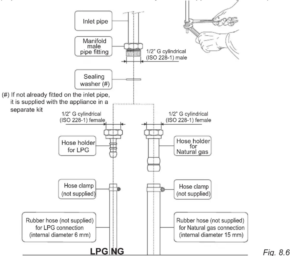
- If not already fitted, fit the Natural gas hose holder on the inlet pipe, making sure that you place the sealing washer between them (as shown in fig. 8.6).
- Connect the cooker to the gas supply using a suitable rubber hose (internal diameter 15 mm).
The hose must comply with the applicable local regulations and be of the correct construction for the type of gas being used. - Make sure that the hose is tightly and securely fitted at both ends.
- Use a standard hose clamp (not supplied) to fasten the hose.
Connecting the cooker to LPG
- If not already fitted, fit the LPG hose holder on the inlet pipe, making sure that you place the sealing washer between them (as shown in fig. 8.6).
- Connect the cooker to the gas supply using a suitable rubber hose (internal diameter 6 mm).
The hose must comply with the applicable local regulations and be of the correct construction for the type of gas being used. - Make sure that the hose is tightly and securely fitted at both ends.
- Use a standard hose clamp (not supplied) to fasten the hose.
- Install a gas pressure regulator.
Important!
To comply with applicable local regulations, a gas pressure regulator (conforming to the local regulations in force) must be installed when connecting the cooker to an LPG cylinder.
When connecting the cooker to the gas supply with a rubber hose, make sure that
• the hose is as short as possible, without twists or kinks.
- the hose is not longer than 750 mm (or refer to applicable local regulations) and does not come into contact with sharp edges, corners or moving parts. Use a single rubber hose only; never connect the appliance with more than one rubber hose.
- the hose is not under tension, twisted, kinked, or too tightly bent, neither while the appliance is in use nor while it is being connected or disconnected.
- the hose does not come into contact with any part of the cooker with a surface temperature of 70^ C or above (or refer to applicable local regulations).
- the hose is not subject to excessive heat by direct exposure to flue products or by contact with hot surfaces.
• the hose can easily be inspected along its entire length to check its condition. - the hose is replaced at the printed due date or if it shows signs of wear or damage, and replaced regardless of its condition after a maximum of three years.
- you inform the customer that the gas cylinder valve or the gas supply valve immediately by the cooker should be closed when the cooker is not in use.
- you inform the customer that the hose should not be subjected to corrosion by acidic cleaning agents.
After connecting the cooker to the gas supply, make sure that you
- check that the connections are correctly sealed using a soapy solution, but never a naked flame.
- check whether the injectors are correct for the type of gas being used. If not, follow the instructions under “GAS MAINTENANCE”.
- replace the sealing washer/s on the slightest sign of deformation or imperfection. The sealing washer/s is/are the part/s which guarantees a good seal in the gas connection.
• use two spanners when fitting the hose holder (fig. 8.6).
Gas connection with rubber hose holders
Note: if not already fitted on the inlet pipe, the hose holders are supplied with the product in a separate kit; if not supplied with the appliance they can be purchased by contacting the After-Sales Service.
(Important: to be used ONLY IF PERMITTED by the local applicable regulations)
text_image
(#) If not already fitted on the inlet pipe, it is supplied with the appliance in a separate kit Inlet pipe Manifold male pipe fitting Sealing washer (#) 1/2" G cylindrical (ISO 228-1) male 1/2" G cylindrical (ISO 228-1) female Hose holder for LPG Hose clamp (not supplied) Rubber hose (not supplied) for LPG connection (internal diameter 6 mm) 1/2" G cylindrical (ISO 228-1) female Hose holder for Natural gas Hose clamp (not supplied) Rubber hose (not supplied) for Natural gas connection (internal diameter 15 mm) LPG NG Fig. 8.6GAS CONNECTION WITH RIGID PIPES OR A FLEXIBLE PIPE
The gas connection is made up of:
- the terminal fitting of the inlet pipe (right-hand or left-hand);
- sealing washer.
Important!
If fitted, remove the hose holder from the terminal fitting of the inlet pipe.
When connecting the cooker to the gas supply with rigid pipes or a flexible pipe, make sure that
- you use rigid pipes or a flexible pipe complying with applicable local regulations. The flexible pipe shall be of the correct construction for the type of gas being used.
- if compression fittings are used, you tighten them firmly using two spanners (fig. 8.7).
- the connection with rigid metal pipes does not cause stress or pressure to the gas piping.
- the flexible pipe is not under tension, twisted, kinked or too tightly bent, neither while the appliance is in use nor while it is being connected or disconnected.
- the flexible pipe does not exceed 2000 mm in length (or refer to applicable local regulations) and does not come into contact with sharp edges, corners or moving parts. Use a single flexible pipe only; never connect the cooker with more than one flexible pipe.
- the flexible pipe can easily be inspected along its entire length to check its condition; if it has an expiry date, it should be replaced before that date.
- if using a flexible pipe which is not entirely made of metal, make sure that it does not come into contact with any part of the cooker with a surface temperature of 70^ or above (or refer to applicable local regulations).
- the hose is not subject to excessive heat by direct exposure to flue products or by contact with hot surfaces.
- the rigid or flexible pipe is replaced if it shows signs of wear or damage.
- a gas pressure regulator, in compliance with the applicable local regulations, is installed when connecting to an LPG cylinder.
- you inform the customer that the cylinder valve or the supply valve immediately by the appliance should be closed when the cooker is not in use.
- you inform the customer that the rigid or flexible pipe should not be subjected to corrosion by acidic cleaning agents.
After connecting the cooker to the gas supply, make sure that you
- check that the connections are correctly sealed using a soapy solution, but never a naked flame.
- check whether the injectors are correct for the type of gas being used. If not, follow the instructions under “GAS MAINTENANCE”.
- replace the sealing washer/s on the slightest sign of deformation or imperfection. The sealing washer/s is/are the part/s which guarantee/s a good seal in the gas connection.
- use two spanners when connecting the rigid or flexible pipe (fig. 8.7).
Gas connection with rigid or flexible pipe
Note: if already fitted on the inlet pipe, remove the rubber hose holder
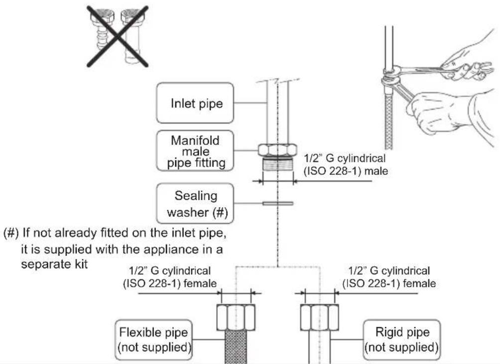
text_image
Inlet pipe Manifold male pipe fitting Sealing washer (#) 1/2" G cylindrical (ISO 228-1) male 1/2" G cylindrical (ISO 228-1) female 1/2" G cylindrical (ISO 228-1) female Flexible pipe (not supplied) Rigid pipe (not supplied) (#) If not already fitted on the inlet pipe, it is supplied with the appliance in a separate kitFig. 8.7
| TABLE FOR THE CHOICE OF THE INJECTORS - Cat: II 2E+ 3+ | ||||||
| BURNERS | Nominal Power [kW] | Reduced Power [kW] | LPGG30 28-30 mbarG31 37 mbar | Natural GasG20 20 mbarG25 25 mbar | ||
| ∅ injector[1/100 mm] | Ring opening[mm] | ∅ injector[1/100 mm] | Ring opening[mm] | |||
| Auxiliary (A) 1,00 | 0,30 50 - | 72 (X) - | ||||
| Semi-rapid (SR) | 1,75 0,45 6 | 5 - 97 (Z) - | ||||
| Rapid (R) 3,00 0, | 75 85 - 115 (Y) - | |||||
| Triple-ring (TR) 3, | 50 1,50 95 - 135 (T) - | |||||
| Oven 6,20 1,20 1 | 20 8 (*) 18 | 0 1,5 (*) | ||||
(*) Reference value
| AIR VENT NECESSARY FOR GAS COMBUSTION = (2 m3/h x kW) | |
| BURNERS | Air necessary for combustion [m3/h] |
| Auxiliary (A) | 2,00 |
| Semi-rapid (SR) | 3,50 |
| Rapid (R) | 6,00 |
| Triple-ring (TR) | 7,00 |
| Oven | 12,40 |
LUBRICATION OF THE GAS TAPS
In case of difficulty in the gas taps operation, call Service.
IMPORTANT
All intervention regarding installation maintenance of the appliance must be fulfilled with original factory parts.
The manufacturer declines any liability resulting from the non-compliance of this obligation.
REPLACEMENT OF THE INJECTORS
If the injectors are not supplied they can be obtained from the "Service Centre".
Select the injectors to be replaced according to the "Table for the choice of the injectors".
The nozzle diameters, expressed in hundredths of a millimetre, are marked on the body of each injector.
REPLACEMENT OF THE INJECTORS OF THE COOKTOP BURNERS
Select the injectors to be replaced according to the "Table for the choice of the injectors".
To replace the injectors proceed as follows:
- Remove pan supports and burners from the cooktop.
- Using a wrench, substitute the nozzle injectors "J" (figs. 8.8a, 8.8b) with those most suitable for the kind of gas for which it is to be used.
The burners are conceived in such a way so as not to require the regulation of the primary air.
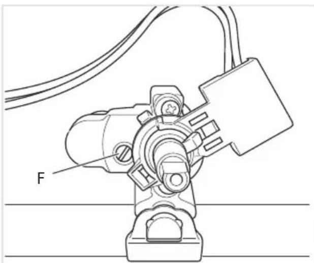
ADJUSTING OF THE MINIMUM OF THE TOP BURNERS
In the minimum position the flame must have a length of about 4 mm and must remain lit even with a quick turn from the maximum position to that of minimum.
The flame adjustment is done in the following way:
- Turn on the burner.
- Turn the tap to the MINIMUM position.
• Take off the knob. - With a thin screwdriver turn the screw "F" until adjustment is correct (fig. 8.9).
N.B. For LPG (G30/G31) the by-pass screw must be fixed thoroughly.
Auxiliary, semi-rapid and rapid burners
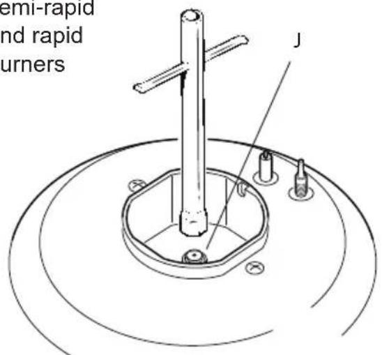
text_image
semi-rapid and rapid burners JFig. 8.8a
Triple-ring
burner
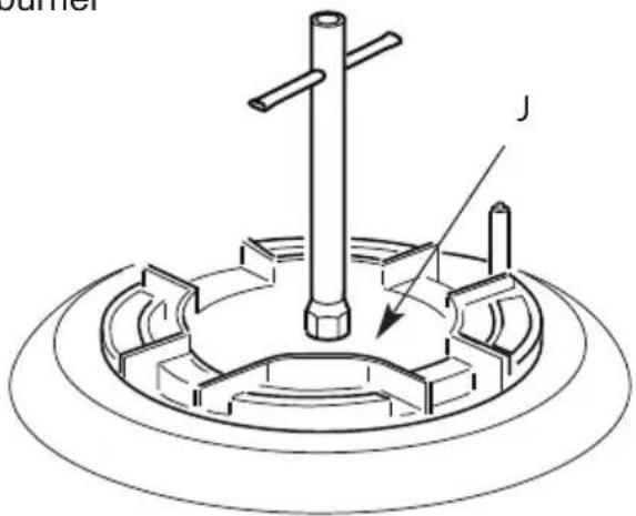
text_image
JFig. 8.8b

natural_image
Technical line drawing of a mechanical assembly with labeled component 'F' (no text or symbols beyond label)Fig. 8.9
OPERATIONS TO BE EXECUTED FOR THE REPLACEMENT OF THE INJECTOR OF THE OVEN BURNER
- Lift and remove the lower panel inside the oven.
- Unscrew and remove the burner securing screw "A" (fig. 8.10).
- Slacken screw "B" (fig. 8.10).
- Withdraw the burner in the manner shown in figure 8.11 and rest it inside the oven. Take care not to damage the wire to the ignition electrode and the safety valve probe.
- Using a 10 mm box spanner, unscrew the injector "U" (indicated by the arrow in fig. 8.11) and replace with a new injector selected in accordance with the "Table for the choice of the injectors"; then replace the burner repeating the above steps in reverse order.
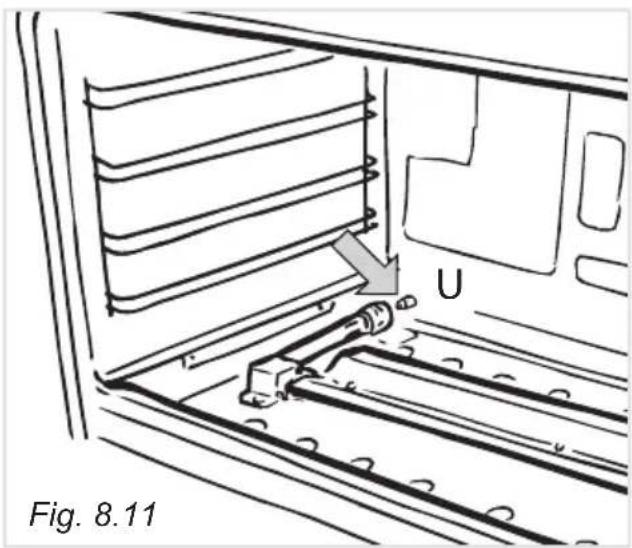
text_image
U Fig. 8.11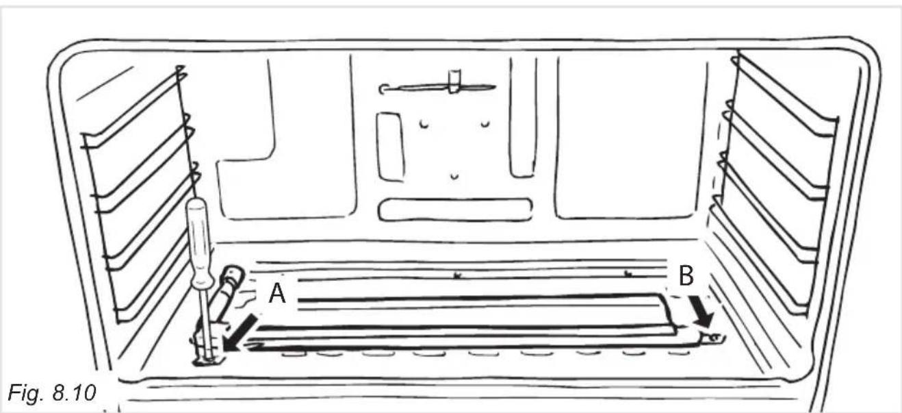
text_image
Fig. 8.10 A B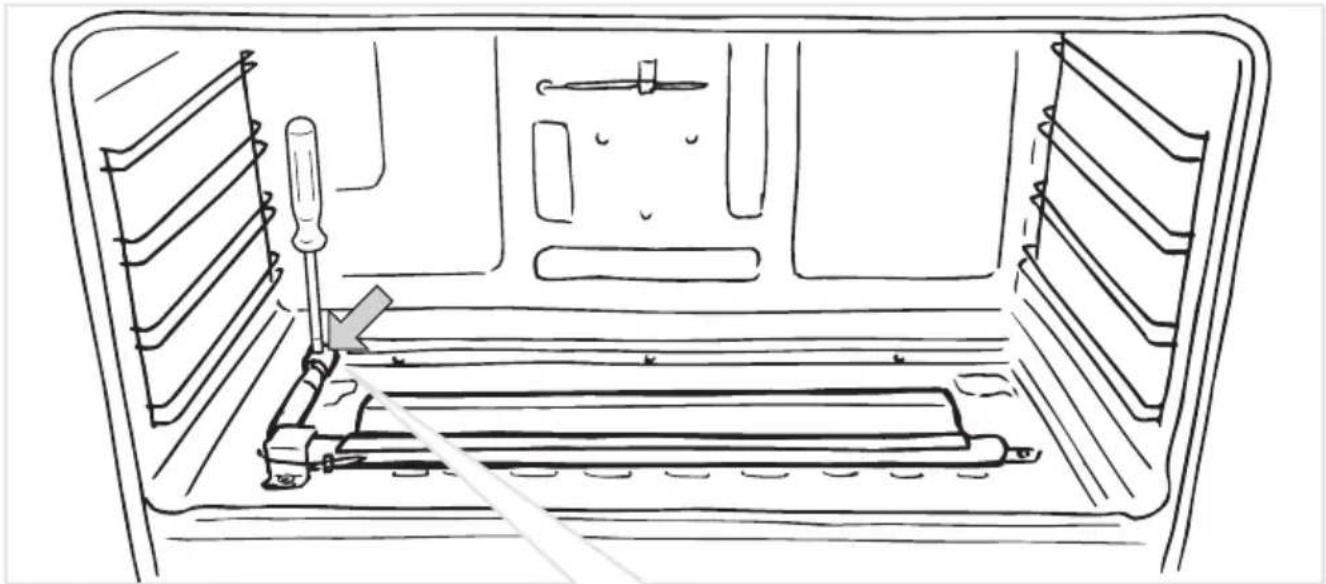
natural_image
Line drawing of a mechanical device with screwdriver and tool, no text or symbols presentFig. 8.12
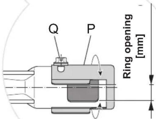
REGULATION OF AIR SUPPLY TO OVEN GRILL BURNER
Using a cross-head screwdriver, slacken the screw “Q” securing the air flow regulation collar “P” (fig. 8.12) and turn the collar forward or backward to increase or reduce the air aperture in accordance with gas type and the indications in the ‘Table for the choice of the injectors’. Light the burner and check the flames.
text_image
Q P Ring opening [mm]| Flame faulty in primary air | Flame correct | Flame with excess primary air |
| long, yellow and trembling | clear interior blue cone | short and sharp too blue interior cone tending to detach |
| CAUSE | ||
| air regulating tube, too closed | correct distance of the tube | air regulating tube, too open |
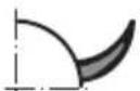
Flame correct
Flame faulty in primary air
Flame with exces s primary air
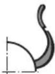
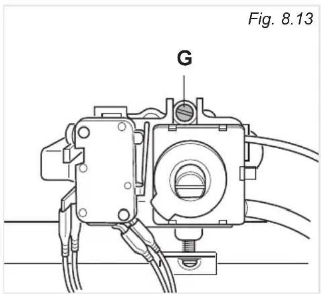
ADJUSTMENT OF THE OVEN BURNER MINIMUM
Considering that in the minimum position the flame must have a length of about 4 mm and must remain lit even with a brusque passage from the maximum position to that of minimum.
The flame adjustment is done in the following way:
- turn on the burner by setting the thermostat knob on position 10 (maximum);
- remove the knob and unscrew the by-pass screw "G" (fig. 8.13) about three times by passing a small flat screwdriver (∅ 3 mm blade, 100 mm length) through the panel opening;
- re-mount the knob and let the oven heat up for about 10 minutes, then bring the knob to position 1 (minimum) to operate the thermostat bypass;
- after having removed the knob again and being very careful not to turn the tap rod, slowly screw the by-pass screws "G" (fig. 8.13) until you obtain a flame of 3 - 4mm in height.
N.B. For G30/G31 (LPG) the by-pass screw must be fixed thoroughly.
text_image
Fig. 8.13 GIMPORTANT: The cooker must be installed in accordance with the manufacturer's instructions.
Incorrect installation, for which the manufacturer accepts no responsibility, may cause damage to persons, animals and things.
GENERAL
- Connection to the mains must be carried out by qualified personnel in accordance with current regulations.
- The appliance must be connected to the mains checking that the voltage corresponds to the value given in the rating plate and that the electrical cable sections can withstand the load specified on the plate.
- The appliance is supplied without a power supply plug and therefore if you are not connecting directly to the mains, a standardized plug suitable for the load must be fitted.
- The plug must be connected to an earthed socket in compliance with safety standards.
- The appliance can be connected directly to the mains placing an omnipolar switch with minimum opening between the contacts of 3 mm between the appliance and the mains.
- The power supply cable must not touch the hot parts and must be positioned so that it does not exceed 75°C at any point.
- Once the appliance has been installed, the switch or socket must always be accessible.
- If the power supply cable is damaged it must be substituted by a suitable cable available in the after sales service.
N.B. For connection to the mains, do not use adapters, reducers or branching devices as they can cause overheating and burning.
If the installation requires alterations to the domestic electrical system or if the socket and appliance plug are incompatible, call an expert.
He should also check that the socket cable section is suitable for the power absorbed by the appliance.
Before effecting any intervention on the electrical parts of the appliance, the connection to the network must be interrupted.
The connection of the appliance to earth is mandatory.
The manufacturer declines all responsibility for any inconvenience resulting from the inobservance of this condition.
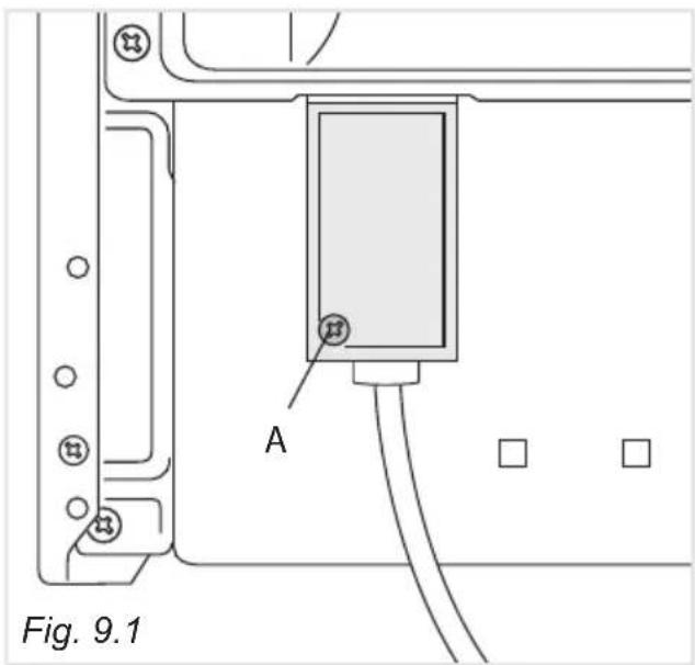
ELECTRICAL FEEDER CABLE CONNECTION
To connect the supply cable:
- Remove the screw securing the cover "A" on the rear of the cooker (fig. 9.1).
- Unscrew cable clamp "D" (fig. 9.2).
- Connect the wires to the terminal block "B" as shown in the diagram in figure 9.3.
- Take up any slack in the cable and secure with the cable clamp "D".
- Replace the cover "A".
text_image
Fig. 9.1 A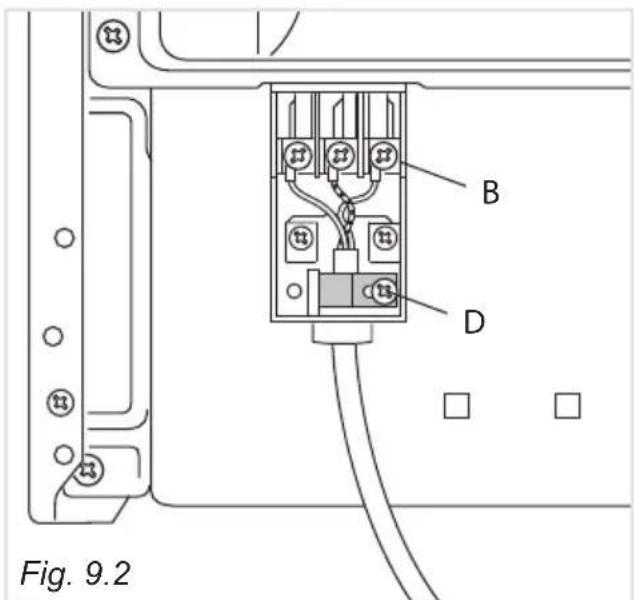
text_image
B D Fig. 9.2FEEDER CABLE SPECIFICATIONS TYPE H05RR-F
230 or 220-240 V\~ 3 x 1,5 mm²(*) (**)
(*) Connection possible with plug and outlet
(**) Connection with wall box connection.
230 or 220-240 V\~
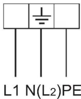
text_image
L1 N(L2)PEFig. 9.3
Cher Client
natural_image
Diagram of a mechanical knob with labeled parts and star indicators (no text or symbols on the knob itself)Attention
natural_image
Diagram of a knob with directional arrows indicating motion, labeled Fig. 3.2 (no text or symbols on the diagram itself)CHOIX DU BRULEUR
natural_image
Line drawing of a cooking pot on a stove (no text or symbols)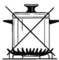
Fig. 3.3
PETITE GRILLE POUR PETIT RECIPIENTS
natural_image
Simple line drawing of a symmetrical mechanical or electrical component (no text or symbols)natural_image
Diagram of a knob with directional arrows indicating rotation, labeled Fig. 4.3 (no text or symbols on the diagram itself)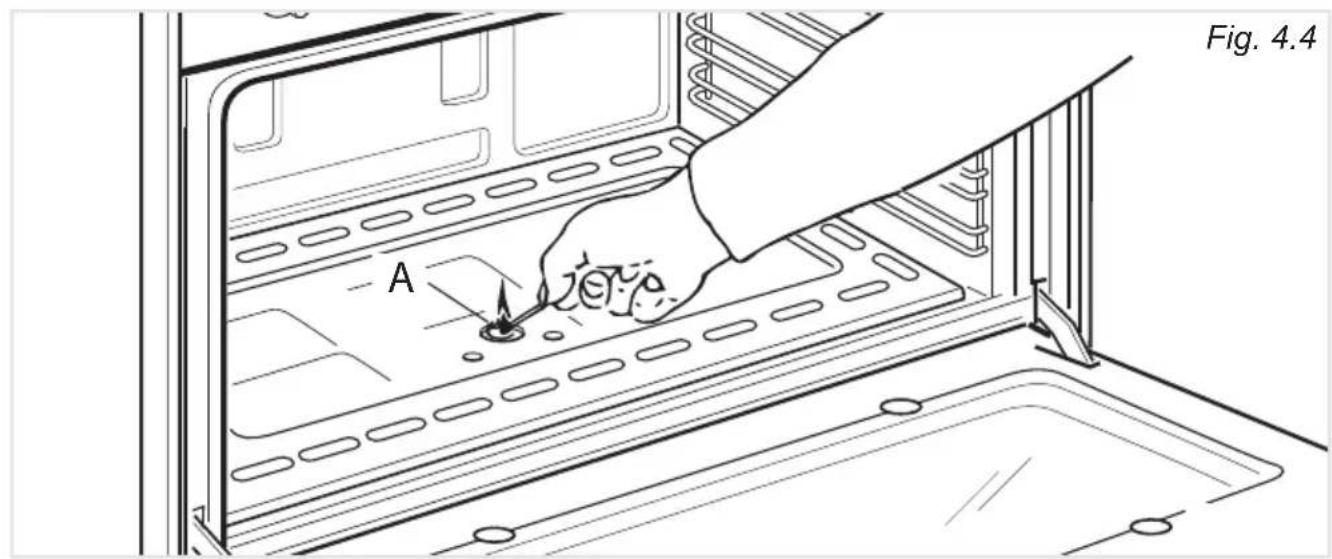
text_image
Fig. 4.4 AGRILLOIR ELECTRIQUE
text_image
Diagram showing a fan dial with a sun icon and a control panel, accompanied by a partial view of the fan.Fig. 4.7
CUISSON AU FOUR A GAZ AVEC VENTILATION

text_image
1 2 3 4 5 6 7 8 9 01 + CONVEREASFig. 4.8
CUISSON AU FOUR A GAZ SANS VENTILATION
text_image
1 2 3 4 5 6 7 8 9 01 Fig. 4-9Fig. 4.9
BRULEUR DU FOUR ET VENTILATEUR
CUISSON AU GRIL AVEC VENTILATION
text_image
Position du maximum Position du minimum Position médiane + SOLVER GASCUISSON AU GRIL SANS VENTILATION
text_image
Position du maximum Position du minimum Position in médianeFig. 4.11 Fig. 4.10
GRIL ELECTRIQUE AVEC VENTILATEUR
natural_image
Prohibition sign depicting a crossed lever mechanism over soil or vegetation, enclosed in a circle (no text or symbols)text_image
Diagram illustrating a mechanical assembly process with four steps: press, press, cross-section, and final state.
text_image
T S Fig. 6.4
text_image
A B Fig. 6.5 Fig. 6.6
natural_image
Three-step diagram showing a brake disc assembly with cross marks, no text or symbols presentMONTAGE ET DEMONTAGE DES CHASSIS LATERAUX
natural_image
Technical line drawing of a mechanical component with spring-loaded housing and mounting bracket (no text or symbols)LECHEFRITE
natural_image
Technical line drawing of a mechanical assembly with mounting feet and a vertical component (no text or symbols)Fig. 6.10
DEMONTAGE DE LA PORTE DU FOUR
natural_image
Technical line drawing of a mechanical clamp or bracket assembly (no text or symbols)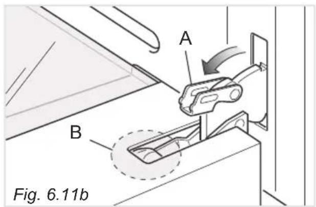
text_image
A B Fig. 6.11b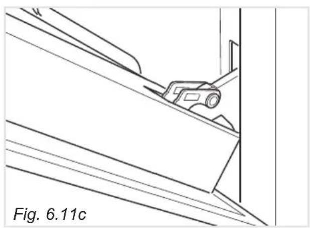
natural_image
Technical line drawing of a mechanical component or bracket assembly (no text or symbols)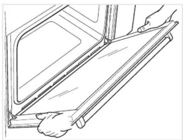
natural_image
Line drawing of hands installing or adjusting a door panel on a cabinet (no text or symbols)
text_image
C Fig. 6.11eFFig. 6.11eFig. 6.11
REMONTAGE DE LA PORTE DU FOUR
natural_image
Line drawing of two hands holding a long, folded object (no text or symbols)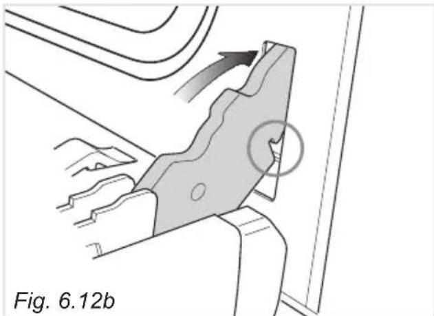
natural_image
Technical diagram of a mechanical component with directional arrows and a circled feature, labeled Fig. 6.12b (no readable text or symbols)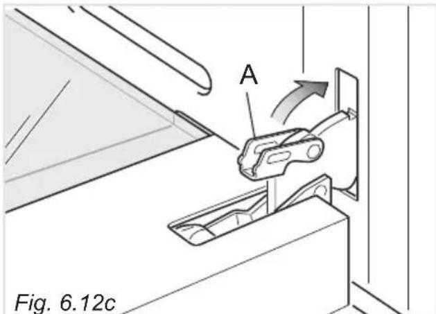
text_image
A Fig. 6.12cMONTAGE ET DEMONTAGE DE LA VITRE INTERIEURE POUR LE NETTOYAGE
natural_image
Illustration of hands installing or adjusting a flatboard inside a vehicle door frame (no text or symbols visible)natural_image
Diagram of a mechanical assembly with directional arrows indicating motion, labeled Fig. 7.4 (no text or symbols on the diagram itself)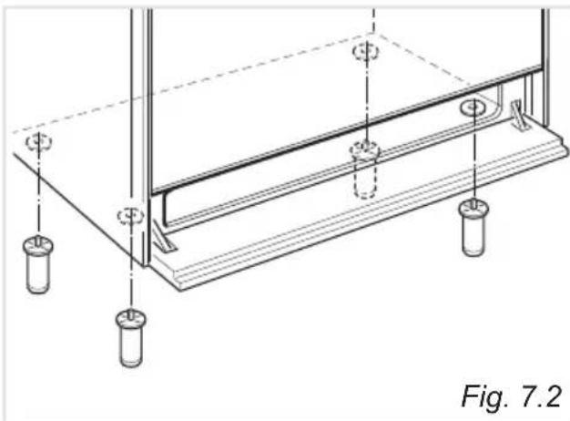
natural_image
Technical line drawing of a structural support frame with mounting holes and supports (no text or symbols)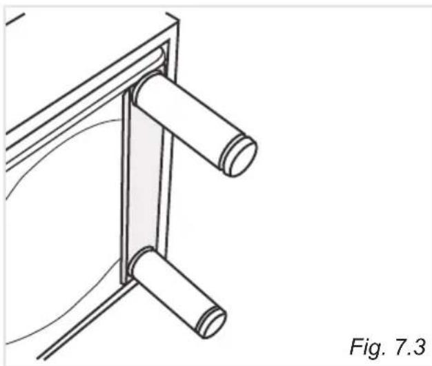
natural_image
Technical line drawing of a mechanical bracket or support structure with two cylindrical components, labeled Fig. 7.3 (no text or symbols on the diagram itself)MONTAGE DU DOSSERET (FOURNI POUR CERTAINS MODELES UNIQUEMENT)
natural_image
Line drawing of two people assembling a large stove on a tiled floor (no text or symbols)Fig. 7.6
AVERTISSEMENT
natural_image
Line drawing of a person using a portable stove with a diagonal line crossing the stove (no text or symbols)ÉQUERRE ANTI-BASCULEMENT
EVACUATION DES PRODUITS DE COMBUSTION
natural_image
Illustration of hands using a wrench to tie a pipe joint (no text or symbols present)SEULEMENT POUR LES PAYS QUI NE SONT PAS DE L'UNION EUROPÉENNE - RACCORDEMENTS GAZ POSSIBLES -
BRANCHEMENT AU GAZ PAR UN TUYAU FLEXIBLE EN CAOUTCHOUC
Important!
text_image
Sourorine JFig. 8.8b
natural_image
Technical line drawing of a mechanical assembly with labeled component 'F' (no text or symbols beyond label)Fig. 8.9
REMPLACEMENT DE L'INJECTEUR DU BRULEUR DU FOUR
natural_image
Line drawing of a mechanical device with screwdriver and tool, no text or symbols presentFig. 8.12