
HCA63420B - Basket BEKO - Free user manual and instructions
Find the device manual for free HCA63420B BEKO in PDF.

| Product Type | Hood |
| Brand | Beko |
| Model | HCA63420B |
| Width | 596 mm |
| Depth | 330 mm |
| Height (adjustable chimney) | 320 to 548 mm |
| Power Supply | 220-240 V ~ 50 Hz |
| Motor Power | 115 W |
| Lighting Power | 6 W (LED) |
| Maximum Airflow | 310 m³/h (3rd speed) |
| Number of Speeds | 3 |
| Control Type | Mechanical (push buttons) |
| Grease Filter | Aluminum, dishwasher safe (every month) |
| Charcoal Filter (optional) | Replace every 3 months (recirculation mode) |
| Exhaust Duct Diameter | 120 or 150 mm |
| Minimum Distance Above Cooktop | 65 cm (gas and electric) |
| Electrical Insulation Class | Class II |
| Included Accessories | Screws, wall plugs, chimney adapter, backdraft damper |
| Repairability Index | Not rated |
Frequently Asked Questions - HCA63420B BEKO
User questions about HCA63420B BEKO
0 question about this device. Answer the ones you know or ask your own.
Ask a new question about this device
Download the instructions for your Basket in PDF format for free! Find your manual HCA63420B - BEKO and take your electronic device back in hand. On this page are published all the documents necessary for the use of your device. HCA63420B by BEKO.
USER MANUAL HCA63420B BEKO
Instructions Booklet
natural_image
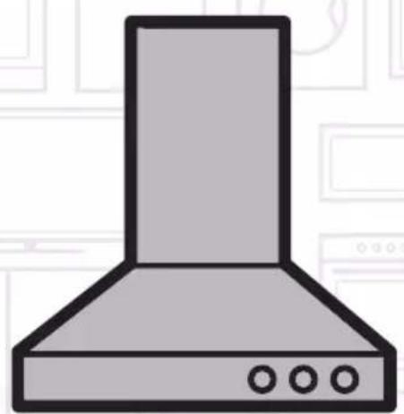
Illustration of a kitchen range hood with three circular buttons (no text or symbols)HCA 62321 B
Please read this user manual first!
Dear Valued Customer,
Thank you for preferring this Beko appliance. We hope that you get the best results from your appliance which has been manufactured with high quality and state-of-the-art technology. For this reason, please read this entire user manual and all other accompanying documents carefully before using the appliance and keep it as a reference for future use. If you handover the appliance to someone else, give the user manual as well. Follow the instructions by paying attention to all the information and warnings in the user manual.
Remember that this user manual may also apply to other models. Differences between models are explicitly described in the manual.
Meanings of the Symbols
Following symbols are used in various sections of this user manual:

Important information and useful hints about usage.

WARNING: Warnings against dangerous situations concerning the security of life and property.

Warning for danger of fire.
Warning for electric shock.

Protection class against electric shock.

This appliance has been manufactured in environmentally friendly modern plants without giving any harm to the nature.
ENGLISH 04-15
POLSKI 16-29
ČESKY 30-42
EESTI 43-55
LIETUVIŲ K 56-68
LATVIJAS 69-81
ROMÂNĂ 82-96
SLOVENSKÝ 97-109
УКРАЇНСЬКИЙ 110-123
FRANÇAIS 124-139
1 Important Safety and Environmental Instructions
1.1 General Safety
Important Safety Instructions Read Carefully And Keep For Future Reference This section contains safety instructions that will help protect from risk of fire, electric shock, exposure to leak microwave energy, personal injury or property damage. Failure to follow these instructions shall void any warranty.
- Beko products comply with the applicable safety standards; therefore, in case of any damage on the appliance or power cable, it should be repaired or replaced by the dealer, service center or a specialist and authorized service alike to avoid any danger. Faulty or unqualified repair work may be dangerous and cause risk to the user.
- This appliance is intended to be used in household and similar applications such as:
- Staff kitchen areas in shops, offices and other working environments;
- Farm houses
- By clients in hotels, and other residential type environments;
- Bed and Breakfast type environments.
- Operate the appliance for its intended purpose only as described in this manual.
- The manufacturer cannot be held liable for damages resulting from improper installation or misuse of the product.
- This appliance can be used by children aged from 8 years and above and persons with reduced physical, sensory or mental capabilities or lack of experience and knowledge if they have been given supervision or instruction concerning use of the appliance in a safe way and understand the hazards involved.
• Children shall not be allowed play with the appliance. Cleaning and user maintenance shall not be made by children without supervision.
- The minimum distance between the supporting surface for the cooking vessels on the hob and the lowest part of your product must be at least 65 cm
- If the instructions for installation for the gas hob specify a greater distance, this has to be taken into account.
• Make sure that your mains power
1 Important Safety and Environmental Instructions
supply complies with the information supplied on the rating plate of the appliance.
- Never use the appliance if the power cable or the appliance itself is damaged.
- Prevent damage to the power cable by not squeezing, bending, or rubbing it on sharp edges. Keep the power cable away from hot surfaces and naked flame.
- Use the appliance with a grounded outlet only.
WARNING: Do not connect the appliance to the mains until the installation is fully complete.
- Place the appliance in a way so that the plug is always accessible.
- Do not touch the lamps if they have operated for a long time. They can burn your hands since they will be hot.
- Follow the regulations set out by competent authorities on discharge of the exhaust air (this warning is not applicable for use without flue).
- Operate your appliance after putting a pot, pan etc. on the hob. Otherwise, high heat may cause deformation in some parts of your product.
- Turn off the hob before taking the pot, pan etc. from it.
- Do not leave hot oil on the hob. Pans with hot oil may cause self combustion.
- Pay attention to your curtains and covers since oil may catch fire while cooking food such as fries.
- Grease filter must be replaced at least monthly. Carbon filter must be replaced at least every 3 months.
- Product shall be cleaned accordance with user manual. If cleaning was not carried out in accordance with user manual, there may be fire risk.
- Do not use non-fire-resistant filtering materials instead of the current filter.
- Only use the original parts or parts recommended by the manufacturer.
- Do not operate the product without the filter and do not remove the filters while the product is running.
- In the event of be started any flame, de-energize your product and cooking appliances.
• In the event of be started any flame, cover the flame and never
1 Important Safety and Environmental Instructions
use water to extinguish.
- Unplug the appliance before each cleaning and when the appliance is not in use.
- The negative pressure in the environment should not exceed 4 Pa (4 x 10 bar) while the hood for electric hob and appliances running on another type of energy but electricity operate simultaneously.
- In the environment where the appliance is being used, the exhaust of devices running on fuel oil or gas, such as room heater must be absolutely isolated or device must be hermetical type.
- When connecting the flue, use pipes with a diameter of 120 or 150 ~mm . Pipe connection must be as short as possible and have as few elbows as possible.
Danger of choking! Keep all the packaging materials away from children.
CAUTION: Accessible parts may become hot when used with cooking appliances.
- The product outlet must not be connected to air channels that include other smoke.
• The ventilation in the room may
be insufficient when the hood for electric hob is used simultaneously with the devices operating on gas or other fuels (this may not apply to appliances that only discharge the air back into the room).
- Objects placed on the product may fall. Do not place any objects on the product.
- Do not flambe under the your product.
WARNING: Before installing the Hood, remove the protective films.
- Never leave high naked flames under the hood when it is in operation
- Deep fat fryers must be continuously monitored during use: overheated oil can burst into flames.
1 Important Safety and Environmental Instructions
1.2 Compliance with the WEEE Directive and Disposing of the Waste Product:
This product complies with EU WEEE Directive
(2012/19/EU). This product bears a classification
symbol for waste electrical and electronic equipment (WEEE).
This symbol indicates that this product shall not be disposed with other household wastes at the end of its service life. Used device must be returned to offical collection point for recycling of electrical and electronic devices. To find these collection systems please contact to your local authorities or retailer where the product was purchased. Each household performs important role in recovering and recycling of old appliance. Appropriate disposal of used appliance helps prevent potential negative consequences for the environment and human health.
1.3 Compliance with RoHS Directive
The product you have purchased complies with EU RoHS Directive (2011/65/EU). It does not contain harmful and prohibited materials specified in the Directive.
1.4 Package Information

Packaging materials of the product are manufactured from recyclable materials in accordance with our National Environment Regulations. Do not dispose of the packaging materials together with the domestic or other wastes. Take them to the packaging material collection points designated by the local authorities.
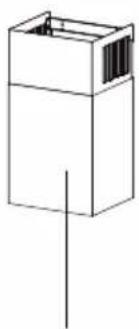
2 General Appearance
2.1 Overview
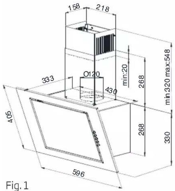
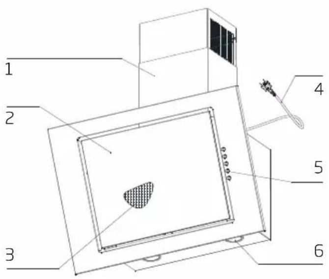
Fig. 2
- Flap
- Chimney Body
- Power Cord
- Aluminum Grease Filter
- Lighting
- Mechanical Control
2.2 Technical Data
| Model | HCA62321B |
| Supply Voltage and Frequency | 220-240 V 50 Hz |
| Lamp Power (W) | 6 W |
| Motor Power (W) | 115 W |
| Air Flow ( m^3/h ) - 3. Level | 310 |
| Motor Insulation Class | Class F |
| Insulation Class | Class II |
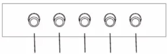
3 Using the Appliance
3.1 Use of the Rocker Switch
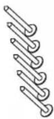
natural_image
Simple diagram of five circular components aligned horizontally with vertical lines below (no text or symbols)Fig.3 1230
The hood is equipped with a mechanical control.
- Pressing the "0" - disables the hood.
- Pressing the "1" - to turn the hood with a minimum speed.
- Pressing the "2" - turns the hood with an average speed.
- Pressing the "3" - turns the hood at maximum speed.
Higher speed means more air flow.
- Press the button - to turn on the lights. Repeat pressing the button to turn off the lighting.
3.2 Things to Do for Energy Saving
- Ensure sufficient air intake to make the hood operate efficiently and with low operation noise during cooking.
- Set the fan level according to the density of steam in kitchen. Use the high level only when needed. A lower fan level means less energy consumption.
- If dense smoke is expected in the kitchen, select a higher level of fan in advance. It is required to operate the hood much longer to remove the smoke already spread all over kitchen.
- Turn off the hood when not in use.
- Clean or replace the filter at intervals stated, thus, the efficiency of the ventilation is increased and the risk of fire is eliminated.
3.3 Operating the Hood
- Hood is equipped with a motor having various
speed settings.
- For a better performance, we advise you to use low speeds in normal conditions, and high speeds when smell and vapors are intensified.
- You can start the hood by pressing the desired speed level key.(1,2,3)
- You can illuminate the cooking area by pressing the light key. (☐)
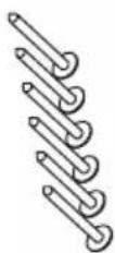
3.4 Lamp Replacement
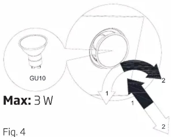
Fig. 4
Symbol → Bulb installation
Symbol → Bulb dismantling
Disconnect the hood from the mains supply. This appliance is equipped with 3 W spot LED lamps.

Before replacing the light bulbs, disconnect the power supply of the hood.

Do not touch the light bulbs when they are hot.

Be careful not to touch the replaced light bulb directly with hands.

You may procure lamps from Authorised Service Agents.
4 Cleaning and Maintenance
Prior to cleaning and maintenance, unplug the appliance or turn the main switch off or loosen the fuse that supplies the hood.

Failure to comply with the provisions relating to cleaning of the device and replacement of filters may cause fire risks. It is therefore recommended to comply with the guidelines given herein. The manufacturer is not liable for any damage to the engine or fires caused by improper use.
Clean using only a cloth dampened with neutral liquid detergent. Do not clean with tools or instruments. Do not use abrasive products. Do not use alcohol
4.1 Cleaning of Aluminium Grease Filter
This filter captures oil particles in the air. You are recommended to clean your filter every month under normal usage conditions. First remove the grease filters for this process. Wash the filters with liquid detergent and rinse them with water and install them back after they get dry. Aluminium grease filters may get discolored as they are washed; this is normal and you don't need to change your filter.
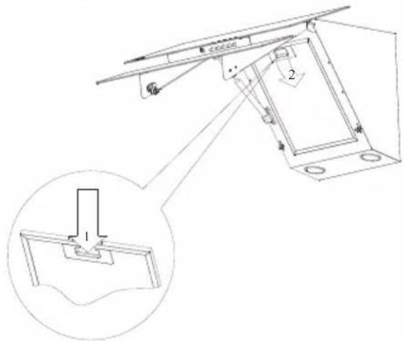
Fig. 5

You can wash the grease filter in the dishwasher
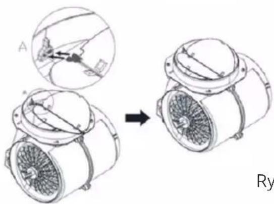
4.2 Changing of Carbon Filter (Air Circulation Mode)
The hood can be fitted with an active carbon filter. The carbon filter is applied only in case the hood is not connected to the vent duct.
In any case it is necessary to replace the carbon filter at least every three months.
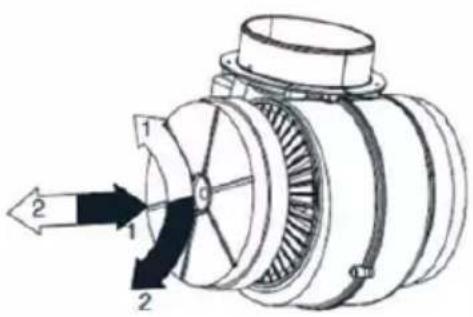
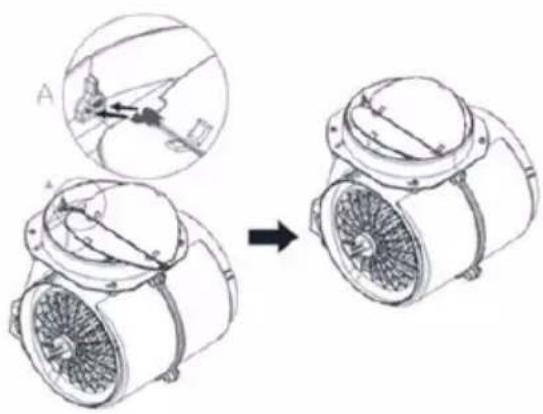
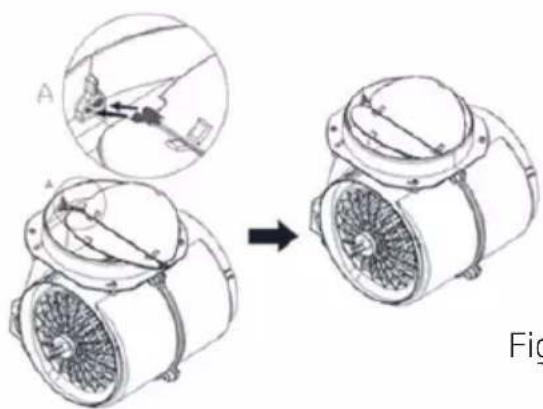
Fig. 6
natural_image
Diagram showing a mechanical assembly before and after transformation, with no visible text or symbols.Fig. 7
WARNING: The carbon filter is never washed.

WARNING: Carbon filter is available from Authorized Services.
5 Setting Up the Device

WARNING
Please read saffety instructions before setting up.

WARNING
Failure to install the screws or fixing device in accordance with these instructions may result in electrical hazards.
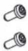
5.1 Installation Accessories
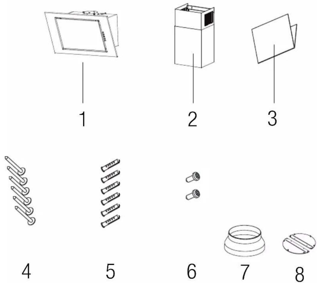
Fig. 8
1 - Hood
2- Chimney
3- User Manual
4- 4 x ∅ 5 x 45 Screw
5- 6 x ∅ 8 x 40 Screw Plug
6-2 x ∅ 3,9 x 9,5 Screw
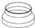
7- ∅150/120mm Plastic Flue Adapter
8- Back Pressure Valve
5 Setting Up the Device
5.2 Hood installation
The use of screws and fastening elements not specified in the Operation Manual may cause the electrical shock.
The minimum distance of hood hanging between the surface of kitchenware placement over the cooking range (gas, electric range), and lowest part of the hood (Fig.3) shall amount at least 65 cm for electric cooking ranges and at least 65 cm for gas cooking ranges. Should the cooking range operation manual provide the higher distance for hood installation, such higher distance requirement shall be maintained. The installation of the hood and chimney body is shown at the figures (Fig.4 - Fig.9). The hood is equipped with the fixing pins matching to the most part of walls and ceilings. In course of the assembly, observe the common rules for air exhaust from the premises.
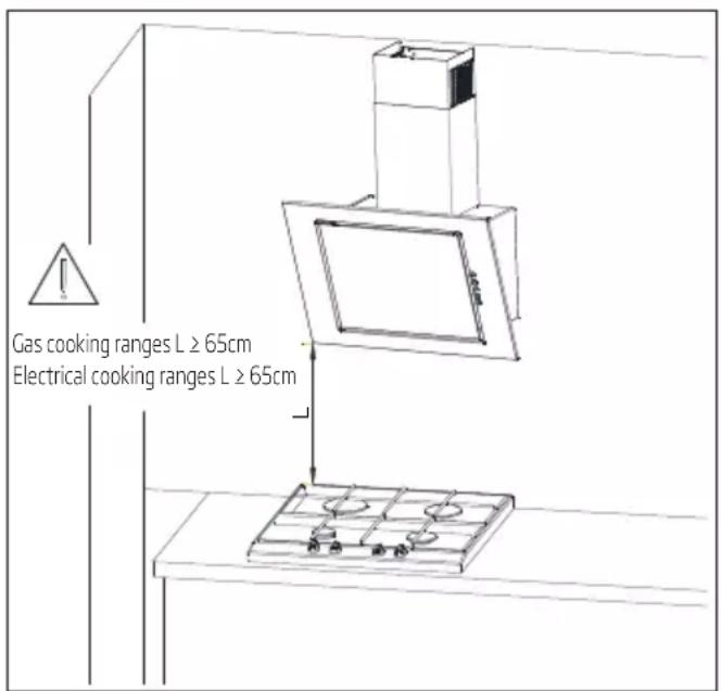
Fig.9 Recommended distances from the cooking range
Before starting the installation:
- Check if the purchased device dimensions match to the planned installation place.
- Disassembly and remove (if possible) any furniture remaining in the hood installation area, in order to ensure the easy access to ceiling or wall, where the hood shall be mounted. If it is not possible, protect the furniture elements remaining in the adjacent area.
- Check, if there is a socket near the mounting area, and control if the hood may be connected to the ventilation channel for vapours evacuation.
- Check if there are no cables (electrical, hydraulic, etc.) in places in which the drilling will be performed.
- Prepare the following tools: tape ruler, pencil, drill / electric screwdriver, drilling tool ∅8, screwdriver, builder's level.
Assembly operation:
- Define the axis of cooking range, and project it onto the wall, where the hood will be mounted. Sign all characteristic points of hood fastening. Make the openings with the drill. (Fig. 10)
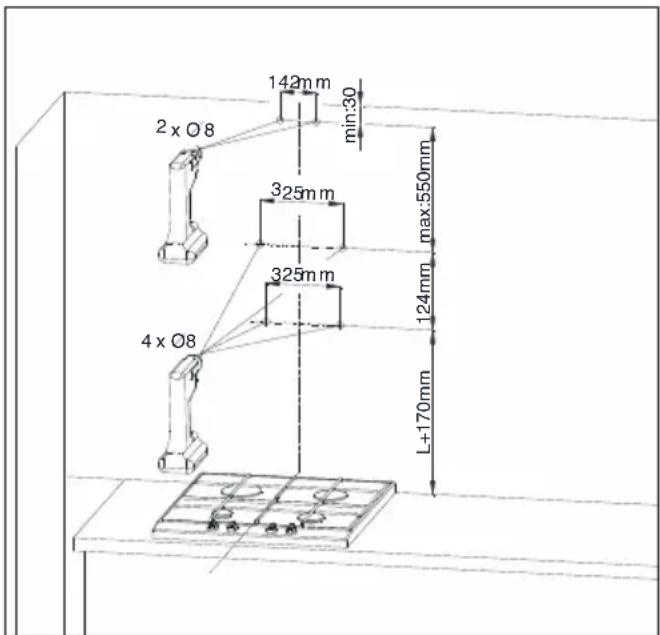
Fig.10 Assembly dimensions
- Into the openings, insert the screw plugs. In two openings marked with A screw also the screws
5 Setting Up the Device
(leaving 7 mm of screw length outside the screw plug, Fig.11).
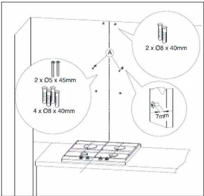
Fig.11 Screw plugs assembly
- Screw the chimney body fastening element, hang the hood on two untightened screws (Fig. 12).
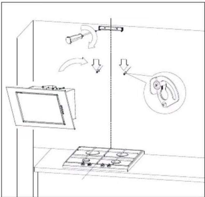
Fig.12 Hood hanging
- Open the hood cover and remove the fat filter (Fig.13).
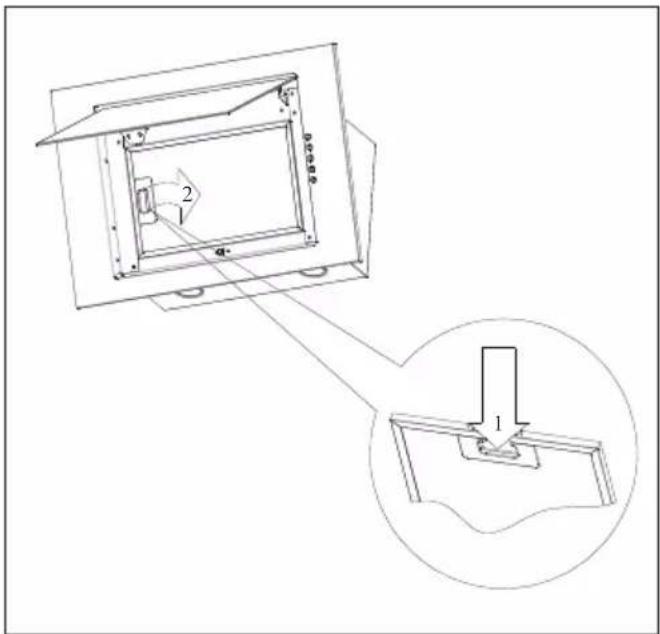
Fig.13 Aluminium fat filter removing
- Place the level on the hood body. Rotating the element marked with A, adjust the hood level according to the level's indications, and then tighten two screws previously screwed partially and screw in two remaining screws (Fig. 14).
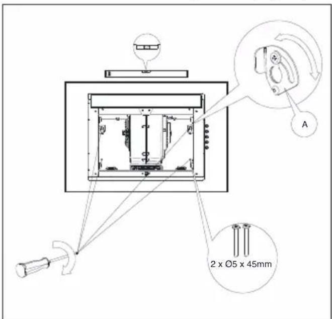
Fig.14 Range hood positioning
5 Setting Up the Device
Place the chimney body on the hood body. Then, draw delicately the hood part signed with B upwards, until it becomes possible to screw it to the fastening element previously attached to the wall (Fig. 15).
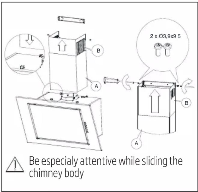
Fig.15 Chimney body assembly

This assembly operation shall be performed very carefully, in order to avoid the scratching of chimney body and hood itself.
5.3 Electrical connections
The network voltage shall correspond to the voltage indicated at the plate placed inside the hood. If the hood is equipped with a plug, insert it into the socket complying with the applicable requirements, and located in the easily accessible place. If the hood is not equipped with a plug, the hood installations shall be performed by a person having the required authorizations (such as electrician).
6 Troubleshooting
| Symptoms Cause | Repairing method | |
| During hood operation, the pulsating letter „F” is displayed. | After 35 hours of operation the hood indicates the need for cleaning or replacing the grease filter. | Press and hold for about 8 sec. "-" on the touch control. The filter should be washed in the dishwasher or replace with a new one. |
| The display shows only the symbol “-.” (minus and dot in the right bottom corner), the hood does not respond to disabling. | The touch control has been locked - this feature facilitates the hood cleaning. | To disable the lock, press and hold for about 10 sec the field with the symbol of switching on. |
| No symbol is shown on the display, the hood does not respond to pressing the control fields. | The touch control is probably suspended. | Disconnect the hood from the power supply for about 15 sec. and switch it on again. |
| The display shows the symbol of one of the gears; the hood does not respond to pressing the control fields. | The touch control is probably suspended | Disconnect the hood from the power supply for about 15 sec. and switch it on again. |
| The hood turbine disconnects after 15 min of operation, the display shows a pulsating digit i.e. "1." (current gear number and dot in the right bottom corner). | The automatic time switch of the touch control has been activated. | To deactivate the time switch, press and hold for about 10 sec the symbol „+”or disable the hood. |
| On fourth gear the digit "4" is pulsating on the display, after 5min the gear is changed into third. | The hood is equipped with a turbo mode, which automatically switches over into third gear after 5 min of operation to save energy. | The turbo gear shall be used only with intensive cooking. |
| The hood can be operated only with use of the control panel, it does not respond to the remote control. | The battery of the remote control is empty or the distance is too long. | Replace the battery with a new one. |
| The hood has very poor vapor suction. | Probably cause is dirty filters. | The grease filter must be cleaned in the dishwasher or replace with a new one. The carbon filter (if present) must be replaced with a new one. |
| One or more light points do not operate. | Defective halogen/ LED bulb. The light | bulb needs to be replaced with a new, compatible with the symbol specified in the instruction manual for the cooker hood. |
| The hood generated excessive noise and vibration. | This may be caused by an incorrect installation of the hood to the wall or kitchen cabinets. Not all provided screws have been used or screws are loosely fitted leaving clearance. | The hood must be mounted to a wall or cabinet by using all the points provided for by the manufacturer. After adjusting the position of the hood horizontally and vertically, tighten all mounting screws. |
| * applies to hoods with touch control. | ||
| If the recommendations above do not solve the problem, contact an authorized home appliances service entitled to repair. Under no circumstances is the hood user entitled to independent repair. A list of service points is included in the warranty card and the website. | ||
Bulb installation Bulb dismantling
Rys. 6
natural_image
Diagram of a mechanical device with two views (A and Ry) showing internal components before and after assembly, no text or symbols present.Rys. 7
natural_image
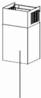
Simple line drawing of a rectangular frame with rounded corners and a small inset showing dimension 'A' (no text or symbols)
1
natural_image
Simple line drawing of a rectangular box with a vertical line extending from its top (no text or symbols)2
natural_image
Simple line drawing of two overlapping rectangles with a vertical line crossing through them (no text or symbols)3
4
5
Rys. 8
6
7
8
Joonis 6 Ôhupuhasti riputamine
Joonis 10 Söefiltri vahetamine
10 pav. Anglies filtro pakeitimas
- att. Ogles filtra maina
Fig. 5 Montarea diblurilor
Fig. 6 Suspendarea hotei
Fig. 8 Pozitionarea hotei
4 Instalare
Obr. 6 Zavesenie digestora
Obr. 8 Polohovanie rozsahu digestora
4 Inštalácia
Fig. 5

Fig. 6
natural_image
Diagram showing a mechanical assembly before and after transformation, with no visible text or symbols.Fig. 7
natural_image
Simple line drawing of a rectangular frame with a vertical line at the bottom (no text or symbols)1
natural_image
Simple line drawing of a rectangular box with a vertical line extending from its top (no text or symbols)2

natural_image
Simple line drawing of two overlapping rectangles with a vertical line crossing through them (no text or symbols)3
4
5

6
7
8
1- Hotte
2-Cheminée
Fig.12 Suspension du capot