VXP 12 - Speaker TANNOY - Free user manual and instructions
Find the device manual for free VXP 12 TANNOY in PDF.

User questions about VXP 12 TANNOY
0 question about this device. Answer the ones you know or ask your own.
Ask a new question about this device
Download the instructions for your Speaker in PDF format for free! Find your manual VXP 12 - TANNOY and take your electronic device back in hand. On this page are published all the documents necessary for the use of your device. VXP 12 by TANNOY.
USER MANUAL VXP 12 TANNOY
natural_image
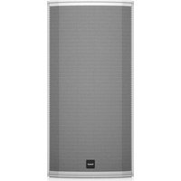
Four black TANOC audio speakers standing upright, no visible text or symbols on the devices themselves.VXP Series
VXP 15HP (-WH)
1600 Watt 15" PowerDual Powered Sound Reinforcement Loudspeaker with
Integrated LAB GRUPPEN IDEEA Class-D Amplification
VXP 12 (-WH)/VXP 8 (-WH)/VXP 6 (-WH)
1600 Watt 12"/8"/6" Dual Concentric Powered Sound Reinforcement Loudspeaker with
Integrated LAB GRUPPEN IDEEA Class-D Amplification
2 VXP Series Quick Start Guide 3
EN
ES
EN Important Safety Instructions
Terminals marked with this symbol carry electrical current of sufficient magnitude to constitute risk of electric shock. the only high quality professional speaker tables with 15" TS or twist-locking plugs pre installed. All other installation or modification should be performed only by qualified personnel.
This symbol, wherever it appears, alerts you to the presence of uninsulated dangerous voltage inside the enclosure - voltage that may be sufficient to constitute a risk of shock.
This symbol, wherever it appears, alerts you to important operating and maintenance instructions in the accompanying literature. Please read the manual.
Caution To reduce the risk of electric shock, do not remove the top cover (or the rear section). No user serviceable parts include. Refer servicing to qualified personnel.
Caution To reduce the risk of fire or electric shock, do not expose this appliance to rain and moisture. The apparatus shall not be exposed to dripping or splashing liquids and no objects filled with liquids, such as wares, shall be plated on the apparatus.
Caution These service instructions are for use by qualified service personnel only. To reduce the risk of electric shock do not perform any servicing other than that contained in the operation instructions. Repairs have to be performed by qualified service personnel.
- Read these instructions.
- Keep these instructions.
- Here all warnings.
- Follow all instructions.
- Do not use this apparatus near water.
- Clean only with dry cloth.
- Do not lock any ventilation openings, install in accordance with the manufacturer's instructions.
-
Do not install near any heat sources such as rotators, heat registers, stoves, or other apparatus (including amplifiers) that produce heat.
-
Do not defeat the safety purpose of the polarized or grounding-type plug. A polarized plug has two blades with one wider than the other. A grounding-type plug has two blades and a third grounding prong. The wide blade or the third prong are provided for your safety. If the provided plug does not fit into your outlet, consult an electrician for replacement of the obsolete outlet.
-
Protect the power card from being walked on or pinched particularly at plugs, convenience receptacles, and the point where they exit from the apparatus.
- Use only attachments/accessories specified by the manufacturer.

- Use only with the cart, stand, tripod, bracket, or table specified by the manufacturer, or sold with the apparatus. When a cart is used, use caution when moving the cart/apparatus combination to avoid
injury from tip-over
-
Unplug this apparatus during lightning storms or when unused for long periods of time.
-
Refer all servicing to qualified service personnel. Servicing is required when the apparatus has been damaged in any way, such as power supply cord or plug in damaged, liquid has been spilled or objects have fallen into the apparatus, the apparatus has been exposed to rain or moisture, does not operate normally, or has been dropped.
-
The apparatus shall be connected to a MANG socket outlet with a protective earthing connection.
-
Where the MAINS plug or an appliance coupler is used as the disconnect device, the disconnect device shall remain readily operable.

- Correct disposal of this product: This symbol indicates that this product must not be disposed of with household waste, according to the WEE Directive (2012/19/EU) and
should be taken to a collection center licensed for the recycling of waste electrical and electronic equipment. EEL, the misunderstanding of this type of waste could have a possible negative impact on the environment and human health due to potentially hazardous substances that are generally associated with EEL, at the same time your cooperation in the correct disposal of this product will contribute to the efficient use of natural resources. For more information about where you can take your waste equipment for recycling, please contact your local city office, or your households waste collection service. 18. Do not install in a confined space, such as a book case or similar unit.
-
Do not place naked flame sources, such as lighted candles, on the apparatus.
-
Please keep the environmental aspects of battery disposal in mind. Batteries must be disposed-of at a battery collection point.
-
This apparatus may be used in tropical and moderate climates up to 45°C.
LEGAL DISCLAIMER
Music Tribe accepts liability for any loss which may be suffered by any person who relies either wholly or in part upon any description, photograph, or statement contained herein. Technical specifications, appearances and other information are subject to change without notice. All trademarks are the property of their respective owners. Vidas, Klark Teknik, Lab Suggers, Lake, Tanney, Turbosound, TC Electronic, TC Helicon, Behringes, Sugera, Osterheim, Auratone, Aston Microphones and Coledudio are trademarks or registered trademarks of Music in The Global Brands Ltd. © Music Tribe Global Brands Ltd. 2021 All rights reserved.
LIMITED WARRANTY
For the applicable warranty terms and conditions and additional information regarding Music Tribe's Limited Warranty, please see complete details online at musictribe.com/warranty.
ES
BESCHRÄNKTE GARANTIE
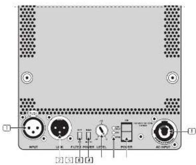
INPUT audio input jack accepts balanced XLR connections from audio sources. Pin 1 ground pin 2 hot pin 3 cold:
LINK audio output jack sends out a copy of the INPUT signal for use with other speakers. The LINK jack accepts balanced XLR connections: Pin 1 = ground; pin 2 = hot (+); pin 3 = cold (-). Multiple enclosures may be driven from a single audio source. Simply plug the signal source output into the first speaker's INPUT XLR socket, and then patch that speaker's XLR LINK output to the next speaker's INPUT XLR socket.
FILTER switch can be used to insert a high-pass filter into the signal chain. When set to HPF, the high-pass filter is engaged. When set to FR (Full Range), the high-pass filter is inactive.
POWER switch selects between AUTO or MAX (Manual); power modes. In AUTO mode, the amplifier switches into Standby if no signal is detected for a period of 20 minutes; if a signal is detected while in standby mode, the amplifier will power back on within 2 seconds.
[5] LEVEL control sets the output volume using a recessed potentiometer.
6 LED INDICATORS display the power status, signal status, and the status of the built-in speaker protection limiter (see "LED Functions" below).
POWER rocker switch turns the unit on/off.
(1) MAINS jack connects to AC power using cables equipped with Keutrik powerCON connectors (mating connector supplied).
Operation

AC Power Requirements
VXP Series loudspeakers are equipped with Keutrik powerCON mains connectors, which quickly lock into place inside the MAINS AC jack. This AC mains connector is supplied with each VXP Series loudspeaker.
The LAB GRUPPEN IDEA™ module in VXP loudspeakers features a universal power supply that will operate on any AC mains supply from 70 V to 265 V (+/- 10%) at 50 or 60 Hz, although with reduced power output capability at the low voltage extremes. This tolerance of varied AC mains voltage allows continued operation even when using long, thin power cables, or when the unit is powered by portable generators that cannot maintain full nominal voltage.
Auto and Manual Power Modes
VXP Series loudspeakers offer two modes for power on/off.
AUTO mode - This POWER switch setting is the default mode. AUTO engages the Auto Power Down (APO) feature which puts the IDEA™ module into Standby mode if no input signal is detected for a period of 20 minutes. Auto Power On (APO) turns the module back on in less than 2 seconds after a signal is detected at the input.
MANUAL mode - The power mode may be switched to MAN to disable the auto-power down and auto-power on functions. This allows use of an external power sequencer or manual control.
LED Functions
The LIM/PROT LED lights up when the built-in limiter is active and system is approaching clipping. An occasional flicker of the red LED on the loudest peaks is acceptable. If this LED remains red for more than the duration of brief dynamic peaks, or lights continuously, then the system is being overdriven. If the red LED illuminates excessively:
- Reduce the input level
- Reduce the output level of the mixer, or other source to the speaker
The SIG LED lights up when an audio signal is present at the INPUT jack.
The PWR LED lights up to indicate several system conditions:
- Green = Active (AC power present at MAINS connection, PWR switch ON)
- Red = Standley
- Amber = Temperature protection active
Cooling
Do not install this equipment in an enclosed space. Do not limit free ventilation and movement of air around the back panel. Ensure that there is at least 100 mm (4") of space around all sides of the product for ventilation. VXP Series loudspeakers do not have cooling fans; the highly efficient switch mode power supply and proprietary Class D output stage have low current draw and therefore require only the convection cooling provided by the rear panel heat sink.
Gain Structure
The VIP Series gain structure is designed to allow a low-level source device to drive the loudspeaker to full output. Maximum specified SPL will be achieved with a 4 dB input signal. There is sufficient headroom in the signal path to accommodate input levels of 10 or even 20 dBu, with high quality compression engaged as needed to maintain sonic integrity without clipping. To avoid any compression, or when a lower SPL output is desired, the input attenuator on the rear panel can be used to reduce gains/sensitivity.
Limiters
The limiters are carefully set-up to preserve the loudspeaker's dynamic headroom by allowing short term transients to pass through. Audible degradation will only become apparent when the LIN/PROT indicator is on constantly.
The limiting functions will protect the amplifier from long term overheating by attenuating voltage to the drive units. If used irresponsibly (constant hard clipping), sound quality will be compromised, in extreme cases drive units may also be damaged.
Equalisation
The VXP loudspeaker requires no equalisation or correction to overcome system limitations; equalization is necessary only to compensate for difficult acoustic environments. Over-equalisation can reduce system headroom and introduce phase distortion, resulting in degraded sound, if equalization is required, it should be applied gently and smoothly. Because VXP loudspeakers are point source and phase coherent designs, excessive equalization usually proves detrimental to the overall sound quality.
When one loudspeaker is used in close proximity to another, comb filtering effects can create coverage problems. (Comb filtering creates an uneven frequency response across the coverage area due to constructive and destructive interference effects between the two sources.) Comb filtering cannot be cured by equalisation and should be addressed with proper arraying as discussed in the following section.
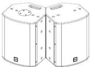
Arraying
Small alterations to loudspeaker positions can have the effect of minimising problematic combing frequencies. Arrays should be constructed so that the individual coverage patterns of each loudspeaker combine with minimal overlap. The design of the VXP Series loudspeakers greatly simplifies the creation of effective arrays, allowing seamless wide horizontal coverage using two loudspeakers without the need for tedious experimentation.
By placing the VXP Series loudspeakers with the 30 degree angled rear panels together, minimal dispersion pattern overlap is achieved, guaranteeing an extraordinarily smooth transition. In many applications the 90 or 75 degree dispersion pattern may be sufficient in the horizontal plane. It is also possible to stack the cabinets vertically using the above method (in a central cluster for example), where greater vertical dispersion is required.
natural_image
Technical line drawing of two cylindrical industrial enclosures with mounting holes and side grilles (no text or symbols)As shown in the above diagram, one of the VXP Series loudspeakers is inverted to achieve the optimum splay angle. The grille can be simply removed from this cabinet and be replaced for matching orientation. The grille is held in position by the two fixing screws on the top and bottom lips of the cabinet.
IMPORTANT NOTE: The mounting of a permanently installed sound system may be dangerous unless undertaken by qualified personnel with the required experience and certification to perform the necessary tasks. Walls, floors or ceilings must be capable of safety and securely supporting the actual load. The mounting accessory used must be safely and securely fixed both to the loudspeaker and to the wall, floor or ceiling.
When mounting rigging components on walls, floors or ceilings, ensure that all fixings and fasteners used are of an appropriate size and load rating. Wall and ceiling claddings, and the construction and composition of walls and ceilings, all need to be taken into account when determining whether a particular fixing arrangement can be safely employed for a particular load. Cavity plugs or other specialist fixings, if required, must be of an appropriate type, and must be fitted and used in accordance with the maker's instructions.
The operation of your speaker cabinet as part of a flown system, if installed incorrectly and improperly, can potentially expose persons to serious health risks and even death. In addition, please ensure that electrical, mechanical and acoustic considerations are discussed with qualified and certified (by local state or national authorities) personnel prior to any installation or flying.
Make sure that speaker cabinets are set up and flown by qualified and certified personnel only, using dedicated equipment and original parts and components delivered with the unit. If any parts or components are missing please contact your Dealer before attempting to set up the system.
Be sure to observe the local, state and other safety regulations applicable in your country. MUSIC Group, including the MUSIC Group companies listed on the enclosed "Service Information Sheet", assumes no liability for any damage or personal injury resulting from improper use, installation or operation of the product. Regular checks must be conducted by qualified personnel to ensure that the system remains in a secure and stable condition. Make sure that, where the speaker is flown, the area underneath the speaker is free of human traffic. Do not fly the speaker in areas that can be entered or used by members of the public.
Speakers create a magnetic field, even if not in operation. Therefore, please keep all materials that can be affected by such fields (discs, computers, monitors, etc.) at a safe distance. A safe distance is usually between 1 and 2 metres.
Controles
text_image
I INPUT 10kΩ FILTER POWER LEVEL POS/WR AC OUTPUT S S Anatural_image
Technical line drawing of a dual-cylinder mechanical component with mounting holes and central slots (no text or symbols)natural_image
Technical line drawing of two cylindrical electronic components with mounting holes and a central vertical axis (no text or symbols)natural_image
Technical line drawing of two cylindrical mechanical components with mounting holes and side ribs (no text or symbols)text_image
① INPUT L10 PST20 R00000 L10 R00000 AC RPLC ② ③ ④natural_image
Technical line drawing of two cylindrical industrial enclosures with mounting holes and side grilles (no text or symbols)natural_image
Technical line drawing of a dual-cylinder mechanical device with mounting holes and internal ribs (no text or symbols)natural_image
Technical line drawing of two cylindrical mechanical components with mounting holes and side slots (no text or symbols)text_image
I OUTPUT LEA FILTER POWER LETPL PDS/WR AC/OUTPUT S S Anatural_image
Technical line drawing of a cylindrical mechanical component with mounting holes and internal ribs (no text or symbols)natural_image
Technical line drawing of a dual-cylinder mechanical housing with mounting holes and side panels (no text or symbols)EN Technical Specifications
VXP 6 (-WH) VXP 8 (-WH) VXP 12 (-WH) VXP 1SHP (-WH)
| System | ||||
| Frequency response (Full range mode) | 85 Hz - 25 kHz ±3 dB80 Hz - 45 kHz -10 dB | 90 Hz - 35 kHz ±3 dB67 Hz - 45 kHz -10 dB | 70 Hz - 25 kHz ±3 dB55 Hz - 38 kHz -10 dB | 60 Hz - 25 kHz ±3 dB47 Hz - 10 kHz -10 dB |
| Frequency response (30 pass mode) | 130 Hz - 35 MHz +3 dB150 Hz - 45 MHz -10 dB | 130 Hz - 35 MHz +3 dB102 Hz - 45 MHz -10 dB | 100 Hz - 25 kHz +3 dB80 Hz - 38 MHz -10 dB | 100 Hz - 25 kHz +3 dB85 Hz - 38 kHz -10 dB |
| Nominal dispersion | 30° central at -6 dB point | 90° central at -6 dB point | 90° central at -6 dB point | 75° cortical at -5 dB point |
| Directivity factor (Ω) | 5.6 | 6.8 | 9.6 | 9.7 |
| Directivity index (Ω) | 7 | 7.9 | 9.8 | 9.9 |
| Dynamic range | 106 dB | 106 dB | 106 dB | 106 dB |
| Maximum SP | 125 dB peak | 125 dB peak | 129 dB peak | 131 dB peak |
| Crossover type | Passive 1.6 MHz with dynamic HI protection | Passive 1.7 MHz with dynamic HI protection | Passive 1 kHz with HI protection | Passive 1.3 kHz |
| Transducers | 150 mm (1 x 6") constant directly Dual ConcentricTM | 205 mm (1 x 8") constant directly Dual ConcentricTM | 305 mm (1 x 12") constant directly Dual ConcentricTM | 350 mm (1 x 15") constant directly PowerDualTM |
| Amplifier | ||||
| Maximum output power* | 1600W | 1600W | 1600W | 1600W |
| Type | Class-0 | Class-0 | Class-0 | Class-0 |
| Protection | Output current limiter, clip limiter, brownout protection and recovery, thermal | Output current limiter, clip limiter, brownout protection and recovery, thermal | Output current limiter, clip limiter, brownout protection and recovery, thermal | Output current limiter, clip limiter, brownout protection and recovery, thermal |
| Connectors | ||||
| Input | 1 x XLR balanced | 1 x XLR balanced | 1 x XLR balanced | 1 x XLR balanced |
| Input Impedance | 10 kΩ unbalanced, 20 kΩ balanced | 10 kΩ unbalanced, 20 kΩ balanced | 10 kΩ unbalanced, 20 kΩ balanced | 10 kΩ unbalanced, 20 kΩ balanced |
| Maximum Input level for clip | +4.5 dBx (hard clip at +14.5 dBx input signal) | +4.5 dBx (hard clip at +14.5 dBx input signal) | +4.5 dBx (hard clip at +14.5 dBx input signal) | +4.5 dBx (hard clip at +14.5 dBx input signal) |
| Link | 1 x XLR | 1 x XLR | 1 x XLR | 1 x XLR |
| Maine Supply | Neutalk powerCON 20kV | Neutalk powerCON 20kV | Neutalk powerCON 20kV | Neutalk powerCON 20kV |
| Controls | ||||
| Level | Recessed potentiometer | Recessed potentiometer | Recessed potentiometer | Recessed potentiometer |
| Filter | Hips pass (HPT)/ full range (TR), switchable | Hips pass (HPT)/ full range (TR), switchable | Hips pass (HPT)/ full range (TR), switchable | Hips pass (HPT)/ full range (TR), switchable |
| Power mode | Manual (MVR)/ auto (MVR), switchable | Manual (MVR)/ auto (MVR), switchable | Manual (MVR)/ auto (MVR), switchable | Manual (MVR)/ auto (MVR), switchable |
| Power Supply | ||||
| Type | Switch-mode autorange power supply | Switch-mode autorange power supply | Switch-mode autorange power supply | Switch-mode autorange power supply |
| Maine voltage | 100, 240 V~, 50/Hz Fz | 100, 240 V~, 50/Hz Fz | 100, 240 V~, 50/Hz Fz | 100, 240 V~, 50/Hz Fz |
| Power consumption | 50 W @ 5 max power | 75 W @ 5 max power | 125 W @ 5 max power | 150 W @ 5 max power |
| Endurance | ||||
| Dimensions (MM) | 334 x 216 x 216 mm(11.1 x 8.9 x 8.5") | 389 x 281 x 276 mm(16.3 x 11.1 x 10.9") | 487 x 371 x 361 mm(19.2 x 14.6 x 14.2") | 591 x 451 x 421 mm(123.3 x 17.5 x 16.6") |
| Net weight | 7.3 kg (15.5 lb) | 10.1 kg (22.2 lb) | 16.5 kg (41.9 lb) | 27.3 kg (62.1 lb) |
| Construction | 12 mm (5" plywood, vented and internally braced) | 15 mm (5" plywood, vented and internally braced) | 15 mm (5" plywood (enclosure) and 18 mm (5" ) plywood (front), vented and internally braced) | 18 mm (5" plywood, vented and internally braced) |
| Finish | Semi-mall black-paint (white optional) | Semi-mall black-paint (white optional) | Semi-mall black-paint (white optional) | Semi-mall black-paint (white optional) |
| White | Powder-coated perforated steel | Powder-coated perforated steel | Powder-coated perforated steel | Powder-coated perforated steel |
| Flying hardware | 2 x 1/8 pie slice bracket insertsBranking plate for optional VTH pole mount | 2 x 1/8 Filing inserts2 x 1/8 pie slice bracket inserts (in mm silicon key)Blanking plate for optional VTH pole mount | 8 x 10/8 Flying Inserts (contrast or landscape mounting)8 x 10/8 pie slice bracket inserts1 x Intrinsic carrying handlesBlanking plate for optional VTH pole mount | 8 x 10/8 corner Flying inserts8 x 10/8 pie slice bracket inserts1 x Intrinsic carrying handlesBlanking plate for optional VTH pole mount |
| Accessories | ||||
| Yoke Horizontal VX5.2/VX5 | Yoke Horizontal VX8 | Yoke Horizontal VX12 | Yoke Horizontal VX15 | |
| Yoke Horizontal VX5.2 VX6 - VH | Yoke Horizontal VX8 - VH | Yoke Horizontal VX12 - VH | Yoke Vertical VX15 | |
| VTH Top Hat | Yoke Vertical VX8/VX8.2 | Yoke Vertical VX12/VX12.2 - VH | VTH Top Hat | |
| Yoke Vertical VX8/VX8.2 - VH | Yoke Vertical VX12 VX12.2 - VH | |||
| VTH Top Hat | VTH Top Hat | |||
*Independent of limiters and driver protection circuits
theutrik and powerCON speaks ON are registered trademarks of Neutrik AG.
Only qualified personnel are allowed to modify the AC-Main cord and to adhere to all applicable national standards.
EN
Other important information

Important information
- Register online. Please register your new Music Tribe equipment right after you purchase it by visiting musctribe.com. Registering your purchase using our simple online form helps us to process your repair claims more quietly and efficiently. Also, read the terms and conditions of our warranty, if applicable.
- Malfunction. Should your Music Tribe Author and Reseller not be located in your vicinity, you may contact the Music Tribe Authorized Fulfill for your country listed under "Support" at musicitibe.com. Should your country not be listed, please check if your problem can be dealt with by our "Online Support" which may also be found under "Support" at musicitibe.com. Alternatively, please submit an online warranty claim at musicitibe.com BEFORE returning the product.
- Power Connections. Before plugging the unit into a power socket, please make sure you me using the correct mains voltage for your particular model. Equity fuses must be replaced with fuses of the same type and rating without exception.

Responsible Party Name: Music Tribe Commercial NV Inc.
Address: 5270 Procyon Street
Las Vegas NV 89118, United States
Phone Number: +1 702 800 8290
VXP SERIES
This equipment has been tested and found to comply with the limits for a Class A digital device, pursuant to part 15 of the FCC Rules. These limits are designed to provide reasonable protection against harmful interference when the equipment is operated in a commercial environment. This equipment generates, uses, and can radiate radio frequency energy and, if not installed and used in accordance with the instruction manual, may cause harmful interference to radio communications. Operation of this equipment in a residential area is likely to cause harmful
interference in which case the user will be required to correct the interference at his own expense.
This equipment complies with Part 15 of the FCC Rules. Operation is subject to the following two conditions:
[1] This device may not cause harmful interference, and
[2] This device must accept any interference received, including interference that may cause undesired operation.
Warning: Operation of this equipment in a residential environment could cause radio interference.
CE
Herby, Music Tribe declares that this product is in compliance with Directive 2014/35/EU, Directive 2014/30/EU, Directive 2011/65/EU and Amendment 2015/863/EU, Directive 2012/19/EU, Regulation 519/2012 REACH SVHC and Directive 1907/2006EC.
Full text of EU DoC is available at https://community.musictribe.com/
EU Representative: Music Tribe Brands DK A/S
Address: In Spring Olsens Gade 17, DK - 8200 Narhus M, Denmark