CVS 401 - Speaker TANNOY - Free user manual and instructions
Find the device manual for free CVS 401 TANNOY in PDF.

User questions about CVS 401 TANNOY
0 question about this device. Answer the ones you know or ask your own.
Ask a new question about this device
Download the instructions for your Speaker in PDF format for free! Find your manual CVS 401 - TANNOY and take your electronic device back in hand. On this page are published all the documents necessary for the use of your device. CVS 401 by TANNOY.
USER MANUAL CVS 401 TANNOY
natural_image
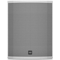
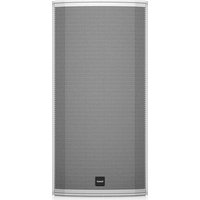
Row of five white audio speakers with mesh head covers, arranged in a row (no visible text or symbols)CVS Series
CVS 301 / CVS 301-BK
3" In-Ceiling Loudspeaker for Installation Applications
CVS 401 / CVS 401-BK
4" Coaxial In-Ceiling Loudspeaker for Installation Applications
CVS 601 / CVS 601-BK
6.5" Coaxial In-Ceiling Loudspeaker for Installation Applications
CVS 801 / CVS 801-BK
8" Coaxial In-Ceiling Loudspeaker for Installation Applications
CVS 801S
8" In-Ceiling Subwoofer Loudspeaker for Installation Applications
CVS 801S LZ
8" In-Ceiling Subwoofer Loudspeaker for
Installation Applications - Low Impedance Operation Only
2 CVS Series Quicks Scan Guide 3
EN
ES
EN Important Safety Instructions

Terminals marked with this symbol carry electrical current of sufficient magnitude to constitute risk of electric shock. the only high quality professional speaker tables with 15" TS or twist-locking plugs pre installed. All other installation or modification should be performed only by qualified personnel.
This symbol, wherever it appears, alerts you to the presence of uninsulated dangerous voltage inside the enclosure – voltage that may be sufficient to constitute a risk of shock.
This symbol, wherever it appears, alerts you to important operating and maintenance instructions in the accompanying literature. Please read the manual.
Caution To reduce the risk of electric shock, do not remove the top cover (or the rear section). No user serviceable parts include. Refer servicing to qualified personnel.
Caution To reduce the risk of fire or electric shock, do not expose this appliance to rain and moisture. The apparatus shall not be exposed to dripping or splashing liquids and no objects filled with liquids, such as wares, shall be plated on the apparatus.
Caution These service instructions are for use by qualified service personnel only. To reduce the risk of electric shock do not perform any servicing other than that contained in the operation instructions. Repairs have to be performed by qualified service personnel.
- Read these instructions.
- Keep these instructions.
- Hold all warnings.
- Follow all instructions.
- Do not use this apparatus near water.
- Clean only with dry cloth.
- Do not hold any ventilation openings, install in accordance with the manufacturer's instructions.
-
Do not install near any heat sources such as rotators, heat registers, stoves, or other apparatus (including amplifiers) that produce heat.
-
Do not defeat the safety purpose of the polarized or grounding-type plug. A polarized plug has two blades with one wider than the other. A grounding-type plug has two blades and a third grounding proong. The wide blade or the third proong are provided for your safety. If the provided plug does not fit into your outlet, consult an electrician for replacement of the obsovere outlet.
-
Protect the power cord from being walked on or pinched particularly at plugs, convenience receptacles, and the point where they eat from the apparatus.
-
Use only attachments/accessories specified by the manufacturer.

- Use only with the cart, stand, tripod, bracket, or table specified by the manufacturer, or sold with the apparatus. When a cart is used, use caution when moving the cart/apparatus combination to avoid
injury from tip-over.
-
Unplug this apparatus during lightning storms or when unused for long periods of time.
-
Refer all servicing to qualified service personnel. Servicing is required when the apparatus has been damaged in any way, such as power supply cord or plug in damaged, liquid has been spilled or objects have fallen into the apparatus, the apparatus has been exposed to rain or moisture, does not operate normally, or has been dropped.
-
The apparatus shall be connected to a AWNS socket outlet with a protective earthing connection.
-
Where the MAINS plug or an appliance coupler is used as the disconnect device, the disconnect device shall remain nearly operable.

- Correct disposal of this product: This symbol indicates that this product must not be disposed at with household waste, according to the WEE Directive (2012/19/EU) and
should be taken to a collection center formed for the recycling of waste electrical and electronic equipment (EEL). The misunderstanding of this type of waste could have a possible negative impact on the environment and human health due to potentially hazardous substances that are generally associated with EEL, at the same time, your corporation in the correct disposal of this product will contribute to the efficient use of natural resources. For more information about where you can take your waste equipment for recycling, please contact your local city office, or your household waste collection service. 18. Do not install in a confined space, such as a book case or similar unit.
-
Do not place naked flame sources, such as lighted candles, on the apparatus.
-
Please keep the environmental aspects of battery disposal in mind. Batteries must be disposed-of at a battery collection point.
-
This apparatus may be used in tropical and moderate climates up to 45°C.
LEGAL DISCLAIMER
Music Tribe accepts no liability for any loss which may be suffered by any person who relies on either wholly or in part upon any description, photograph, or statement contained herein. Technical specifications, appearances and other information are subject to change without notice. All trademarks are the property of their respective owners. Midas, Mark Teknik, Lab Sugopera, Luke, Tammy, Turbosound, TC Electronic, TC Hamilton, Behringer, Sugera, Oberheim, Murstone, Aston Microphones and Codestudio are trademarks or registrars trademarks of Music In The Global Brands Ltd. © Music Tribe Global Brands Ltd. 2021 All rights reserved.
LIMITED WARRANTY
For the applicable warranty terms and conditions and additional information regarding Music Tribe's Limited Warranty, please see complete details online at musictribe.com/warranty.
ES
BESCHRÄNKTE GARANTIE
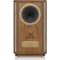
Thank you for purchasing this Tannoy Ceiling loudspeaker. This product range is suited for high-level music and speech reinforcement applications requiring exceptional sonic quality with uncompromised reliability.
The loudspeakers in this series are for indoor dry use.
Unpacking
Every Tannoy product and accessory is carefully inspected before packing. After unpacking, please inspect your product to make sure no damage has occurred in transit. In the unlikely event of any damage, would you please notify your dealer immediately and retain your shipping carton, as your dealer may ask you to return the faulty unit to them for inspection.
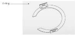
Each CVS loudspeaker is packed in pairs and provided with the following accessories as standard; C-Ring, tile-bridge kit, cut-out template, and paint mask. A plaster (mod) ring, 48" tile rail is also available as an optional extra.
Safety Notices
Some regional construction codes require the use of a secondary method of securing loudspeakers in ceiling to provide security of a backup support. A secondary support line should be attached from the safety loop on the rear of the product to a source point on the ceiling. Please consult the relevant construction codes in your region.
When using a power driver to install the product it is essential to use the correct torque level settings to avoid over tightening and damage to the ceiling material or clamps.
Recommended torque setting: 1.5 Km.
Tannoy will not be held responsible for any damages caused by the improper installation of these loudspeakers.
YIPO
The following table provides the results of the results of the results of the results of the results of the results of the results of the results of the results of the results of the results of the results of the results of the results of the results of the results of the results of the results of the results of the results of the results of the results of the results of the results of the results of the results of the results of the results of the results of the results of the results of the results of the results of the results of
Introducción
The following table provides the information in English: The information is provided by the United Kingdom for the years 1990, 2000, and 2005. The information is presented in a tabular format with the same time period (in years) for each year. The information is also provided in a tabular format with the same time period (in years) for each year.
12 CVS Series Quick Start Guide 13
Introduction
The following table provides the information obtained from the research of the 1995-1996 period: a research on the research of the research of the research of the research of the research of the research of the research of the research of the research of the research of the research of the research of the research of the research of the research of the research of the research of the research of the research of the research of the research of the research of the research of the research of the research of the research of the research of the research of the research of the research of the research of the research of the research of the research of
Introduction
Thank you for purchasing this Tannoy Ceiling loudspeaker. This product range is suited for high-level music and speech reinforcement applications requiring exceptional sonic quality with uncompromised reliability.
The loudspeakers in this series are for indoor dry use.
Unpacking
Every Tannoy product and accessory is carefully inspected before packing. After unpacking, please inspect your product to make sure no damage has occurred in transit. In the unlikely event of any damage, would you please notify your dealer immediately and retain your shipping carton, as your dealer may ask you to return the faulty unit to them for inspection.
Each CVS loudspeaker is packed in pairs and provided with the following accessories as standard: C-Ring, tile-bridge kit, cut-out template, and paint mask. A plaster (mud); ring, 48" tile rail is also available as an optional extra.
Safety Notices
Some regional construction codes require the use of a secondary method of securing loudspeakers in ceiling to provide security of a backup support. A secondary support line should be attached from the safety loop on the rear of the product to a source point on the ceiling. Please consult the relevant construction codes in your region.
When using a power driver to install the product it is essential to use the correct torque level settings to avoid over tightening and damage to the ceiling material or clamps.
Recommended torque setting: 1.5 Nm.
Tannoy will not be held responsible for any damages caused by the improper installation of these loudspeakers.
SNECTYMEET:
In order to be the following key points: (1) H_2 is a point of the first line, but the second line is a point of the second line. The second line is a point of the second line, and the third line is a point of the second line. Then, the second line is a point of the second line, and the third line is a point of the second line.
Introdução
For the first time, the number of observations is given for 2018 (35), and the number of observations is given for 2019 (40). The number of observations is given for 2020 (41), and the number of observations is given for 2021 (42).
Wprowadzenie
A. In fact, the case of the problem is a proof of the proof of the proof of the proof of the proof of the proof of the proof of the proof of the proof of the proof of the proof of the proof of the proof of the proof of the proof of the proof of the proof of the proof of the proof of the proof of the proof of the proof of the proof of the proof of the proof of the proof of the proof of the proof of the proof of the proof of the proof of the proof of the proof of the proof of the form
Product Feature Identification (CVS-601 shown)
Side View
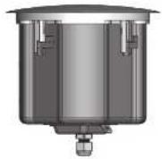
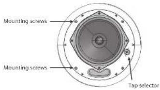
Front View
text_image
Mounting screws Mounting screws Tap selectorRear View
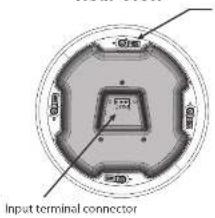
text_image
Input terminal connector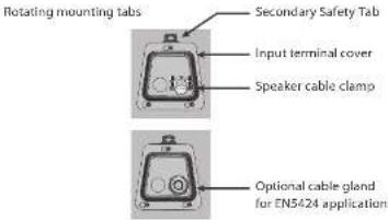
text_image
Rotating mounting tabs Secondary Safety Tab Input terminal cover Speaker cable clamp Optional cable gland for EN5424 applicationsAuxiliary support ring is not shown
Quick Star Guide
Accessories
Standard Accessories
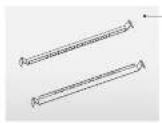
...Tile bridge kit Note: A tile bridge kit must always be sold when adding into suspended ceiling tiles.

text_image
TANOY CVS 601 Paint Mask Instructions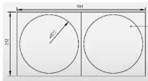
text_image
400 200 300Cut out template
Optional Accessories

text_image
Poster Mudl Ring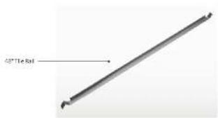
text_image
45°Tie Roll18 C45 Series
Installation Guide for Suspended Ceilings
NOTE: The speaker images shown are for guidance only, and may not exactly represent your particular model.
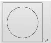
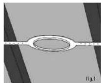
- Remove the ceiling tile from its frame and place it on a flat surface. Mark the cut-out area on the ceiling tile by tracing around the template provided. (Fig.1)
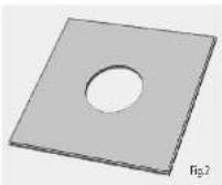
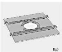
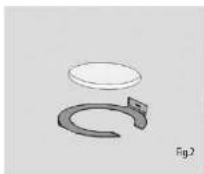
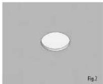
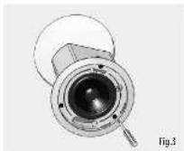
- Cut out the hole in the ceiling tile using a circular saw or pad saw (Fig.2). Place the C-ring and tile-bridge on top of the ceiling panel, aligning the C-ring over the hole, and screw the C-ring to the tile bridge using the fixings provided. (Fig.3)
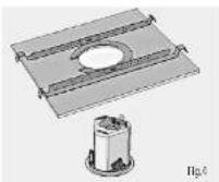
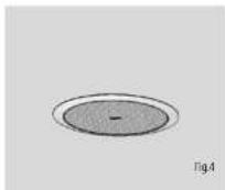
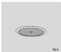
- Slide the speaker assembly through the hole and turn the screws on the front of the speaker to extend the mounting wings. Tighten the screws until a firm grip is achieved. If using a power driver, Tannoy recommends a torque setting of 1.5 Nm. (Fig.4) DO NOT OVERTIGHTENI
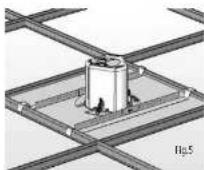
- Slide the tile panel back into the suspended ceiling. The tile bridge ends will catch over the railings, supporting the weight of the speaker. (Fig.5)
- Connect a secondary support line to the safety tax. Some construction codes require use of this secondary support point, which should connect to a separate secure support point using a suitable support line. Consult construction codes in your region. Go to page 15 for instructions on string and set-up instructions.
Installation Guide for Drywall Ceilings
NOTE: The speaker images shown are for guidance only, and may not exactly represent your particular model.
- Mark the cut-out area on the ceiling by trading around the template provided. (Fig.1)
- Cut out the hole in the ceiling using a pad saw, then slide the C-ring into the ceiling, aligning it over the cut-out hole. (Fig.2)
- Go to page 15 for wiring and set-up instructions then return to point 4 below.
- Connect a secondary support line to the safety tab. Some construction codes require use of this secondary support point, which should connect to a separate secure support point using a suitable support line. Consult construction codes in your region.
- Slide the speaker assembly through the hole and turn the screws to extend the mounting wings. Tighten the screws until a firm grip is achieved. If using a power driver, Tanney recommends a torque setting of 1.5 km. (Fig.3) DO NOT OVERTIGHTEN!
- Insert grille by pushing it onto the speaker.
Quick Star Guide
19
EN

Installation Instructions for Optional Plaster Ring
An optional plaster (mud) ring bracket is available from Tannoy. This bracket is designed to be pre-installed into newly constructed, non-suspended ceilings.
NOTE: The speaker images shown are for guidance only, and may not exactly represent your particular model.
-
Hall or screw the plaster ring to the joints. (Fig.1)
-
Lay the speaker wiring to where the speaker will be fitted and complete the plastering work on the ceiling.
-
Cut out the hole in the ceiling using a pad saw. (Fig.2)
-
Go to page 15 for instructions on wiring then return to point 5 below.
-
Connect a secondary support line to the safety tab. Some construction codes require use of this secondary support point, which should connect to a separate secure support point using a suitable support line. Consult construction codes in your region.
-
Side the speaker assembly through the hole and turn the screws to extend the mounting wings. Tighton the screws until a firm grip is achieved. If using a power driver, Tannoy recommends a torque setting of 1.5 Nm. (Fig.3) DO NOT OVERTIGHTEN!
-
Insert grille by pushing it onto the speaker. (Fig.4)
Quick Star Guide
Wiring and Setting Up
NOTE: The speaker images shown are for guidance only, and may not exactly represent your particular model.
We recommend the use of insulated speaker wiring of between 12 and 18 AWG.
WARNING: The power to the amplifier must be turned OFF when making connections to the loudspeakers. All connections must be checked before turning the amplifiers.
- Remove the wiring cover at the back of the speaker can to access the removable Euro-type connector plug and socket.
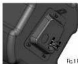
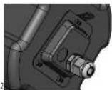
- The speakers come with a standard speaker cable clamp (Fig.1), and an optional gland for EN5424 applications (Fig.2). (Please note that EN5424 does not cover the CYS 801S and CYS801SLZ subwoofers.)
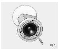
- Feed the cable through and attach to the Euro-type connector (Fig.3).
- For connection to an amplifier, use Pins 1 and 2 (Figs.3, 4, 5):
• Make sure that the wiring polarity is correct, where:
• Pin 1 is positive
• Pin 2 is negative
For connection to additional speakers in a distributed line (Fig.4)
Pins 3 and 4 are used to keep thru to additional speakers:
• Make sure that the wiring polarity is correct, where:
• Pin 3 is positive
• Pin 4 is negative

text_image
25V Power Amplifier Fig.4 Typical connections of two loudspeakers in a 70V distributed system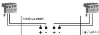
text_image
+ - + - + - + - + - + - + - + - + - Fig.5 Typical for 图 5 Typical forFig.5 Typical connections of two loudspeakers in a stereo system
- Tighten the cable clamp or cable gland and plug in the Euro-type connector to the loudspeaker. Replace the rear cover and securely tighten the supplied screws.
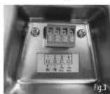
- The speaker is fitted with a multi-tap transformer for use in distributed-line systems (Fig. 6). There is also a LOZ tap. Select the required tap before pushing the grill in place. The average impedance of each speaker in this range is 8 Ohms in the LOZ setting.
CAUTION: THE SPEAKER IS SUPPLIED IN LOW IMPEDANCE MODE. NEVER CONNECT THE SPEAKER TO A 70/100 VOLT AMPLIFIER WHILE THE SPEAKER IS SET FOR LOW IMPEDANCE (LOZ).


Fig.6 Speaker Tap Selector Switches
text_image
Stress PowerAmplifier Fig.5 Connection| Performance | ||||||
| Frequency response(1 dB, -3 dB) | 85 Hz-10 kHz 102 Hz | -20 kHz 105 Hz-20 kHz 88 Hz | -20 kHz 65 Hz-200 kHz 66 Hz | -200 Hz | ||
| Frequency response(10 dB) | 68 Hz 20 kHz 70 Hz | 20 kHz 74 Hz 20 kHz 65 Hz | 20 kHz 31 Hz 200 kHz 53 Hz | 200 Hz | ||
| Sensitivity at 1Hz/1V | 35 dB | 84 dB | 90 dB | 90 dB | 92 dB | 92 dB |
| Directivity factor (Ω)averaged 1 kHz to6 kHz | 4.1 | 5.4 | 7.3 | 10.3 | N/A | N/A |
| Directivity index (Ω)averaged 1 kHz to6 kHz | 6.1 | 7.3 | 8.6 | 10.1 | N/A | N/A |
| Powerhandling (LoQ) | ||||||
| *1 Average | 20 Ω | 30 Ω | 50 Ω | 30 Ω | 320 Ω | 100 Ω |
| Programme | 40 Ω | 60 Ω | 100 Ω | 180 Ω | 230 Ω | 290 Ω |
| Peak | 50 Ω | 120 Ω | 200 Ω | 350 Ω | 450 Ω | 400 Ω |
| Recommendedamplifier power | 40 Ω @ 8.0 | 60 Ω @ 6.0 | 100 Ω @ 8.0 | 185 Ω @ 8.0 | 200 Ω @ 8.0 | 200 Ω @ 6.0 |
| Nominal Impedance(Switch to LoQ) | 8.0 | 8.0 | 5.0 | 8.0 | 8.0 | 8.0 |
| Rated maximum SPI(1m, Switch to LoQ) | 101 dB | 102 dB | 110 dB | 111 dB | 115 dB | 115 dB |
| Average | 98 dB | 99 dB | 107 dB | 110 dB | 112 dB | 112 dB |
| Peak SPI | 104 dB | 105 dB | 113 dB | 116 dB | 118 dB | 118 dB |
| Transformertaps | 15 W/7.5 W | 25 W/12.5 W | 30 W/15 W | 50 W/30 W | 80 W/40 W | N/A |
| 70 V | 3.8 W/1.0 W | 6.3 W/5.2 W | 7.5 W/3.8 W | 15 W/7.5 W | 25 W/10 W | N/A |
| 100 V | 15 W/7.5 W/1.5 W | 25 W/12.5 W/6.5 W | 30 W/15 W/25 W | 50 W/30 W/15 W | 80 W/40 W/25 W | N/A |
| Coverage angles | ||||||
| 500 Hz | 180° | 180° | 180° | 180° | N/A | N/A |
| 1 Hz | Horizontal: 133°Vertical: 130° | Horizontal: 125°Vertical: 118° | Horizontal: 124°Vertical: 124° | Horizontal: 126°Vertical: 118° | N/A | N/A |
| 2 Hz | Horizontal: 79°Vertical: 67° | Horizontal: 82°Vertical: 81° | Horizontal: 80°Vertical: 80° | Horizontal: 124°Vertical: 102° | N/A | N/A |
| 4 Hz | Horizontal: 163°Vertical: 160° | Horizontal: 85°Vertical: 86° | Horizontal: 76°Vertical: 92° | Horizontal: 69°Vertical: 63° | N/A | N/A |
| Transducers | ||||||
| Low frequency | 76 mm (5) PP cone | 100 mm (4) PP cone | 165 mm (6.5) PP cone | 200 mm (8) PP cone | 200 mm (2) Paper cone | 202 mm (8) Paper cone |
| High frequency | N/A | 20 mm (0.79%)cassally mounted | 20 mm (0.75%)cassally mounted | 25 mm (1%)cassally mounted | N/A | N/A |
| Physical | ||||||
| Enclosure | Blind mount (BM) | Blind mount (BMV) | Blind mount (BMV) | Blind mount (BMV) | Blind mount (BMV) | Blind mount (BMV) |
| Black can | Anodized steel | Anodized steel | Anodized steel | Anodized steel | Anodized steel | Anodized steel |
| Brake | Reflex loadedUL 94V Coated ABS | Reflex loadedUL 94V Coated ABS | Reflex loadedUL 94V Coated ABS | Reflex loadedUL 94V Coated ABS | Reflex loadedUL 94V Coated ABS | Reflex loadedUL 94V Coated ABS |
| Cable | Aluminum,powder coated | Aluminum,powder coated | Aluminum,powder coated | Aluminum,powder coated | Aluminum,powder coated | Aluminum,powder coated |
| Safety features | Rear enclosure safety ring for load-bearing band | Rear enclosure safety ring for load-bearing band | Rear enclosure safety ring for load-bearing band | Rear enclosure safety ring for load-bearing band | Rear enclosure safety ring for load-bearing band | Rear enclosure safety ring for load-bearing band |
| Clamping design | Security toggle clamp | Security toggle clamp | Security toggle clamp | Security toggle clamp | Security toggle clamp | Security toggle clamp |
| Connectors | Euroblock-style connector with screw terminals(with input cover and cable gland supplied) | Euroblock-style connector with screw terminals(with input cover and cable gland supplied) | Euroblock-style connector with screw terminals(with input cover and cable gland supplied) | Euroblock-style connector with screw terminals(with input cover and cable gland supplied) | Euroblock-style connector with screw terminals(with input cover and cable gland supplied) | Euroblock-style connector with screw terminals(with input cover and cable gland supplied) |
| CYS 301 | CYS 401 | CYS 601 | CYS 801 | CYS 901S | CYS 901S 12 | |
| Dimensions | ||||||
| Bevel diameter (lit. max diameter) | 200 mm (8") | 200 mm (8") | 254 mm (10") | 306 mm (12") | 305 mm (12") | 305 mm (12") |
| Rear face of bottle to rear of back cart | 130 mm (5.32") | 150 mm (5.91") | 208 mm (8.19") | 270 mm (8.35") | 282.50 mm (11.52") | 293.50 mm (11.52") |
| Rear face of bottle to top of safety loop | 148 mm (5.63") | 163 mm (6.42") | 231 mm (8.72") | 225 mm (8.86") | 305.5 mm (12.03") | 306.5 mm (12.03") |
| Rear face of bottle to rear of first cabin | 155 mm (6.10") | 175 mm (6.89") | 233 mm (9.13") | 237 mm (9.33") | 312.5 mm (12.5") | 313.5 mm (12.5") |
| Hole capacity diameter | φ172 mm (6.77") | φ172 mm (6.77") | φ222 mm (8.74") | φ273 mm (10.75") | φ273 mm (10.75") | φ273 mm (10.75") |
| Net weight | 2.71 kg (5.10 lbs) ±1.07% | 2.77 kg (6.09 lbs) ±1.02% | 2.8 kg (6.36 lbs) ±1.09% | 5.35 kg (11.77 lbs) ±1.07% | 2.95 kg (17.45 lbs) ±1.08% | 7 kg (15.4 lbs) ±1.09% |
| Included accessories | Metal grille, cable gland, free conduit, C-ring, the bridge kit, paint mask, outlet template | Metal grille, cable gland, free conduit, C-ring, the bridge kit, paint mask, outlet template | Metal grille, cable gland, free conduit, C-ring, the bridge kit, paint mask, outlet template | Metal grille, cable gland, free conduit, C-ring, the bridge kit, paint mask, outlet template | Metal grille, cable gland, free conduit, C-ring, the bridge kit, paint mask, outlet template | Metal grille, cable gland, free conduit, C-cring, the bridge kit, paint mask, outlet template |
| Optional accessories | Mud ring 68" The rail | Aud ring 48" The rail | Mud ring 68" The rail | Mud ring 48" The rail | Mud ring 48" The rail | Mud ring 48" The rail |
| Padded quantity | 1 pair | 1 pair | 1 pair | 1 pair | 1 pair | 1 pair |
*1 Average power rating is under IEC-shaped pink noise with a 6dB crest factor for 100 hours continuously.
Other important information

Important information
-
Register online. Please register your new Music Tribe equipment right after you purchase it by visiting musctribe.com. Registering your purchase using our simple online form helps us to process your repair claims more quietly and efficiently. Also, read the terms and conditions of our warranty, if applicable.
-
Malfunction. Should your Music Tribe Authorized Reseller not be listed in your vicinity, you may contact the Music Tribe Authorized Further for your country listed under "Support" at musicite.com. Should your country not be listed, please check if your problem can be dealt with by our "Online Support" which may also be found under "Support" at musicite.com. Alternatively, please submit an online warranty claim at musicite.com BEFORE returning the product.

Informations importantes
Hereby, Music Tribe declares that this product is in compliance with Directive
2011/05/EII and Amendment 2015/B03/EII, Directive 2012/19/EU, Regulation 149/2012 PEACHSVIC and Direction 1607/2006/EU, and this paper is created in our
3.9/2012 RECHSATE AND OPECTIVE 1507, 2006, TC, and this pass applicable to IAE Directive 2014/30/11. LT Directive 2014/35/11.
Full text of EU DoC is available at https://community.musictribe.com/
EU Representative: Music Tribe Brands DKA/S
Address: U Slang Ulsens Gade 17, DK - 8200 Paribus N, Denmark
EN