Back Can IW - Speaker TANNOY - Free user manual and instructions
Find the device manual for free Back Can IW TANNOY in PDF.


User questions about Back Can IW TANNOY
0 question about this device. Answer the ones you know or ask your own.
Ask a new question about this device
Download the instructions for your Speaker in PDF format for free! Find your manual Back Can IW - TANNOY and take your electronic device back in hand. On this page are published all the documents necessary for the use of your device. Back Can IW by TANNOY.
USER MANUAL Back Can IW TANNOY
natural_image
Technical line drawing of a mechanical component with two views: top shows a square frame with internal components, bottom shows a rectangular bracket with vertical supports (no text or symbols)PCI and QCI Series In-Wall Back Can and Pre-Mount Kits
Back Can IW
Back Can for PCI 5DC IW, PCI 6DC IW, and QCI 6DC IW In-Wall Loudspeakers
PMK 5 IW
Pre-Mount Kit for PCI 5DC IW In-Wall Loudspeakers
PMK 6 IW
Pre-Mount Kit for PCI 6DC IW and QCI 6DC IW In-Wall Loudspeakers
2 PMK I/W and Back Car IV/Quick Stat Guide 3
EN
ES
Important Safety Instructions
Terminals marked with this symbol carry electrical current of sufficient magnitude to constitute risk of electric shock. the only high quality professional speaker tables with 15" TS or twist, locking plugs pre installed. All other installation or modification should be performed only by qualified personnel.
This symbol, wherever it appears, alerts you to the presence of uninsulated dangerous voltage inside the enclosure - voltage that may be sufficient to constitute a risk of shock.
This symbol, wherever it appears, alerts you to important operating and maintenance instructions in the accompanying literature. Please read the manual.
Caution To reduce the risk of electric shock, do not remove the top cover (or the rear section). No user serviceable parts include. Refer servicing to qualified personnel.
Caution To reduce the risk of fire or electric shock, do not expose this appliance to rain and moisture. The apparatus shall not be exposed to dripping or splashing liquids and no objects filled with liquids, such as wares, shall be plated on the apparatus.
Caution These service instructions are for use by qualified service personnel only. To reduce the risk of electric shock do not perform any servicing other than that contained in the operation instructions. Repairs have to be performed by qualified service personnel.
- Read these instructions.
- Keep these instructions
- Head all warnings.
- Followall instructions.
- Do not use this apparatus near water.
- Clean only with dry cloth.
- Do not block any ventilation openings install in
accordance with the manufacturer's instructions -
Do not install near any heat sources such as radiators, heat registers, stores, or other apparatus (including amplifiers) that produce heat.
-
Do not defeat the safety purpose of the polarized or grounding-type plug. A polarized plug has two blades with one wider than the other. A grounding-type plug has two blades and a third grounding proong. The wide blade or the third proong are provided for your safety. If the provided plug does not fit into your outlet, consult an electrician for replacement of the obsovere outlet.
-
Protect the power cord from being walked on or pinched particularly at plugs, convenience receptacles, and the point where they eat from the apparatus.
-
Use only attachments/accessories specified by the manufacturer.
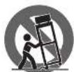
- Use only with the cart, stand, tripod, bracket, or table specified by the manufacturer, or sold with the apparatus. When a cart is used, use caution when moving the cart/apparatus combination to avoid
injury from tip-over
-
Unplug this apparatus during lightning storms or when unused for long periods of time.
-
Refer all servicing to qualified service personnel. Servicing is required when the apparatus has been damaged in any way, such as power supply cord or plug in damaged, liquid has been spilled or objects have fallen into the apparatus, the apparatus has been exposed to rain or moisture, does not operate normally, or has been dropped.
-
The apparatus shall be connected to a MANG socket outlet with a protective earthing connection.
-
Where the MAINS plug or an appliance coupler is used as the disconnect device, the disconnect device shall remain nearly operable.

- Correct disposal of this product: This symbol indicates that this product must not be disposed of with household waste, according to the WEE Directive (2012/19/EU) and
should be taken to a collection center formed for the recycling of waste electrical and electronic equipment (EEL). The misunderstanding of this type of waste could have a possible negative impact on the environment and human health due to potentially hazardous substances that are generally associated with EEL, at the same time, your corporation in the correct disposal of this product will contribute to the efficient use of natural resources. For more information about where you can take your waste equipment for recycling, please contact your local city office, or your household waste collection service. 18. Do not install in a confined space, such as a book case or similar unit.
-
Do not place naked flame sources, such as lighted candles, on the apparatus.
-
Please keep the environmental aspects of battery disposal in mind. Batteries must be disposed-of at a battery collection point.
-
This apparatus may be used in tropical and moderate climates up to 45°C.
LEGAL DISCLAIMER
Music Tribe accepts no liability for any loss which may be suffered by any person who relies either wholly or in part upon any description, photograph, or statement contained herein. Technical specifications, appearances and other information are subject to change without notice. All trademarks are the property of their respective owners. Vidas, Klark Teknik, Lab Suggers, Lake, Tanney, Turbosound, TC Electronic, TC Helicon, Behringes, Sugera, Osterheim, Auratone, Aston Microphones and Coledudio are trademarks or registered trademarks of Music in The Global Brands Ltd. © Music Tribe Global Brands Ltd. 2021 All rights reserved.
LIMITED WARRANTY
For the applicable warranty terms and conditions and additional information regarding Music Tribe's Limited Warranty, please see complete details online at musictribe.com/warranty.
ES
BESCHRÄNKTE GARANTIE
Thank you for purchasing this Accessory for Tanmoy Dual Concentric In Wall Loudspeakers for Installation Applications.
The Back Can IV is an optional accessory for the PCI 5DC IV, PCI 6DC IV, and QCI 6DC IV in-wall loudspeakers.
The PMK 61W is an optional pre-mount kit for the PCI 6DC1W, and QCI 6DC1W in-wall loudspeakers.
The PMK 51W is an optional pre-mount kit for the PC 5DC1W in wall loudspeaker.
The PMK kits can be used with or without the Back Can I/W.
The Back Can IW can be used with or without the PMK kits.
Each accessory is available separately, and this quick start guide covers all.
Unpacking
Every Tannoy product is carefully inspected before shipment. After unpacking, please inspect your product to ensure no damage has occurred in transit. In the unlikely event of damage, please notify your dealer and retain all shipping materials as your dealer may require return shipment.
Safety Notices
Tanney will not be held responsible for any damages caused by the improper installation of these loudspeaker accessories.
ES
Introducción
Product Feature Identification
PMK Pre-Mount Kit
PMK 5 IW is used for the PCI 5DC IW
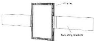
PMK 6 IW (shown below) is used for the PCI 6DC IW and QCI 6DC IW loudspeakers
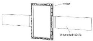
text_image
Frame Mounting ProductsBack Can IW
for PCI 5DC IW, PCI 6DC IW, and QCI 6DC IW loudspeakers
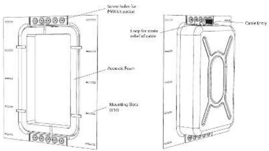
text_image
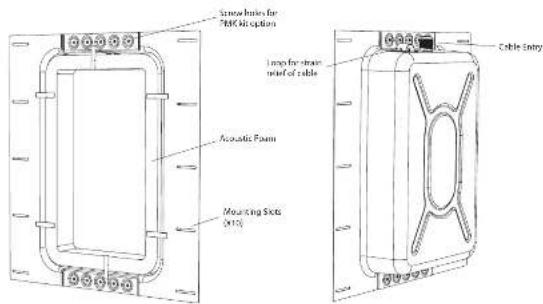
Secure holes for PAKkit outlet Loop for strain reheat of outlet Acoustic Foam Mounting Slots (0140) Cable EntryInstallation Guide
Back Can Installation
WARNING: This procedure requires the use of personal protection equipment, such as safety glasses and gloves.
WARNING: To avoid potential damage to your loudspeaker, ensure that the power amplifier is switched OFF prior to connecting or disconnecting any cables.
WARNING: Make sure that there are no power lines, other cables, or plumbing such as water, sewer, gas lines in the chosen location.
The Back Can IW is an optional Back Can that can be used for the PCI 5DC IV, PCI 6DC IV, and the OCI 6DC IV in-wall loudspeakers.
The procedure below describes the installation of the Back Can into a typical 2" x 4" stud wall with 16" centers, with drywall/pasterboard not yet installed.
After the Back Can and dry wall is installed, the PCI 5DC IV, PCI 6DC IV, and the QCI 6DC IV in-wall loudspeakers can be wired and installed, and the paint mask added during wall painting and finishing.
Procedure
Follow the procedure steps below in the order in which they are presented. Read all the instructions before starting.
- Locate a suitable mounting position for the loudspeaker that will offer optimum acoustic performance for the listening environment and audio system, and that is also practical and aesthetically pleasing.
- Carefully move the Back Can to the chosen location between the wall studs, and lift it to the desired height, allowing enough room for the speaker wire to enter the cable gland (Fig. 1).
- Make sure that the Bark Can is plump and level, then attach the Bark Can to the wall studs using 5 screws or nails per stud.
natural_image
Pure technical diagram of a rectangular component with internal channels and dimension lines, no text or symbols present.Fig. 1. Install the Back Can between the studwork
Wiring the Back Can
WARNING: To avoid potential damage to your loudspeaker, ensure that the amplifier is switched OFF prior to connecting or disconnecting any cables.
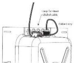
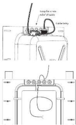
The speaker wire connections are made to the cable entry gland into the Back Can. A loop is provided to secure the cable before it enters the cable gland.
1. Loop the speaker wire once around the provided cable loop, and pass the cable through the cable gland and into the Back Can (Fig. 2) and past the acoustic foam inside the Back Can. Leave enough slack to make the connectors when that time comes. Tighten the cable gland, and be down the speaker cable to prevent it moving and rattling in operation. Make sure that the speaker cable does not come into contact with nails or screws that might damage the electrical insulation.
text_image
Loop for screen ided of cable Color Entry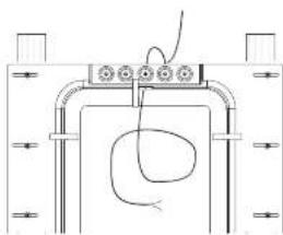
natural_image
Pure electrical circuit lines without any symbolsFig. 2. Install the wiring into the Back Can
Optional Pre-Mount Kit Installation
Two optional Pre-Mount Kits are available.
- The PMK S I/W is used with the PCI SDC I/W wall-mount loudspeaker
- The PMX 61W is used with the PCI 6DC 1W and QCI 6DC wall-mount loudspeakers
These provide a rectangular surround for a strong mounting surface for the clamping mechanism of the loudspeaker, and they make it easier to install the drywall.
The PMK Rits can be used with or without the Back Can.
The procedure below describes the installation of the PMR 6 IN pre-mount kit into a Back Can that has been installed into the wall studs and wired following the procedure shown on the previous page. The installation of the PMR 5 IN pre-mount kit is otherwise identical.
Preparing the PMK Pre-Mount Kit
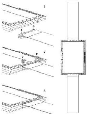
- Each pre-mount kit consists of two mounting brackets, a rectangular frame, and four small clips that help secure the brackets to the frame.
- Attach the mounting brackets to the top and bottom (shortest sides) of the rectangular frame (Fig. 3). Press the four clips in place, to hold the brackets in position
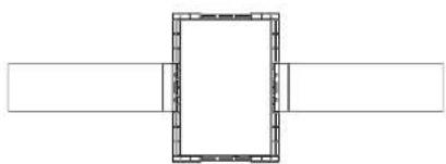
- The PMK kit can also be used without the Back Can, in which case, the mounting brackets are connected to the longer sides of the frame (Fig. 4).
text_image
Technical diagram showing three-step assembly of a structural component with labeled parts and directional arrowsFig. 3. Installing the PMK brackets to the frame
natural_image
Simple line drawing of a rectangular frame with horizontal and vertical lines (no text or symbols)Fig. 4. PMK assembly, for use without the PW Back Can
Installing the PMK into the Back Can
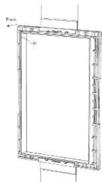
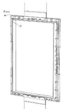
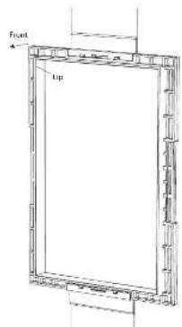
- Hold the PMK assembly onto the Back Can, with the rectangular lip of the frame pointing outwards, into the room (Fig. 5).
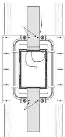
- Make sure the PMK assembly is centered, plumb, and level. Secure it to the Back Can using the four screws, and using the existing holes at the top and bottom of the Back Can (Fig. 6).
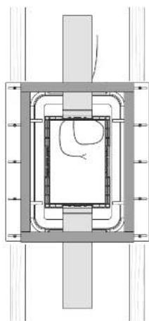
- Apply adhesive EVA tape around the front of the Back Can/PMK assembly as shown (Fig. 6b). We recommend EVA tape width 65mm , thickness 3mm , or similar. Note: Make sure that there are no gaps between the vertical and horizontal lengths of tape, so it is a continuous rectangle. (Any gaps may affect the performance of the loudspeaker.) Note: the EVA tape is required, even if the PMK kit is not used.
text_image
Pump LpFig. 5. Front of the PMK is the side with the lip
natural_image
Technical diagram of a mechanical assembly with no visible text or symbolsFig. 6. Install the PMK into the Back Can
natural_image
Pure technical diagram of a mechanical assembly with no visible text, numbers, or symbolsFig. 6b. Install the EVA tape to front of Back Can. Create a continuous rectangle, with no gaps.
Installing the PMK without the Back Can
If you are not using the Back Can, then there are two ways you can use the PMX kits. PMX Option 1
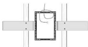
- Cut and add two pieces of 2x4 wood, horizontally as shown in Fig. 7, and nail and glue them securely in place to the vertical wall studs.
- Hold the PMK assembly in place, with the rectangular lip of the frame pointing outwards, into the room.
- Make sure the PMK assembly is centered, plumb, and level. Secure it to the horizontal pieces using four screws (Fig. 7).
- Run speaker wire to this location. Leave enough slack to make the connections when that time comes. Tie down the speaker cable to prevent it moving and rattling in operation. Make sure that the speaker cable does not come into contact with nails or screws that might damage the electrical insulation.
PMK Option 2
- Assemble the PMK with the mounting brackets attached to the longer sides of the PMK frame and then attach the PMK to the vertical wall studs. (See Fig. 4 on page 7).
- Hold the PMK assembly onto the wall studs, with the rectangular lip of the frame pointing outwards, into the room.
- Make sure the PAK assembly is centered, plumb, and level. Secure it to the wall studs using four woodstrews.
- Run speaker wire to this location (Fig. 8). Leave enough slack to make the connections when that time comes. Tie down the speaker cable to prevent it moving and rattling in operation. Make sure that the speaker cable does not come into contact with nails or screws that might damage the electrical insulation.
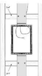
Fig. 7. PMK Attached to horizontal pieces
natural_image
Pure mechanical assembly diagram showing a rectangular frame with internal components and alignment lines (no text or symbols)Fig. 8. PMK attached to Wall Studs
Installing the Drywall
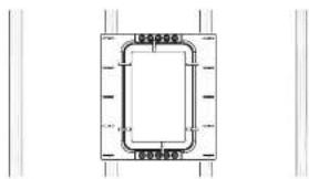
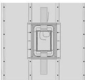
- The installation of drywall around the PMK location is best done using a single large sheet with the vertical center line centered over the PMK vertical centerline (Fig. 9).
- If you want to cut the drywall aperture before installation, use the PMK aperture as a guide. Step 5 below describes cutting after the installation. Use whichever method you prefer.
- Use adhesive on the wall studs and the front face of the Back Can fill used; and install the drywall using drywall screws approximately 8 to 10 inches apart. This will help prevent wall rattling and drywall movement and noises during operation. If the loudspeaker is being installed on an interior wall, then adhesive and extra screws may also be added to the drywall used in the room behind the loudspeaker.
- Note: Before adding any drywall screws where the metal Back Can is installed, drill small pilot holes into the metal of the Back Can.
- After the drywall installation, carefully cut out the hole in the drywall with a suitable handtool, using the inside aperture of the PMK as a guide (Fig. 10 and 11). Be careful not to cut the speaker wires or cut into the Back Can acoustic foam. Make sure the drywall aperture is no larger than the inside aperture of the PMK frame. Remove any dust or debris from within the Back Can.
- The PCI 5DC IV, PCI 6DC IV, and QCI 6DC IV quick start guide includes the procedures for installing the loudspeakers into the wall apertures.
natural_image
Top-down schematic of a mechanical or architectural component with no visible text, numbers, or symbols.Fig. 9. Drywall Screws, PMK with Back Can

natural_image
Pure architectural or mechanical diagram with vertical supports and a central square component (no text or symbols)Fig. 10. Drywall Screws, PMK without Back Can
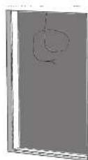
Fig. 11. Drywall Cutout (with PMK)
Cutout Procedure without the PMK
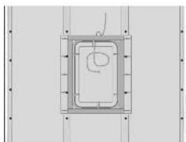
If you are using the Back Can, but not the PMK pre-mount kits, then follow this procedure below for cutting out the drywall.
Rectangular cutout templates are supplied with the loudspeakers, and act as a guide for cutting out the correctly sized hole in the wall [Fig. 12].
Follow the procedure steps below in the order in which they are presented. Read all the instructions before starting.
- In the position of the Back Can, and the supplied template to the wall, centered exactly on the center of the Back Can IV, and in the Portrait Orientation.
- Using the template, carefully cut out a hole in the drywall using a suitable handtool. Be careful not to damage the Back Can IV, its acoustic foam, or the speaker wires. Remove any dust and debris from the hole (Fig. 13 and 14).
- The PCI 5DC IV, PCI 6DC IV, and QCI 6DC IV quick start guide includes the procedures for installing the loudspeakers into the wall apertures.
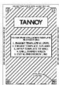
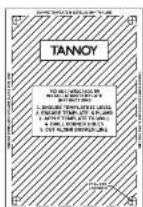
Fig. 12 Drywall Cutout Dimensions
natural_image
Pure technical diagram of a square frame with internal circular cutout and alignment lines (no text or symbols)Fig. 13. Back Can I'W without PMK
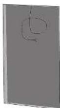
Fig. 14. Drywall Cutout
text_image
Frame Mounting BracketVolver Puedo IW
para altavoces PCI 5DC IW, PCI 6DC IW y QCI 6DC IW
text_image
Screw flutes for PAC Kit option Loop for strain and of cable Automatic Foam Mounting Side (210) Cable EntryGuía de instalación
natural_image
Pure electrical circuit lines without any symbolstext_image
Loop for rail rail of cable Cable Entrytext_image
Technical diagram showing three-step assembly steps of a structural component with labeled parts 1, 2, and 3.natural_image
Simple line drawing of a rectangular frame with two horizontal bars on both sides (no text or symbols)text_image
Front Topnatural_image
Technical diagram of a mechanical assembly with no visible text or symbolsnatural_image
Pure technical diagram of a mechanical or architectural component with no visible text, numbers, or symbols.natural_image
Pure mechanical assembly diagram showing a rectangular frame with internal components and alignment lines (no text or symbols)natural_image
Pure technical diagram of a mechanical assembly with no text, numbers, or symbolsnatural_image
Pure diagram of a rectangular frame with vertical supports and dots, no text or symbols presentnatural_image
Pure technical diagram of a square frame with internal lines and arrows, no text or symbols presentFig. 13. Back Can IV sin PMX
text_image
Frame Mounting ProductsRetour Can IW
text_image
Secure holes for PARKlet outlet Loop for strain reheat of outlet Acoustic Foam Mounting Slots (310) Case Entrynatural_image
Pure electrical circuit lines without any symbolstext_image
Loop for steam releef of cable Cable Entry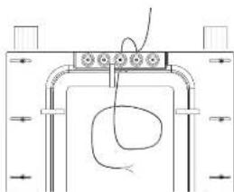
natural_image
Pure mechanical diagram showing a bracket with internal components and a curved wire, no text or symbols present.text_image
Technical diagram showing three-step assembly of a structural component with labeled parts and directional arrowsnatural_image
Simple line drawing of a rectangular frame with horizontal and vertical lines (no text or symbols)text_image
Front Topnatural_image
Technical diagram of a mechanical assembly with no visible text or symbolsnatural_image
Pure technical diagram of a mechanical assembly with no visible text, numbers, or symbolsnatural_image
Pure mechanical assembly diagram showing a rectangular frame with internal components and alignment lines (no text or symbols)natural_image
Pure technical diagram of a mechanical assembly with no text, numbers, or symbolsnatural_image
Pure architectural or mechanical diagram showing a central square with horizontal bars and vertical supports (no text or symbols)natural_image
Pure technical diagram of a square component with internal channels and mounting holes, no text or symbols presentFig. 13. Retour Can PW sans PAIX
PMK 6 IW (shown below) is used for the PCI 6DC IW and QCI 6DC IW loudspeakers
text_image
Frame Mounting BracketZurück kann IW
text_image
Screw flutes for PAC Kit option Loop for strain and of cable Automatic Foam Mounting Side (210) Cable EntryBack Can Installation
natural_image
Pure electrical circuit lines without any symbolstext_image
Loop for wire wire of cable Cable Entrynatural_image
Simple line drawing of a rectangular frame with two horizontal bars on both sides (no text or symbols)text_image
Front Topnatural_image
Technical diagram of a mechanical assembly with no visible text or symbolsnatural_image
Pure technical diagram of a mechanical or architectural component with no visible text, numbers, or symbols.natural_image
Technical diagram of a mechanical assembly with labeled components (no readable text or symbols)natural_image
Pure mechanical assembly diagram showing a rectangular frame with internal components and alignment lines (no text or symbols)natural_image
Pure technical diagram of a mechanical assembly with no text, numbers, or symbolsnatural_image
Pure architectural or mechanical diagram with vertical lines and a central rectangular cutout (no text or symbols)natural_image
Pure technical diagram of a square frame with internal components and alignment lines (no text or symbols)text_image
Frame Mounting ProductsVoltar Can IW
text_image
Secure holes for PARK list option Loop for strain reheat of oxide Acoustic Foam Mounting Slots (310) Case EntryGuia de instalação
natural_image
Pure electrical circuit lines without any symbolsFig. 1. Instale a lata trascira entre as vigas

text_image
Loop for strain relief of cable Cable Entry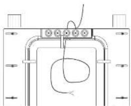
natural_image
Pure mechanical diagram showing a bracket with internal components and a curved wire, no text or symbols present.text_image
Technical diagram showing three-step assembly steps of a structural component with labeled parts and a close-up view.natural_image
Simple line drawing of a rectangular frame with horizontal and vertical lines (no text or symbols)text_image
Front Topnatural_image
Technical diagram of a mechanical assembly with no visible text or symbolsnatural_image
Pure technical diagram of a mechanical assembly with no visible text, numbers, or symbolsnatural_image
Pure diagram of a rectangular frame with internal lines and a curved line, no text or symbols presentFig. 8. PMK anexado a pregos de parede
Instalando o Drywall
natural_image
Pure technical diagram of a mechanical assembly with no text, numbers, or symbolsnatural_image
Pure architectural or mechanical diagram with vertical and horizontal lines and a central rectangular cutout (no text or symbols)Fig. 10. Parafusos de drywall, PWK sem lata posterior
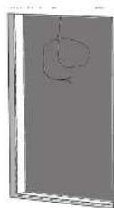
Fig. 11. Recorte de drywall (com PMK)
natural_image
Pure technical diagram of a rectangular frame with internal lines and mounting holes, no text or symbols presentFig. 13. Back Can I'W sem PMK
Fig. 14. Corte de drywall
text_image
Frame Mounting BracketIndietro Can IW
text_image
Screw holes for *PSC Kit option Loop for strain nord of cable Automatic Foam Mounting Side (10) Cable Entrynatural_image
Pure technical diagram of a rectangular component with internal channels and dimension lines (no text or symbols)text_image
Loop for drain relier of cable Cable Entrynatural_image
Simple line drawing of a rectangular frame with two horizontal bars on both sides (no text or symbols)text_image
Front Topnatural_image
Technical diagram of a mechanical assembly with no visible text or symbolsnatural_image
Pure technical diagram of a mechanical or architectural component with no visible text, numbers, or symbols.natural_image
Pure technical diagram of a rectangular component with internal structure, no text or symbols presentnatural_image
Pure technical diagram of a mechanical assembly with no text, numbers, or symbolsnatural_image
Pure diagram of a rectangular frame with vertical supports and a central hand symbol, no text or labels present.natural_image
Pure technical diagram of a square frame with internal components and alignment lines (no text or symbols)Fig. 13. Indietro Can MW senza PMK
text_image
Frame Mounting ProductsTerug Can IW
text_image
Secure holes for PAKkit outlet Loop for strain reheat of outlet Acoustic Foam Mounting Slots 0310 Cable EntryInstallatie gids
natural_image
Pure electrical circuit lines without any symbolstext_image
Loop for steam bolted cable Cable E-ray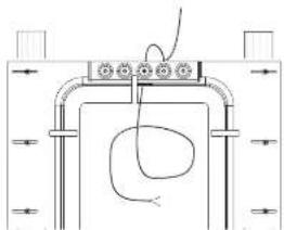
natural_image
Pure electrical circuit lines without any symbolsAft. 2. Installeer de bedrading in de Back Can
text_image
Technical diagram showing three-step assembly steps of a structural component with labeled parts and directional arrowsnatural_image
Simple line drawing of a rectangular frame with horizontal and vertical lines (no text or symbols)natural_image
Technical diagram of a mechanical assembly with no visible text or symbolsAlb. G. Installeer de PMK in de Back Can
Quick Star Guide
61
text_image
Front Topnatural_image
Pure technical diagram of a mechanical or architectural component with no visible text, numbers, or symbols.natural_image
Pure diagram of a rectangular frame with internal lines and a curved line, no text or symbols presentnatural_image
Pure technical diagram of a mechanical assembly with no text, numbers, or symbolsnatural_image
Pure architectural or mechanical diagram with vertical and horizontal lines and a central rectangular cutout (no text or symbols)natural_image
Pure technical diagram of a square component with internal structure and mounting holes (no text or symbols)text_image
Frame Mounting BracketsTillbaka Kan IW
text_image
Screw holes for *PAC Kit option Loop for strain nose of cable Automatic Foam Mounting Side (210) Cable EntryInstallationsguide
Installation på baksidan
natural_image
Pure technical diagram of a rectangular frame with dimension lines, no text or symbols presentFig. 1. Installera den balore burken mellan pinnbuiten
text_image
Loop for screen wheel of cable Cable EntryFig. 2. Installera ledningarna i den bakre burken
text_image
Technical diagram showing three sequential steps of a structural assembly with labeled components and directional arrows.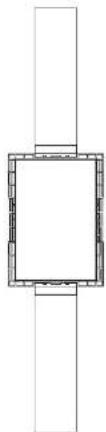
natural_image
Pure architectural line drawing of a square frame with vertical supports (no text or symbols)natural_image
Simple line drawing of a rectangular frame with two horizontal bars on both sides (no text or symbols)Fig. 4. PMK-monitoring, for alternating utan IW Back Can
Installera PMK i baksidan
natural_image
Technical diagram of a mechanical assembly with no visible text or symbolsFig. 6. Installera PMK i den bakre burken
text_image
Front Topnatural_image
Pure technical diagram of a mechanical or architectural component with no visible text, numbers, or symbols.natural_image
Technical diagram of a mechanical assembly with labeled components (no readable text or symbols)natural_image
Pure mechanical assembly diagram showing a rectangular frame with internal components and alignment lines (no text or symbols)natural_image
Pure technical diagram of a mechanical assembly with no visible text, numbers, or symbolsnatural_image
Pure diagram of a rectangular frame with vertical supports and a central hand symbol, no text or labels present.Fig. 10. Glpssknvar, PMK utan ryqgburk
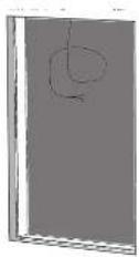
Fig 11. Utskärning av gips (med PMK)
natural_image
Pure technical diagram of a square frame with internal components and alignment lines (no text or symbols)text_image
Frame Mounting ProductsPowrót Can IW
text_image
Secure holes for PARKlet outlet Loop for strain reheat of outlet Acoustic Foam Mounting Slots (310) Cable Entrynatural_image
Pure electrical circuit lines without any symbolstext_image
Loop for strain reload of cable Cable End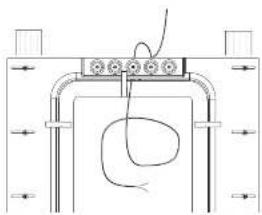
natural_image
Pure mechanical diagram showing a bracket with internal components and a curved wire, no text or symbols present.text_image
Technical diagram showing three-step assembly steps of a structural component with labeled parts and directional arrowsnatural_image
Simple line drawing of a rectangular frame with two horizontal bars (no text or symbols)text_image
Front -10natural_image
Technical diagram of a mechanical assembly with no visible text or symbolsnatural_image
Pure technical diagram of a mechanical assembly with no text, numbers, or symbolsnatural_image
Pure diagram of a rectangular frame with internal lines and a curved line, no text or symbols presentnatural_image
Pure technical diagram of a mechanical assembly with no text, numbers, or symbolsnatural_image
Pure architectural or mechanical diagram with vertical and horizontal lines and a central rectangular cutout (no text or symbols)natural_image
Pure technical diagram of a square frame with internal circular cutout and alignment lines (no text or symbols)Side Mounted Wings End Mounted Wings
text_image
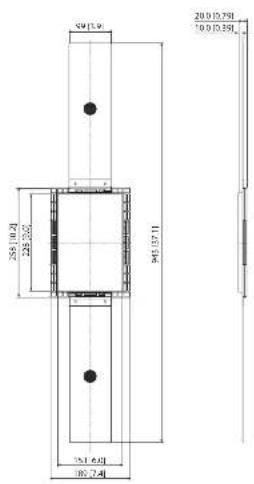
50.154 20.01278 10.01359 35.10.21 229.202 94.12711 151.641 186.241Dimerskors an den [och]
PMK 6 IW
text_image
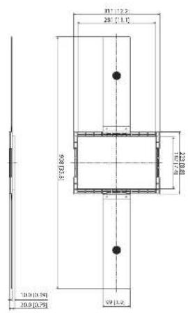
10.7±2.5 28.7±1.5 90.0±3.5 10.7±2.8 10.9±3.9 10.9±3.79 59±3.5Side Stressed Wings and Mounted Wings
text_image
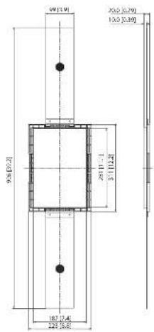
59 [1.9] 256 [5.79] 135 [3.30] 9% [0.2] R7211.15 1 - 4.82 187.14 225.68Диноколья кели [д.к.н]
Other important information

Important information

Informations importantes

Hereby, Music Tribe declares that this product is in compliance with Directive
2011/65/Ell and Amendment 2015/B63/Ell, Directive 2012/19/EU, Regulation
519/2012 RANCH SWK and Directive 1507/2006/TC, and this pass applicable to IAE Directive 2014/30/III. II Directive 2014/35/TII.
Full text of EU DeC is available at https://community.musictribe.com/
EU Representative: Music Tribe Brands DKA/S
Address: U Slang Ulsens Gade 17, DK - 8200 Paribus N, Denmark
EN