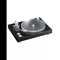
TN-5BB-M - Turntable TEAC - Free user manual and instructions
Find the device manual for free TN-5BB-M TEAC in PDF.


| Product Type | Turntable |
| Brand | TEAC |
| Model | TN-5BB-M |
| Drive | Belt drive, DC motor |
| Speeds | 33⅓, 45, 78 rpm |
| Cartridge | Ortofon 2M Red (MM type) |
| Tracking force | 1.8 g (adjustable) |
| Tonearm | S-shaped, static balancing, effective length 223 mm |
| Audio outputs | XLR (1 pair) and RCA (1 pair) |
| Dimensions (W × H × D) | 450 × 148 × 351 mm (cover closed) |
| Weight | 10.5 kg |
| Power supply | AC adapter (GPL01BS-120130-A) |
| Power consumption | Standby ≤0.3 W, operation ≤20 W |
| Operating temperature | 5 °C to 35 °C |
| Platter material | Acrylic (30 cm diameter) |
| Included accessories | 45 rpm adapter, counterweight, cartridge holder, Ortofon 2M Red cartridge, platter, belt, pulley cover, dust cover, hinges, adjustment washers, hex keys (2.5 mm and 1.5 mm), audio cable, ground wire, AC adapter, alignment protractor, user manual |
| Warranty (United States and Canada) | 1 year parts and labor |
| Cleaning | With a dry cloth; avoid chemicals |
| Safety | Do not expose to rain or moisture; unplug during storms |
Frequently Asked Questions - TN-5BB-M TEAC
User questions about TN-5BB-M TEAC
0 question about this device. Answer the ones you know or ask your own.
Ask a new question about this device
Download the instructions for your Turntable in PDF format for free! Find your manual TN-5BB-M - TEAC and take your electronic device back in hand. On this page are published all the documents necessary for the use of your device. TN-5BB-M by TEAC.
USER MANUAL TN-5BB-M TEAC
natural_image
Technical line drawing of a rotary dial and its internal components (no text or symbols)OWNER'S MANUAL
MODE D'EMPLOI
MANUAL DEL USUARIO
BEDIENUNGSANLEITUNG
IMPORTANT SAFETY INSTRUCTIONS

CAUTION
RISK OF ELECTRIC SHOCK DO NOT OPEN

CAUTION: TO REDUCE THE RISK OF ELECTRIC SHOCK, DO NOT REMOVE COVLY (OR BACK). NO USER SERVICEABLE PARTS INSIDE, TO LET SERVICING TO QUALITED SERVICE PERSONNEL.

The lightning flash with arrowhead in an equilateral triangle is intended to alert the user to the presence of uninsulated "dangerous voltage" within the product's enclosure that could be of sufficient magnitude to constitute a risk of electric shock to persons.

The excitation point in an equilateral triangle is intended to alert the user to the presence of important operating and maintenance (servicing) instructors in the literature accompanying the appliance.
WARNING: TO PREVENT FIRE OR SHOCK HAZARD, DO NOT EXPOSE THIS APPLIANCE TO RAIN OR MOISTURE.
CAUTION
- DO NOT REMOVE THE EXTERNAL CASES OR CABNETS TO EXPOSE THE ELECTRONICS, NO USE SERVICEABLE PARTS AND SIDES.
- YOU ARE EXPLINING PROS.LMS WITH THIS PRODUCT, CONTACT THE STORE WHERE YOU PURCHASED THE UNIT FOR A SERVICE OFFERBA. DO NOT USE THE PRODUCT UNIL IT HAS BEEN REPAIRID.
- USE OF CONTROLS OR ADJUSTMENTS OR PERFORMANCE OF PROCEDURES OF ILIT THAN THOSE SPECIFIED - ECON MAY RESULT IN HAZARDOUS RADIATION EXPOSURE
1) Read these instructions.
2) Keep these instructions.
3) Head all warnings.
4) Follow all instructions.
5) Do not use this apparatus near water.
c) Clean only with dry cloth.
7) Do not block any ventilation openings. Install in accordance with the manufacturer's instructions.
8) Do not inste near any heat sources such as radiators, heat registers, stoves, or other apparatus (including amplifiers) that produce heat.
(3) Do not defeat the safety purpose of the polarized or grounding-type plug. A polarized plug has two blades with one wider than the other. A grounding type plug has two blades and a third grounding wrong. The wire blade on the ship promg are provided for your safety. If the provided plug does not fit into your outlet, consult an electrician for replacement of the obsolete outlet.
10) Protect the power cord from being walked on or pinched particularly at plugs, convenience receptacles, and the point where they exit from the coparatus.
11) Only use attachments/accessories specified by the manufacture.
1.2) Use only with the cart, stand, tripod, bracket, or table specified by the manufacturer; or sold with the apparatus. When a cart is used, use caution when moving the cart/apparatus combination to avoid injury from tip over.

13) Unplug this appearance during lightning storms or when unused for long periods of time.
14) Refer all servicing to qualified service personnel. Servicing is required when the apparatus has been damaged in any way, such as power supply cord or plug's de-megated, liquid has been spliced or objects have fallen into the apparatus, the apparatus has been exposed to rain or moisture, does not operate normally, or has been dropped.
- The apparatus draws nominal non-operating power from the AC outlet with its POWER or STANDAY/ON switch not in the ON position.
●The mains plug is used as the disconnect device, the disconnect device shall remain readily operable.
●Caution should be taken when using earphones or headphones with the product because excessive sound pressure (volume) from earphones or head phones can cause hearing loss.
CAUTION
- Do not expose this apparatus to drips of spasms.
- Do not place any objects filled with liquids, such as vases, on the apparel.
- Do not install this apparatus in a confined space such as a book case or similar unit.
- The apparatus should be located close enough to the AC outlet so that you can easily reach the power cord plug at any time.
IN USA/CANADA, USE ONLY ON 120V SUPPLY.
Model for USA
Supplier's Declaration of Conformity
Model number: N-5BB
trade name: ILAC
responsible party:
Pioneer & Onkyo U.S.A. Corporation
Address: 22828 Lockness Avenue, Torrance, CA 90501 U.S.A. Telephone number: 1 20 785 2600
This device complies with Part. 15 of the FCC Rules. Operation is subject to the following two conditions: (1) this device may not cause harmful interference, and (2) this device must accept any interference received, including interference that may cause undesired operation.
Information
This equipment has been tested and found to comply with the limits for a class B digital device, pursuant to Part 1 of the HCC Rules, these limits are designed to provide reasonable protection against harmful interference in a residential installation. This equipment generates, uses, and can rotate radio frequency energy end, if not installed and used in accordance with the instructions, may cause harmful interference to radio communications. However, there is no guarantee that interference will not occur in a particular installation. If this equipment does cause harmful interference to radio or television reception, which can be determined by turning the equipment off and on; the user is encouraged to try to correct, the interference by one or more of the following measures:
- Recent or relocate the equipment and/or the receiving antenna.
- Increase the separation between the equipment and receiver.
- Connect the equipment into an outlet on a circuit different from that to which the receiver is connected.
- Consult the dealer or an experienced factor/TV technician for help.
CAUTION
Changes or modifications not expressly approved by the party responsible for compliance could void the user's authority to operate the equipment.
Model for Canada
Industry Canada's Compliance Statement
The Class B digital apparatus comoles with Canadian IC-5-DC3.

Model for Europe

This product complies with the European Directives request, and the other Commission Regulations.
For European Customers
Disposal of electrical and electronic equipment and batteries and/or accumulators
a); A. electric/electronic equipment and waste batteries/accumulators should be disposed of separately from the municipal waste stream via collection facilities designated by the government or local authorities.
3) By disposing of electrical/electronic equipment and waste batteries/accumulators correctly, you will help save valuable resources and prevent any potential negative effects on human health and the environment.
c) Improper disposal of waste electrical/electronic equipment and batteries/accumulators can have serious effects on the environment and human health because of the presence of hazardous substances in the equipment.
d) The Waste Electrical and Electronic Equipment (WFFP), symbols, which show wheeled bins that have been crossed out, indicate that electrical/electronic equipment and batteries/accumulators must be collected and disposed of separately from household waste.
if a battery or accumulator contains more than the specified values of lead (Pb), mercury (Hg), and/or cadmium (Cd) as defined in the Battery Directive (P006/66/FC, 2013/56/FU), then the chemical symbols for these elements will be indicated beneath the WEEE symbol.
e) Return and collection systems are available to end users. For more detailed information about the disposal of old electrical/electronic equipment, and waste batteries/accumulators, please contact your city office, waste disposal service or the shop where you purchased the equipment.
Table of contents
Thank you for choosing IT AC
Read this manual carefully to get the best performance from this unit.
After reading it, keep it in a safe place for future reference.
IMPORTANT SAFETY INSTRUCTIONS....2
Before use....3
Handling records....3
Preparing the record player....4
Connections....6
Names and functions of parts....6
Basic operation....7
Dust power....8
Notes about record styluses....8
Changing the cartridge....8
Cartridge alignment (overhang adjustment)....9
Adjusting the scream lifter....10
Troub eshecting....10
Specifications....1
Company names, product names and logos in this document are the trademarks or registered trademarks of their respective owners.
Before use
Included accessories
Check to be sure the box includes a the supplied accessories shown below. Please contact the store where you purchased this unit if any of these accessories are missing or have been damaged during transportation.
Precautions for use
- Do not place anything on the dust cover. Objects on the cover might cause noise due to vibrations or fall off, especially during playback.
- Avoid placing the unit in direct sunlight, close to a source of heat or in other similar conditions. Do not place the unit on top of an amplifier or other equipment that might generate heat that exceeds the operating temperature range of this unit. Doing so could cause discoloration, deformation or malfunction.
- At the unit would become warm during operation, always leave sufficient space around it for ventilation. When installing this unit, leave a 100 space to least 20 cm (3/7) otherwise it and other devices and walls to allow good heat, division. When placing it in a rack, for example, leave a 35 cm (13 3/4") open above it and 10 cm (4/7) open behind it. Failure to provide these gaps could cause heat to build up inside and result in fire.
- DO NOT MOVE THE UNIT DURING PLAYBACK. During playback, the record rotates. Do not lift or move the unit during payback. Doing so may damage the record, the stylus, the cartridge or the unit.
●Aways remove the record before relocating or moving rail unit. Moving the unit with a record on the turntable (platter) could damage the record, the stylus and the cartridge or could cause a malfunction.
- The voltage supplied to the unit should match the voltage as printed on the rear panel. If you are in any doubt regarding this matter, consultant securities.
Maintenance
If the surface of the unit gets dirty, wipe it with a soft cloth or use diluted milk liquid soap. Allow the surface of the unit to dry completely before using.
- Do not use chemical cleaning cloths, thinner or similar substances as they could damage the surface of the unit.
CAUTION
For safety, disconnect, the power cord from the social before cleaning.
Using the TEAC Global Site
You can download updates for this unit from the D-AC Global site: http://teac-global.com/
In the TFAC Downloads section, click the desired language to open the Downloads website page for that language.
Handling records
Holding records
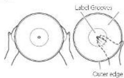
When holding a record or removing it from its sleeve, avoid touching the grooves by holding the record by its label and edge with one hand or by holding it by its edge with both hands.
Cleaning
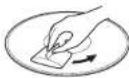
● Fingerprints and dust on a record can cause noise and the sound to slip, as we as damage the record itself and the sky us use a commercially-available record cleaner to clean records. Do not use thinner or anything other than a record clearer. Such chemicals could harm the surface of the record.
- When using a record cleaner, we the surface of the record in a circular motion, following the grooves.
Precautions
- Do not leave records in places that are exposed to direct sunlight or are very hot or very humid. Leaving a record in such a condition for a long time could result in warping, mole growth or other damage.
- Do not stack multiple records or place heavy objects on top of them. Do not leave records at an angle for long amounts of time either. Doing so could result in warping or other damage.
- Do not allow hard objects to directly touch the audio grooves. Doing so could cause scratches.
- After you finish playing a record, always put it back into its sleeve for storage. Leaving a record unprotected could result in warping or scratching;
- Do not use cracked records.
Preparing the record player
Keep the unit in standby while setting it up (D on page 6)
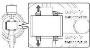
1 Cushions are attached to the tonearm for use during transportation. Remove them in the directions of the arrows.
2 Place the unit on a flat surface.
Place it on a fat surface so that the record can be accurately traced.
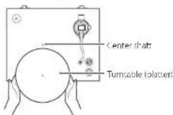
3 Install the turntable (platter).
Align the lumtable (platter) with the center shaft and install L.
■Place the large side of the hole down
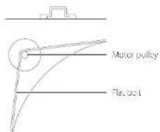
4 Loop the belt around the motor pulley.
Loop the included flat belt around the outside of the turntable (blatter), and then loop the belt around the motor pulley.
■Be careful not to let the rubber become twisted.
- Rotate the lumble (plate) several times to measure that the flat belt is secure.
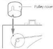
5 Install the pulley cover.
Align the small cutout in the pulley cover with the small protuberance on the pulley, as shown in the illustration below. If these are not aligned, the pulley cover will start
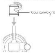
6 Install the counterweight.
Place the counterweight over the end of the tonearm, and press it gently as you turn it right to attach 1.
- When the counterweight can be moved toward the bearing, installation is complete.
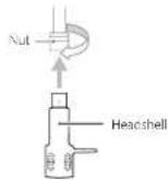
7 Install the headshell.
Insert the headshell on the end of the concern and turn the nut to secure it in place.
Confirming levelness and fine-tuning
In order to confirm the level placement of the turntable, we recommend using, for example, a commercially-available turntable leveling device. If the turntable is not level, follow the procedures below to adjust the heights of the feet to level the unit.
- If the want is too great, the following method might not be able to correct it.
1 Turn the foot on the low side counterclockwise to remove it.
2 Attach one of the included washers.
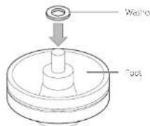
3 Reattach the foot in its original position.
4 Press down on the four corners of the unit to confirm that the weight is distributed evenly on the four feet.
If one of the feet is wobb y, attach a washer to it as explained above and adjust its height.
Balancing the tonearm and adjusting the tracking force
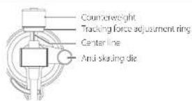
1 Press the STANDBY/ON button on the back of the unit to turn it on.
The tonearm after will not function if the power is STANDBY.
2 Set the anti-skating dial to zero.
3 Press the ARM LIFT button to raise the tonearm lifter. Then, shift the tonearm to the left slightly.
When the tonearm lifter is raised, the indicator in the ARM LIFT button will light.
4 Press the ARM LIFT button to lower the tonearm lifter.
5 Turn the counterweight and adjust so that the tonearm is level.
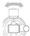
- Be careful not to let the cartridge stylus touch the unit.
- Remove the protective cover from the carriage before adjusting.
6 Return the tonearm to its original position, and place it on the tonearm holder.
7 Turn the tracking force adjustment ring so that the center line aligns with 0 on the scale.
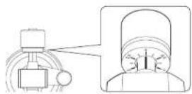
- Only turn the ring. Be careful, not to let the counterweight turn.
8 Turn the counterweight so that the tracking force adjustment ring scale matches the tracking force specified for the cartridge.
- The tracing force of the included cartridge is 1.8 g. So, turn it to 1.8 on the counterweight scale when using the included cartridge.
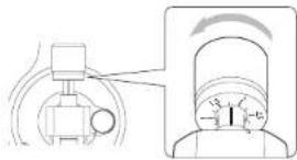
- turn in right from 0 in the direction of 0.5 and 1.0
9 Adjust the anti-skating dial.
Star, with it set to the same value as the tracking force and adjust it during record playback (page 7) to the position where the left and right volumes are balanced. In the illustration below, the tracking force is 1.8 g.
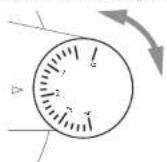
ATTENTION
Depending on the condition of a record, the left-right volume balance could become uneven and skipping could occur.
In such cases, try making the following adjustments.
If the sound jumps backward (stylus skips backward) slightly lower the art-skating dial setting.
If the sound jumps forward (stylus skips forward) slightly increase the anti-skating dial setting.
Adjusting the tonearm height
Follow the procedures below to adjust the tonearm height if it is not level during record playback after changing the cartridge or headshell.
1 Place a record on the turntable (platter), and put the record stylus on the edge of the record.
- Do not let the turntable (platter) cum.
2 Insert the included 2.5mm hex wrench into the height adjustment screw hole and turn it counterclockwise to unlock the tonearm base.
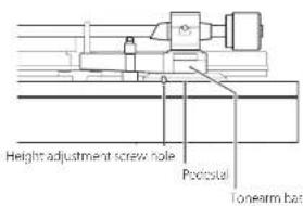
3 Hold the tonearm base, and adjust the height to make the tonearm level.
- He careful not to let the tonearm move right or left when adjusting the height.
4 Turn the hex wrench clockwise to lock the tonearm base.
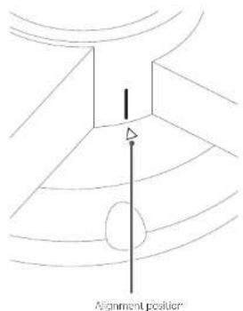
That tonearm base can move left and right relative to the pedestal. Align the guideline (white) on the tonearm base to the ▲ mark on the pedestal before locking it.
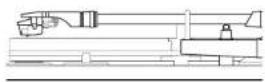
5 Play the record and confirm that the tonearm is now level.
Connections
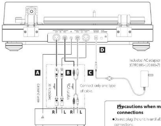
Amplifier or phono amplifier
Precautions when making connections
- Do not plug the unit in until after making all connections.
- Carefully read the manuals of the devices that you are connecting and follow their instructions when making connections.
A Grounding terminal (h)
Use the included ground wire to connect this grounding terminal to the grounding terminal of the amplifier, for example.
- This is NOT an electrical safety ground.
If noise from speakers is conspicuous
If a ground wire is connected to the grounding terminal of this unit, disconnecting it could reduce noise. Use the method (connected/disconnected) that has the least noise.
B Analog audio output connectors (L/R)
The cartridge signal is output directly through the analog audio output connectors (2/8).
Use these when connecting to an amplifier or other equipment that has PLONO input connectors. Connect to the appropriate PLONO input connectors according to the type of installed cartridge (MM or MC). The PLONO input connectors of some equipment might be setable for use with other MM or MC type input.
For details, refer to the operation manual of that equipment.
Use the following types of cables for connections.
X: R. X18 cables (sold separately) RCA: RCA cables
C DC input connector
After completing all other connections, connect the included AC adapter to this connector.
Confirm that the power plug of the AC adapter is plugged into a power outlet.
- Do not use any AC acceptor other than the one include.
Be sure to connect the power cord to an AC outlet that supplies the correct voltage. Connection to an outlet that supplies incorrect voltage could cause fire or electric shock.
Hold the power plug when plugging it into an outlet or unplugging it. Never pull or yank on the power cord.
Unplug the power cord from the outlet when you are not planning to use the unit for an extended period of time.
D STANDBY/ON button
Press the STANDBYON button to turn the unit on or put it in standby.
Names and functions of parts
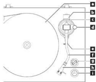
a Turntable (platter)
Place records centered on the turntable (platter).
b Counterweight
Tracking force adjustment ring
d Anti-skating dial
e Tonearm holder
This stand holds the tonearm in place.
f Tonearm
g Rotation speed setting knob
Select the rotation speed indicated on the record to be played.
Rotation will stop when this is set to 0.
h Headshell
This is a universal type that allows the cartridge to be changed easily.
i ARM LIFT button
Use to raise and lower the forearm
Press this button to raise the tonearm lifter, lighting the indicator in the button. Press this again to lower the tonearm lifter, causing the indicator to become unit.
We recommend using the tonearm lifter to avoid damaging records and styluses, because it is safer and more certain than using a finger to do so.
Basic operation
Playing records
1 Press the STANDBY/ON button on the back of the unit to turn it on.
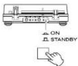
2 Open the dust cover slowly.
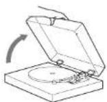
careful not to pinch your hand, for example, when opening and closing the dust cover.
3 Place a record on the turntable (platter).
When playing a 45 RPM large-hole single record, use the included adapter.
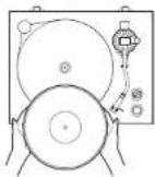
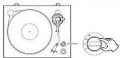
4 Select the rotation speed indicated on the record.
The rotation speed can be set to 33 1/3, 45 or 78 RPM.
5 Press the ARM LIFT button to raise the tonearm lifter.
When the tonearm litter is operating, the indicator will blink.
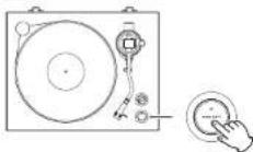
- You can also manually move the tonearm to above the record without raising the tonearm later and then slowly lower the tonearm to start playback.
6 Move the tonearm to the track where you want to start playback.
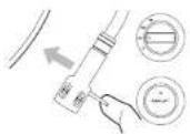
7 Press the ARM LIFT button to lower the tonearm lifter.
The tonearm lowers slowly until the stylus touches the record and playback begins.
- Close the cust cover curing record playback. Since doing this prevent is skipping caused by unintended contact and blocks external sound pressure, it makes noise less likely to occur.
not place anything on top of the dust cover.
ATTENTION
- During playback, do not touch the tonearm or the record. Doing so could damage the stylus tip and cause scratches on the record.
- Do not forcibly stop turntable (platter) rotation during playback. Since this product, is not a turntable designed for DJs (direct drive), doing something like this could cause malfunction.
During record playback feedback could occur if the volume is too out. If this happens, lower the volume of the amplifier.
When playback finishes
1 When the stylus reaches the lock groove of the record, the tonearm lifter will rise and the turntable (platter) will stop automatically.
The indicator in the ARM LIFT button will right.
2 Return the tonearm to its original position.
The turntable (platter) will start turning.
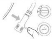
3 Turn the rotation speed setting knob to 0 to stop the turntable (platter).
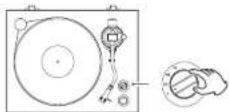
Automatic tonearm lifter
When shape new from the factory, the automatic longarm lifter, which raises the longarm when the stylus reaches the back groove of the record, is enabled.
Disabling the automatic tonearm lifter
Press the ARM LIFT button for five seconds until the indicator on the button blinks twice.
- Press the ARM LIFT button for five seconds again to enable the function.
●Disable the automatic tonearm litter if a 7-inch FP or other record is not played until its end.
Dust cover
Attaching the dust cover
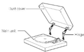
1 Insert the hinges completely into the hinge holders at the left and right ends of the back of the main unit.
2 Align the tops of the hinges with the dust cover hinge holders and insert them.
- Close the dust cover during playback. Since doing this prevents skipping caused by unintended contact and blocks external sound pressure, it makes noise less likely to occur.
- Do not open or close it when a record is playing. Doing so could, for example, cause the stylus to skip.
- Keep it closed whenever possible to keep dust out.
Removing the dust cover
Hold both edges of the dust cover and lift it slowly to remove it along with the hinges from the unit. Then, remove the hinges from the dust cover.
Opening and closing the dust cover
Opening
Hold the front edge of the dust cover and gently lift it open completely until it stops.
The dust cover will stay open in this position.
Closing
Gently lower the dust cover until it is closed.
He careful not to pinch your fingers, for example, when opening and closing the dust cover.
Notes about record styluses
- If the stylus becomes bent (damaged), it will no longer be able to accurately trace the groove. Since a bent stylus could also damage records and cause malfunction, handle styluses carefully.
●Always use a commercially available stylus cleaner to clean a stylus. Use of anything other than a stylus cleaner could damage the stylus.
Replacing the stylus
If the tip of the stylus becomes worn, not only will it worsen the sound quality, it could also damage records. After about 1000 hours of playback time, replace the stylus with one that we specify.
The cartridge installed in the product is an Ortofon 2M Red MM type cartridge.
When used normally, the 2M Red stylus should be replaced about every 1000 hours. Please purchase a commercially-available 2M Red replacement stylus.
- Follow the replacement instructions in the manual of the replacement, stylus.
ATTENTION
- Since loud noises could suddenly occur, put the unit into standby before changing the stylus.
●Be careful not to hurt your hand or the equipment. - Be careful not to allow small children to accidentally swallow styluses.
- Be aware that bent styluses, for example, that result from insufficient customer caution or an outside cause are not covered by the warranty.
Changing the cartridge
to change the cartridge, first remove the headshell from the tonearm.
●The cartridge installed in the product is an Ortofon 2M Red KM type cartridge.
- We recommend that you attach the protective cover to the cartridge before proceeding.
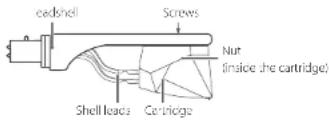
1 Disconnect the shell lead terminals from the cartridge.
2 Loosen the screws and remove the cartridge.
3 Attach the new cartridge and tighten the screws.
- Use screws that are suitable for the cartridge. See the illustration below for the position of the screws when attached.
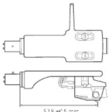
NOTE
To adjust the cartridge attachment position more accurately, follow the procedures in the following "Cartridge alignment (overhang adjustment)" section.
4 Connect the shell lead terminals to the cartridge.
●The signals and colors of the shell leads are shown below.
| Signal Color | |
| Left channel + White | |
| Left channel - Blue | |
| Right channel + Red | |
| Right channel - Green |
5 Balance the tonearm and adjust the tracking force.
Follow the procedures in "Balancing the tonearm and adjusting the tracking force" on page 4.
Cartridge alignment (overhang adjustment)
When installing a new cartridge or headshell on the TV-510, use the Cartridge Alignment Gauge to adjust the cartridge attachment position so that tracking error is minimized.
Cartridge Alignment Gauge overview
Use the template included with this product, or download the PDI from our website (https://sec打印/product/21-5bb/) and print: t at actual size.
After printing, carefully open a hole for the spindle, or use a utility knife to cut a cross into the spindle hole or the template.
ATTENTION
- In order to prevent the stylus from becoming caught and causing damage, print on photo paper, glossy paper or other paper with a smooth surface.
●After printing the PDF, confirm that the distance between the center of the spindle hole and B is exactly 50 mm. If this distance is incorrect, printing was not at actual size, so this cannot be used to attach the cartridge at the correct position.
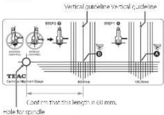
NOTE
●The vertical and horizontal lines are guidelines.
The distance from the forearm rotation central axis (toroarm pivot) to the center of the record is called the "pivot to spin a distance". The distance from the forearm pivot to the cartridge style tip is called the "effective length". The difference between the two is the overhang length. Only this overhang length is adjusted with basic cartridge adjustment. Using this adjustment too, however, the cartridge attachment position and angle can be adjusted more precisely, utilizing a setup that suppresses tracking error even more.
Cartridge attachment explanation
Temporarily fix the cartridge in position as explained in the previous "Changing the cartridge" section.
When adjusting the cartridge position, move the cartridge along the screw holes in alignment with the central axis of the cantilever and headshell. See the illustration below!
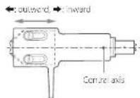
- The sides of the cartridge and the cantilever might not be parallel due to individual differences. This might be a slight inclination, but it cannot be ignored when making this adjustment, so aligns the central axis to that of the cantilever.
- To enable precise adjustment, of the cartridge position, partially tighten the screws used to attach the cartridge to the headshell to hold L in place temporarily. Tightening the screws too much will prevent adjustment of the cartridge position
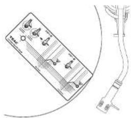
1 Place the Cartridge Alignment Gauge on the turntable so that the spindle goes through its spindle hole.
natural_image
Technical line drawing of a handheld electronic device with cable (no text or symbols)2 Move the Cartridge Alignment Gauge and the tonearm to find the position where the vertical line that passes through point A and the central axis of the headshell match.
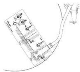
3 Make precise adjustments to the cartridge attachment position so that the stylus tip and point A are at the same position.
Refer to "Cartridge attachment explanation" for the relationship between the positions of the cartridge and the headshell.
4 Move the Cartridge Alignment Gauge and the tonearm to move the stylus tip to the point B position.
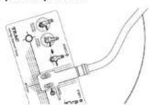
5 If the headshell is parallel to the guideline, proceed to the next step. If it is not parallel, refer to the illustration below and repeat adjustments from step 2.

6 Tighten the screws firmly, taking care not to shift the cartridge position.
7 Balance the tonearm and adjust the tracking force.
Follow the procedures in "Balancing the tonearm and adjusting the tracking force" on page 4
Adjusting the tonearm lifter
The height of the tonearm lifter on this unit is calibrated for the included cartridge.
if the cartridge is replaced with another, the style might not touch the record when the tonearm lifter is lowered or the stylus might not lift, far enough from the record when the tonearm lifter is raised. In such cases, adjust the height of the tonearm lifter.
Checking the tonearm lifter height
Check the following conditions at the inner and outer edges of the record.
Space occurs between the tonearm and the tonearm lifter when the tonearm lifter is lowered.
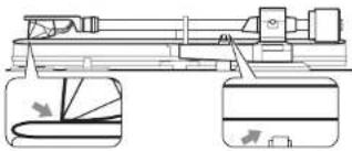
natural_image
Technical line drawing of a mechanical assembly with no visible text or symbols- If the tonearm contacts the tonearm litter, lower the height of the tonearm litter.
The stylus tip is separated from the record when the tonearm lifter is raised.
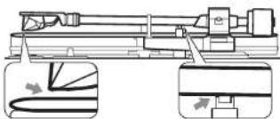
natural_image
Technical line drawing of a mechanical assembly with two views (top and side), no visible text or symbols- If the cartridge stylus contacts the record, raise the height of the tonogram filter.
Changing the height of the tonearm lifter
The height of the tonoarm after is fixed using the screw at the position shown in the illustration below.
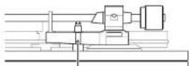
Height adjustment screw hole
1 Insert the included 1.5mm hex wrench into the height adjustment screw hole and turn it counterclockwise to loosen the screw.
2 After adjusting the height of the tone-arm lifter, insert the hex wrench into the height adjustment screw hole and turn it clockwise to secure the position of the tonearm lifter.
●The vertical movement range of the tonearm lifter cannot be adjusted.
3 After adjusting the height of the tonearm lifter, follow the previous instructions to check the height again.
Troubleshooting
you experience a problem with this unit, please check the following items before requesting service. Something other than this unit could also be the cause of the problem. Please also check that the connected devices are also being used properly. It still does not operate correctly, contact the retailer where you purchased the unit.
The unit does not turn on.
→Confirm that the AC adapter is plugged into an outlet. Then, press the STANDBYON button to turn the unit on (page 6).
Volume is low.
→ Confirm the connections (page 5). Connect to the appropriate PHONO Input connectors according to the type of installed cartridge (MM or MC), be PHONO input connectors of some equipment might be serrable for use with either MM or MC type input, for details, refer to the operation manual of the equipment.
Playback is not possible; there is noise.
→Remove the protective cover from the cartridge.
→Clean the stylus (page 8)
→If the stylus is worn out, replace it.
→ Place the unit as far away as possible from Vs, microwave ovens and other devices that emit electromagnet c waves.
Noise occurs when a record is playing.
Noise could occur if the tracking force is higher than cartridge's specified value. Readjust the tracking force so that it is the specified value (page 4).
The pitch is wrong.
→Set the rotation speed (JPM) to match the record (page 7).
The sound is skipping.
→ vibrations will cause skipping. Place this unit in a stable location.
→If the record is dirty, wipe it a can.
→Do not use scratched records.
→Balance the tonearm and readjust the tracking force (page 4).
If the tracking force is lower than the value designated by the cartridge, skipping is more likely to occur.
→ Confirm that the forearm is not contacting the forearm lifter (page 10).
Specifications
Turntable (platter)
Drive system
Rotation detection type: high-precision control belt drive Motor 100 motor Rotation speed 33/73 rpm, 45 rpm, 78 rpm Wave and flutter 0.1% or less Turnule (patter) Acrylic, 30cm (12") diameter
Cartridge
Type M/M Output voltage 5.5 mV, 1 kHz, 5 cm/s Tracking force 1.8 g Cartridge weight 7.2 g Included head shell weight 10 g (including screws, nuts and wires)
- the lifespan of a stylus depends on the use conditions but is usually about 1000 hours. - Replacement record stylus model: Orufer 2M Red
Tonearm
Tonearm type.... Static balanced S-shaped tonearm Effective tonearm length.... 223 mm Suitable cartridge weight.... 70-13 g ... 14-23 g (with the included headshell) Overhang.... 18 mm Tonearm height adjustment range.... about 6 mm
Analog audio outputs
Connectors....X-LR connectors (1 L/R pair) RCA connectors (1 L/R pair)
General
AC adapter power
Input AC 100-240V, 50-60Hz
Output..... DC 7.0V, 1.0A, 12.0W max
Power consumption
Standby 0.3 W or ess
On (33, 45, 78)....2.0 W or less
Weight 10.5 kg (23 1/4 lb)
Operating temperature range 5°C to 25°C
Dimensions (W × H × O) (including protrusions)
When the dust cover is closed
450×148×351mm:173/4"×57/8"×137/8"
When the dust cover is open
450×420×410 mm (173/4"×165/8"×161/4")
When the dust cover is removed
450×135×351mm(1/3/4"×5 3/8"×13/8")
(when tonearm at highest position)
●Performance data is specified at 20°C
Included accessories
15 32M adapter ×
Counterweight × 1
Headshell x
Ortofon 2M Red (MM type) pre installed
Turntable (platter) × 1
[at bel. × ]
Pulley cover × 1
Dust cover × 1
Hinces × 2
Foot height adjustment washers x 4
lonearm height adjustment hex wrench (2.5 mm) × 1
Tonearm fiber height adjustment hex wrench: 1.5 mm ^2 × 1
RCA audio cable x
Ground wire × 1
AC adaptor (GPEC185 120100 Z) x
Cartridge Alignment Gauge × 1
Owner's manual (this document, including warranty) x 1
- For information about the warranty, users living in the USA and Canada should see page 82 and the back cover (warranty document). Users living in Europe and other regions should see page 83.
- Specifications and appearance are subject to change without notice. - Weight and dimensions are approximate. Illustrations in this owner's manual might differ slightly from production models.
INSTRUCTIONS DE SÉCURITÉ IMPORTANTES

CAUTION
RISK OF ELECTRIC SHOCK DO NOT OPEN

ATTENTION : POUR RÉDUIRÉ LE RISQUE D'ÉLECTROCUITION, NL RTIRILZ PAS LE CAPOT (OU L'ARRIDU). AUCUNL PIÈOL INIUINE N'EST RÉPARABLE PAR CUIUSAILUR CONI LE TOUTLE RÉPARAT ON A UN SERVICE APRES-VENTE QUALIFIE.

6 Installez le contrepoids.
natural_image
Pure geometric diagram with curved lines and a vertical arrow, no text or symbols presenta Plateau
natural_image
Technical line drawing of a handheld device with attached cable (no text or symbols)natural_image
Technical line drawing of a mechanical assembly with no visible text or symbolsnatural_image
Technical line drawing of a mechanical assembly with two views (top and side), no visible text or symbolsPrises Prises XLR (I paire L/R)
Prises RCA (1 paire L/3)
Générales
Adaptateur secteur
Latree CA 100-240V, 50-501 z
CC12DV,10A,120Wmax.
Dimensions 1 × H × P (sailles incluses)
natural_image
Technical diagram showing a mechanical component and its rotation view (no text or symbols)natural_image
Pure geometric diagram with curved lines and a central arrow, no text or symbols presenta Plato giradiscos
natural_image
Pure electrical circuit lines without any symbolsnatural_image
Technical line drawing of a mechanical assembly with two views (top and side), no visible text or symbolsnatural_image
Technical line drawing of a mechanical assembly with two views (top and side), no visible text or symbolsnatural_image
Pure diagram of a 3D geometric shape with curved lines and an arrow, no text or symbols presentRCA (Cinch): Cinch-Kabel


Plattenteller
natural_image
Technical line drawing of a handheld device with attached cable (no text or symbols)natural_image
Technical line drawing of a mechanical device with two views (top and side), no visible text or symbolsnatural_image
Technical line drawing of a mechanical assembly with two views (top and side), no visible text or symbolsnatural_image
Technical diagram showing a mechanical component and its rotation dial (no text or symbols)natural_image
Pure geometric diagram with curved lines and a central arrow, no text or symbols present
Piatto del giradischi
natural_image
Technical line drawing of a handheld device with connectors and wiring (no text or symbols)natural_image
Technical line drawing of a mechanical assembly with two views (top and side), no visible text or symbolsnatural_image
Technical line drawing of a mechanical assembly with two views (top and side), no visible text or symbolsSpecifications....61
natural_image
Pure geometric diagram with curved lines and a central arrow, no text or symbols presentUitlijnpositie
Draaitafelplateau
natural_image
Pure electrical circuit lines without any symbolsnatural_image
Technical line drawing of a mechanical assembly with two views (top and side), no visible text or symbolsnatural_image
Technical line drawing of a mechanical assembly with two views (top and side), no visible text or symbolsGeluidsvolume is laag.
Justera armilyten....70
Felsökning....70
Specifikationer....71
a Skivtallrik
natural_image
Technical line drawing of a mechanical assembly with two views (top and side), no visible text or symbolsnatural_image
Technical line drawing of a mechanical assembly with two views (top and side), no visible text or symbolsRotationshastghet....33 1/3 rom, 45 rpm, 78 rpm
Svaj....0,1% o er mirde
Slóvtallrile...Akryl, 30 cm diameter
Patron
Typ MM
Utmaturingspanning.... 5.5 mV/1 kHz, 5 cm/s
Spåmingskraft 1,8 g
Patronakt....179
Drafts/cmperuromrède
Att (B × H × D, inklusive utskjutande delar)
Med dammskycdet stängt... 450 mm × 148 mm × 351 mm
Ned dammskyodet öppen: .. 450 mm × 420 mm × 410 mm
Med dammskycdet oort: ... 450 mm × 35 mm × 351 mm
Justeringsmall for patron (Cartridge Alignment Gauge) ×
Bruksanvisning (dette dokument) x
- Se sida 8.3 for information on garantin.
https://teac.jp/jp/ signature
お手入れ
natural_image
Diagram showing a mechanical device with a rotating knob and a close-up view of its internal components (no text or symbols)a ターンテーブル(プラッター)
×E
natural_image
Technical line drawing of a medical device with attached cable (no text or symbols)natural_image
Technical line drawing of a mechanical assembly with no visible text or symbolsnatural_image
Technical line drawing of a mechanical assembly with two views (top and side), no visible text or symbolsWarranty provisions (United States and Canada only)
Length of Warranty
The parts and labor warranty will be effective for one (1) year from the date of the original purchase for products not used for commercial purposes. For products used commercially, the warranty is ninety (90) days for magnetic heads and optic pickups, one (1) year for all other parts and ninety (90) days for labor.
Who Is Covered Under This Warranty
This warranty is valid only in the United States or Canada, dependents upon the country in which original purchase was made, and enforceable only by the origin purchaser within the country in which the purchase was made.
This warranty is not valid if the product was purchased through an unauthorized dealer.
What Is Not Covered Under This Warranty
●Damage to or deterioration of the external cabinet.
●Damage resulting from accident misuse, abuse, or neglect
- Damage resulting from failure to follow instructions contained in the products owners' manual or otherwise provided with the product.
●Damage occurring during shipment of the product (Claims must be present to the carrier).
●Damage resulting from the repair or attempted repair by anyone other than TEAC or an authorized TEAC service station.
- Damage resulting from modification or attempted modification of product not authorized by TEAC.
●Damage resulting from causes other than product defects, including lack of technical skills, competence, or experience of the user;
- Damage to any unit that has been altered or which the serial number has been defaced, modified or removed.
What TEAC Will Pay For
ILAC will pay all labor and material expenses for items covered by the warranty. Payment of shipping charges is covered in the next section.
How To Obtain Warranty Service
Your unit must be serviced by an authorized TEAC service station within the country in which the product was purchased. If you are unable to locate an authorized service station in your area, please contact TEAC at the applicable address shown at the end of this warranty statement. PLEASE DO NOT RETURN YOUR UNIT TO TEAC WITHOUT OUR PRIOR AUTHORIZATION. You must pay shipping charges if it is necessary to ship a product for service. However, if the necessary repairs are covered by warranty, we will pay the return shipping charges to any destination within the country in which the product was purchased. Whenever warranty service is required, you must present the original dated series receipt or other proof indicating the purchase place and date, as proof of warranty coverage.
LIMITATION OF IMPLIED WARRANTIES
ALL IMPLIED WARRANTIES, INCLUDING WARRANTIES OF MERCHANTABILITY AND FITNESS FOR A PARTICULAR PURPOSE, ARL LIMITED DURATION TO THE LING TO THIS WARRANTY.
EXCLUSION OF DAMAGES
TEACS LIABILITY FOR ANY DEFECTIVE PRODUCT IS LIMITED TO RELPAIR OF PLACLMINI OF ITIL PRODUCTION AT ILACS OR ION TEAC SHALL NOT BE LIABLE FOR DAMAGE BASED UPON INCOMILINANCE, LOSS OF USE OF ITIL PRODUCT, INTERRUPID OPERATION, COMMERCIAL LOSS OR LOST PROFITS, OR ANY OTHER DAMAGES, WHETHER INCIDENTAL, CONSEQUENTIAL, PUNITIVE OR OTHERWISE.
SOME STATES OR PROVINCES DO NOT ALLOW LIMITATIONS ON HOW LONG AN IMPLIED WARRANTY LASTS AND/OR DO NOT ALLOW THE EXCLUSION OR LIMITATION OF INCIDENTAL OR CONSQUINIAL DAMAGES, SO THE ARCHITIMILITIES AND EXCLUSION'S MAY NOT APPLY TO YOU.
THIS WARRANTY GIVES YOU SPECIFIC RIGHTS, AND MAY VARY FROM SOME OF THE RIGHTS PROVIDED BY LAW. THESE RIGHTS MAY VARY FROM STATE TO STATE OR PROVINCE TO PROVINCE.
This product is subject to the legal warranty regulations of the country of purchase. In case of a defect or a problem, please contact the dealer where you bought the product.
In countries/regions other than the USA, Canada, Europe and Japan
This warranty gives you specific legal rights, and you may also have other rights that vary by country, state or province. If you have a warranty claim or request, please contact the dealer where you bought the product.
TEAC
| Japan:TEAC CORPORATION | 1-47 Ochiai, Tama-shi, Tokyo 206-8530, JapanPhone: +81-42-356-9156 |
| USA/Latin America:Onkyo U.S.A. Corporation | 18 Park Way, Upper Saddle River, NJ 07458, U.S.A.Phone: +1-201-785-2600 |
| Canada:TEAC AMERICA, INC. | 10410 Pioneer Blvd. Suite #1, Santa Fe Springs, California 90670, U.S.A.Phone: +1-323-726-0303 |
| Europe:Aqipa GmbH | Möslbichi 78, 6250 Kundl, AustriaPhone: +49 89 2170 497 99 |
This product has a serial number located on the rear panel. Please write it here and retain this for your records.
Model name: TN-5BB Serial number
0620 MA 3068A


- IMPORTANT SAFETY INSTRUCTIONS
- CAUTION
- Model for USA
- Supplier's Declaration of Conformity
- Information
- Model for Canada
- Model for Europe
- For European Customers
- Disposal of electrical and electronic equipment and batteries and/or accumulators
- Table of contents
- Before use
- Included accessories
- Precautions for use
- Maintenance
- Using the TEAC Global Site
- Handling records
- Holding records
- Cleaning
- Precautions
- Preparing the record player
- Confirming levelness and fine-tuning
- ATTENTION
- Adjusting the tonearm height
- Precautions when making connections
- A Grounding terminal (h)
- If noise from speakers is conspicuous
- B Analog audio output connectors (L/R)
- Use the following types of cables for connections.
- C DC input connector
- D STANDBY/ON button
- a Turntable (platter)
- b Counterweight
- Tracking force adjustment ring
- d Anti-skating dial
- e Tonearm holder
- f Tonearm
- g Rotation speed setting knob
- h Headshell
- i ARM LIFT button
- Basic operation
- Playing records
- When playback finishes
- Automatic tonearm lifter
- Disabling the automatic tonearm lifter
- Dust cover
- Removing the dust cover
- Opening and closing the dust cover
- Opening
- Closing
- Notes about record styluses
- Replacing the stylus
- Changing the cartridge
- NOTE
- Cartridge alignment (overhang adjustment)
- Cartridge Alignment Gauge overview
- Cartridge attachment explanation
- Make precise adjustments to the cartridge attachment position so that the stylus tip and point A are at the same position.
- Move the Cartridge Alignment Gauge and the tonearm to move the stylus tip to the point B position.
- If the headshell is parallel to the guideline, proceed to the next step. If it is not parallel, refer to the illustration below and repeat adjustments from step 2.
- Tighten the screws firmly, taking care not to shift the cartridge position.
- Balance the tonearm and adjust the tracking force.
- Adjusting the tonearm lifter
- Checking the tonearm lifter height
- Changing the height of the tonearm lifter
- Troubleshooting
- The unit does not turn on.
- Volume is low.
- Playback is not possible; there is noise.
- Noise occurs when a record is playing.
- The pitch is wrong.
- The sound is skipping.
- Specifications
- Turntable (platter)
- Cartridge
- Tonearm
- Analog audio outputs
- General
- INSTRUCTIONS DE SÉCURITÉ IMPORTANTES
- a Plateau
- Générales
- a Plato giradiscos
- Plattenteller
- Piatto del giradischi
- Draaitafelplateau
- Geluidsvolume is laag.
- a Skivtallrik
- Patron
- お手入れ
- a ターンテーブル(プラッター)
- ×E
- Warranty provisions (United States and Canada only)
- Length of Warranty
- Who Is Covered Under This Warranty
- What Is Not Covered Under This Warranty
- What TEAC Will Pay For
- How To Obtain Warranty Service
- LIMITATION OF IMPLIED WARRANTIES
- EXCLUSION OF DAMAGES
- In countries/regions other than the USA, Canada, Europe and Japan
- TEAC
Brand : TEAC
Model : TN-5BB-M
Category : Turntable