SP298 - Printer Star Micronics - Free user manual and instructions
Find the device manual for free SP298 Star Micronics in PDF.

User questions about SP298 Star Micronics
0 question about this device. Answer the ones you know or ask your own.
Ask a new question about this device
Download the instructions for your Printer in PDF format for free! Find your manual SP298 - Star Micronics and take your electronic device back in hand. On this page are published all the documents necessary for the use of your device. SP298 by Star Micronics.
USER MANUAL SP298 Star Micronics
Federal Communications Commission Radio Frequency Interference Statement
This device complies with Part 15 of the FCC Rules. Operation is subject to the following two conditions: (1) This device may not cause harmful interference, and (2) this device must accept any interference received, including interference that may cause undesired operation.
NOTE: This equipment has been tested and found to comply with the limits for a Class A digital device, pursuant to Part 15 of the FCC Rules. These limits are designed to provide reasonable protection against harmful interference when the equipment is operated in a commercial environment. This equipment generates, uses and can radiate radio frequency energy and, if not installed and used in accordance with the instruction manual, may cause harmful interference to radio communications. Operation of this equipment in a residential area is likely to cause harmful interference in which case the user will be required to correct the interference at his own expense.
This statement will be applied only for the equipments marketed in U.S.A.
FCC WARNING
Changes or modifications not expressly approved by the party responsible for compliance could void the user's authority to operate the equipment.
For compliance with the Federal Noise Interference Standard, this equipment requires a shielded cable.
For RF interference suppression, if a ferrite core is provided with this device, affix it to the interface cable.
Statement of The Canadian Department of Communications Radio Interference Regulations
This Class A digital apparatus complies with Canadian ICES-003.
The above statement applies only to printers marketed in Canada.
Trademark acknowledgments
SP298, AutoSide Loading: Star Micronics Co. Ltd.
ESC/POS, TM-295, TM-290: Seiko Epson Corporation
Notice
- All rights reserved. Reproduction of any part of this manual in any form whatsoever, without STAR's express permission, is strictly forbidden.
- The contents of this manual are subject to change without notice.
- All efforts have been made to ensure the accuracy of the contents of this manual at the time of printing. However, should any errors be found, STAR would greatly appreciate being informed of them.
- The above notwithstanding, STAR can assume no responsibility for any errors in this manual.
TABLE OF CONTENTS
Chapter 1: Printer Setup ....1
Choosing a place for the printer ....1
Unpacking the printer ....2
Removing the protective materials ....2
General guide 3
Removing the printer cover ....4
Installing the ribbon cassette 4
Removing the ribbon cassette 6
Connecting to a power outlet and turning power on and off .....6
Connecting to your host computer 8
Connecting to a peripheral unit 10
Inserting the paper into the printer 11
AutoSide Loading™ 12
Chapter 2: Control Panel Operations ....14
Indicator lights 14
Buttons 15
Producing a test print 15
Adjusting the dot alignment 15
Hexadecimal dump ....17
Errors ....18
Chapter 3: Command Summary ......20
Star Mode Commands ....20
ESC/POS Mode Commands (TM-295 emulation)....26
ESC/POS Mode Commands (TM-290 emulation)....28
Appendix A: Specifications ....120
Appendix B: Making DIP Switch Settings....125
Appendix C: Memory Switch Settings 130
Appendix D: Interface ....131
Appendix E: Peripheral Unit Driver Circuit....137
Please access the following URL
http://www.star-m.jp/eng/dl/dl02.htm
for the latest revision of the manual.
Chapter 1: Printer Setup
This chapter contains important information on setting up your printer. Be sure to read this chapter carefully before using the printer for the first time. In this chapter you will learn about:
☐ Choosing a place for the printer
☐ Unpacking and setting up the printer
☐ Installing the ribbon cassette
☐ Connecting to a host computer
☐ Inserting paper
Choosing a place for the printer
Before actually unpacking the printer, you should take a few minutes to think about where you plan to use it. Remember the following points when doing this.
√ Choose a firm, level surface where the printer will not be exposed to vibration.
√ The power outlet you plan to connect to for power should be nearby and unobstructed.
√ Make sure that the printer is close enough to your host computer for you to connect the two.
√ Make sure that the printer is not exposed to direct sunlight.
√ Make sure that the printer is well away from heaters and other sources of extreme heat.
√ Make sure that the surrounding area is clean, dry, and free of dust.
√ Make sure that the printer is connected to a reliable power outlet. It should not be on the same electric circuit as copiers, refrigerators, or other appliances that cause power spikes.
√ Use a power outlet that matches the power rating noted on the label affixed to the bottom of your printer.
√ Make sure that the room where you are using the printer is not too humid.
Unpacking the printer
Check to make sure that the carton contains each of the items shown in the following illustration.
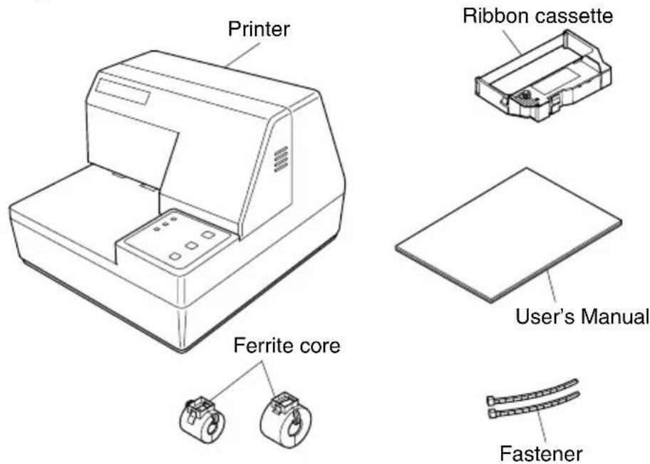
text_image
Printer Ferrite core Ribbon cassette User's Manual FastenerIf anything is missing, contact the dealer where you bought the printer and ask them to supply the missing part. Note that it is a good idea to keep the original box and all the packing materials just in case you need to pack the printer up again and send it somewhere at a later date.
Removing the protective materials
Four protective materials are inserted into the printer to protect components during shipping. Before using the printer, be sure to remove all protective materials as shown in the illustration.
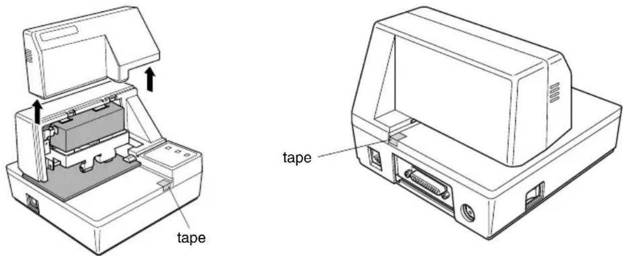
text_image
tape tapeGeneral guide
The following illustrations describe the major components, buttons, and connectors of your printer.
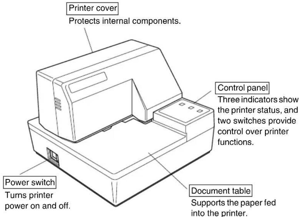
text_image
Printer cover Protects internal components. Control panel Three indicators show the printer status, and two switches provide control over printer functions. Power switch Turns printer power on and off. Document table Supports the paper fed into the printer.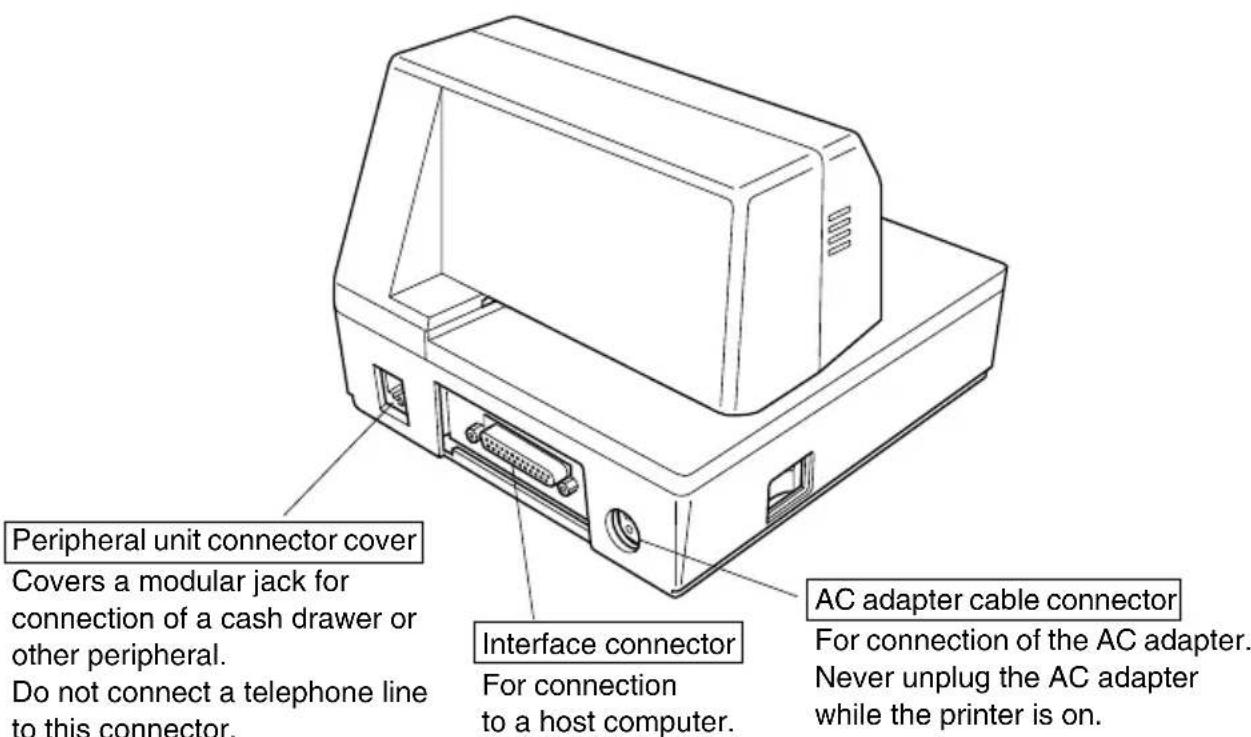
text_image
Peripheral unit connector cover Covers a modular jack for connection of a cash drawer or other peripheral. Do not connect a telephone line to this connector. Interface connector For connection to a host computer. AC adapter cable connector For connection of the AC adapter. Never unplug the AC adapter while the printer is on.Removing the printer cover
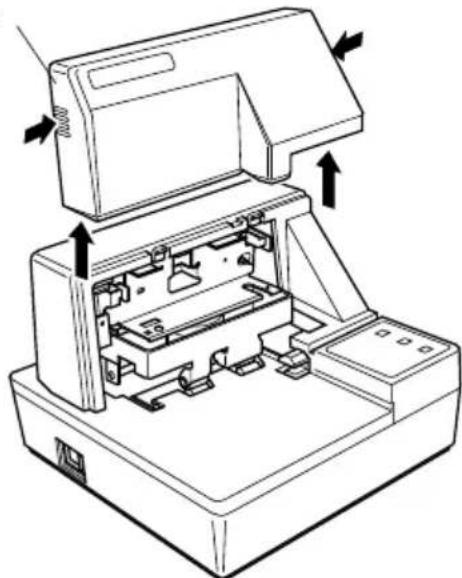
☐ Push straight up on the ridged locations on the sides of the printer cover to remove it from the printer.
Printer cover
natural_image
Technical line drawing of a printer internal structure with arrows indicating assembly or movement (no text or symbols present)☐ To replace the cover, slide it back down into position. Gently press down on the cover until you hear it click securely into place.
Installing the ribbon cassette
Make sure that the printer's paper release is activated (the paper is not held in place by the paper feed roller). If it cannot be determined whether or not the paper release is activated, turn on the printer and check if the RELEASE indicator on the control panel is lit. If the indicator is not lit, press the RELEASE button until the indicator lights up.
☐ Make sure that the printer is turned off and unplugged from its power outlet.
Remove the printer cover.
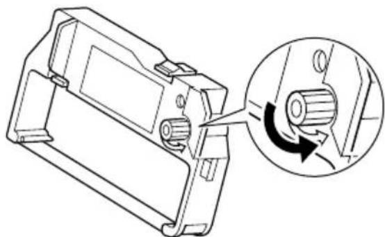
☐ Remove the ribbon cassette from its packaging, and turn its knob in the direction indicated by the arrow to take up any slack in the ribbon.
natural_image
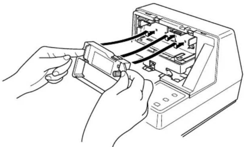
Technical line drawing of a mechanical component with a magnified inset showing rotational direction (no text or symbols)☐ Holding the ribbon cassette so that the ribbon is facing down, install the cassette into the slip printer as shown in the illustration.
natural_image
Line drawing of hands inserting a component into an open computer case (no text or symbols)☐ Press gently but firmly on the cassette until it snaps securely into place.
☐ Rotate the knob on the cassette again to take up any slack.
Replace the printer cover.
Important!
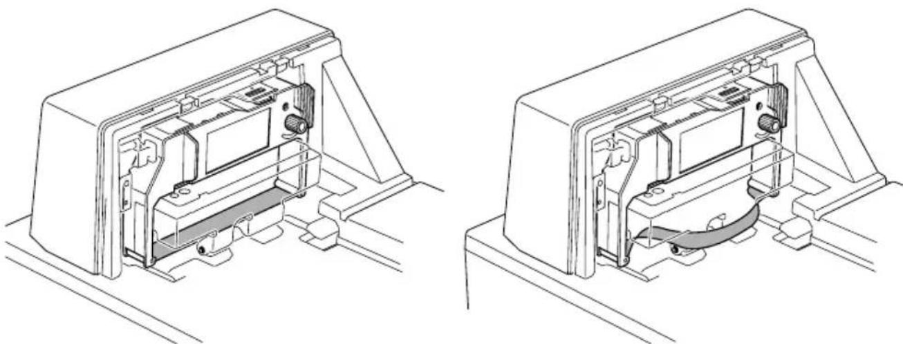
Make sure that the ribbon is not twisted before installing the ribbon cassette. Otherwise, the ribbon may become jammed in the printer and damage the ribbon rollers.
natural_image
Technical line drawings of two views of a device housing or enclosure, showing internal components and mounting brackets (no text or symbols)In addition, if the ribbon becomes twisted after installation, remove the ribbon cassette, untwist the ribbon, and then reinstall the cassette.
Removing the ribbon cassette
Use the following procedure to remove the ribbon cassette from the slip printer when you want to replace it with a new one.
☐ Make sure that the printer is turned off and unplugged from its power outlet.
Remove the printer cover.
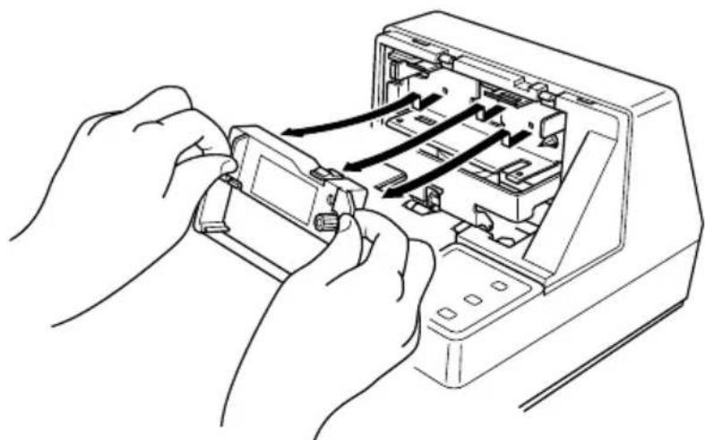
☐ Grasping the ribbon cassette as shown, gently pull it away from the printing mechanism.
natural_image
Line drawing of hands inserting or adjusting a device into an open computer case (no text or symbols visible)☐ Use the procedure under “Installing the ribbon cassette” on page 4 to install a new cassette.
Connecting to a power outlet and turning power on and off
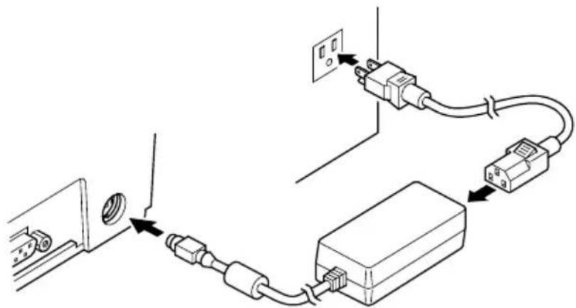
Plug the AC adapter that comes with the printer into the printer's AC adapter cable connector.
☐ Connect a three-prong grounded power cord to the power cord connector of the AC adapter.
Note:
The printer does not come with a power cord, so you must provide one yourself.
☐ Plug the other end of the power cord to a standard household wall outlet.
text_image
Diagram showing cable connection to a device with labeled components and wiring paths☐ Use the power switch on the left side of the printer to turn power on and off.

natural_image
Simple line drawing of a rectangular object with a circular hole and a curved edge (no text or symbols)Important!
We recommend that you unplug the printer from the power outlet whenever you do not plan to use it for long periods. Because of this, you should locate the printer so that the power outlet it is plugged into is nearby and easy to access.
At this point you may want to perform a test of the printer to make sure it is working properly. See page 15 for details on how to test the printer.
Connecting to your host computer
The computer sends data to the printer through a cable to the printer's interface (Serial Interface Connector Type: D-sub 25-pin or Parallel Interface Connector Type: 36-pin Centronics compatible). This printer does not come with a cable, so it is up to you to obtain one that suits your needs.
Important!
- The following instructions apply to the cable that is used with an IBM-compatible personal computer. Note that they do not apply to all types of computers and cables. If you are unsure about what type of cable you should use to connect with your computer, consult your dealer.
- Make sure that the printer is turned off and unplugged from the AC outlet and that the computer is turned off before connecting them.
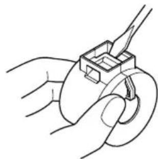
☐ Affix the larger ferrite core onto the cable as shown in the illustration below.
natural_image
Line drawing of hands holding a small mechanical component (no text or symbols)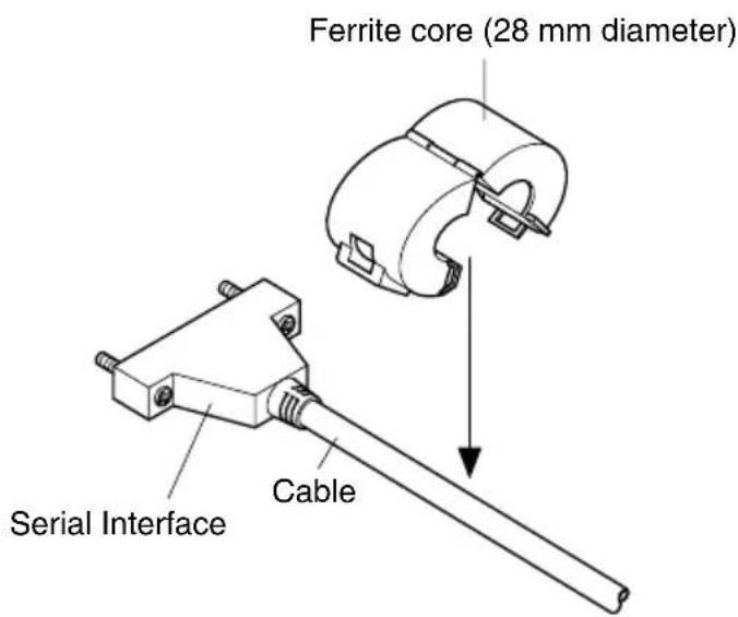
text_image
Ferrite core (28 mm diameter) Serial Interface CablePass the fastener through the ferrite core.
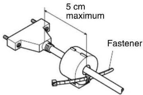
text_image
5 cm maximum FastenerLoop the fastener around the cable and lock it. Use scissors to cut off any excess.
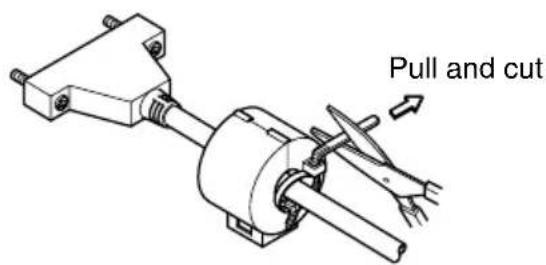
text_image
Pull and cutFor a serial cable:
☐ Plug one end of the serial cable into the serial port of your computer, and the other end of the cable into the socket on the back of the printer. Secure both connectors in place with the screws that are provided.
For a parallel cable:
☐ Attach a ferrite core in the same way that one is attached to a serial cable.
☐ Plug one end of the parallel cable into the parallel port of your computer. The parallel port should be labeled “Printer”, “Parallel”, “PRN”, “LPT1” or something similar.
☐ Plug the other end of the parallel cable into the socket on the side of the printer and secure it in place with the clips.
Connecting to a peripheral unit
You can connect a peripheral unit to the printer using a modular plug. The following describes how to install the ferrite core and make the actual connection. See “Modular plug” on page 137 for details about the type of modular plug that is required. Note that this printer does not come with a modular plug or wire, so it is up to you to obtain one that suits your needs.
Important!
Make sure that the printer is turned off and unplugged from the AC outlet and that the computer is turned off before making connections.
☐ Affix the smaller ferrite core onto the modular wire as shown in the illustration below.
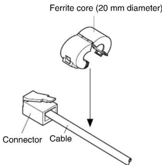
text_image
Ferrite core (20 mm diameter) Connector CablePass the fastener through the ferrite core.
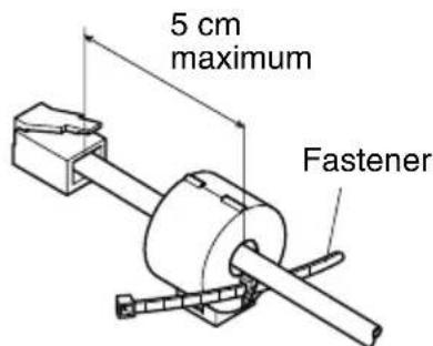
text_image
5 cm maximum FastenerLoop the fastener around the cable and lock it. Use scissors to cut off any excess.
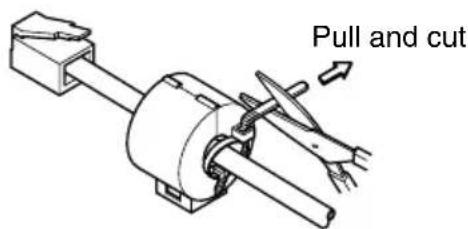
text_image
Pull and cut☐ Plug one end of the modular cable into the modular jack of the peripheral.
☐ Remove the modular jack cover from the back of the printer and plug the other end of the modular cable into the jack of the printer.
Inserting the paper into the printer
Use only the specified type of paper for this printer. Do not use inappropriate types of paper, or it could cause malfunction or damage of the printer.
The following procedure describes how to print on paper. Before trying to print, be sure to install a ribbon cassette into the printer using the procedure under “Installing the ribbon cassette” on page 4.
☐ Make sure that the printer is plugged in and turned on.
☐ Check that the RELEASE indicator on the control panel is lit. If the indicator is not lit, press the RELEASE button until the indicator lights up.
Important!
Insertion and removal of paper should be done only when the printer is released condition (the paper is not held by paper feed roller).
Place a piece of the paper onto the printer's document table and slide its right edge into the printer. Printing will be performed on the side of the paper that is facing up (the one you can see), starting from the top of the paper.
Important!
Do not use wrinkled or curled paper. In case of multiple paper, neatly align the sheets.
Though paper can be inserted either from the front or side of the printer, front paper insertion may result in paper jams, depending on the condition of the paper. Because of this, it is recommended that you always insert paper from the side.
AutoSide Loading™
This printer is equipped with paper sensors, so you do not have to perform any special procedure to align the location from which printing should start. Simply insert the paper into the printer and the sensor locates the top of the paper. The paper will be moved automatically into position for printing.
Important!
When inserting the paper into the printer, make sure that there are at least 3 cm between the top edge of the paper and the print start position mark on the printer. Otherwise the paper sensor may not be able to correctly locate the top of the paper.
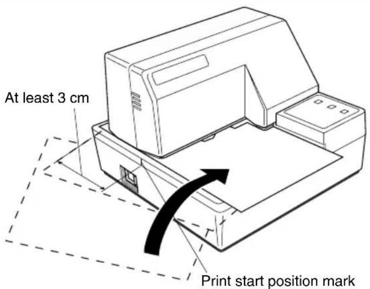
text_image
At least 3 cm Print start position mark☐ Push the right edge of the paper into the printer until it stops. At that time, the PAPER OUT indicator will go out, and the printer mechanism will automatically align the paper for printing from the top.
☐ Send data from your host computer to be printed on the paper.
☐ After printing, press the RELEASE button to automatically release the paper.

natural_image
Line drawing of a laboratory instrument with a tray and base (no text or symbols)Chapter 2: Control Panel Operations
The control panel gives you some push-button control over the slip printer operation. It also includes indicator lights, which tell you the current status of the printer at a glance.
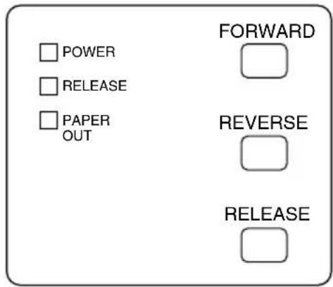
text_image
POWER RELEASE PAPER OUT FORWARD REVERSE RELEASEIndicator lights
The following table describes the meaning of indicator lights when it is on, off, or flashing.
| Indicator Light Off | On Flashing | ||
| POWER | Power off Power on | Dot Alignment Adjust Mode | |
| PAPER OUT | Paper inserted No paper insert paper prompt | ||
| RELEASE | Slip paper engaged Slip paper released Mechanical error | ||
Buttons
The following table describes the function of the three control buttons of the control panel.
| Button Description | |
| FORWARD | Feeds the slip paper forward, toward the back of the printer. One press feeds one line, holding down performs continuous feed. |
| REVERSE | Feeds the slip paper back, toward the front of the printer. One press feeds one line, holding down performs continuous feed. |
| RELEASE | Activates the printer's paper release (the paper is not held in place by the paper feed roller).Clears recoverable errors. |
Producing a test print
The following procedure can be used at any time to test the printer.
☐ Turn on the printer and insert a piece of paper (page 6, 11).
Turn off printer power.
☐ While holding down RELEASE, turn printer back on. Keep RELEASE depressed for a few moments until the printer beeps and the printer test print starts.
The printer test will continue until it reaches the end of the paper.
Adjusting the dot alignment
You may never have to use the procedure described in this section, but after you have been using your printer for some time you may find that the dots of some graphics do not align correctly. For example, what should look like:

may come out looking like one of the following:

or like this

This is caused when mechanical parts of the printer get out of alignment. This happens only rarely and you may never experience it at all throughout the life of the printer. If you do have problems, use the following procedure to correct it.
☐ Turn on the printer and insert a piece of paper.
Turn off printer power.
While holding down the control panel's FORWARD and REVERSE buttons, turn the printer back on to enter the Dot Alignment Adjust Mode, which is indicator by a flashing POWER indicator flashes.
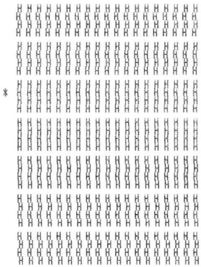
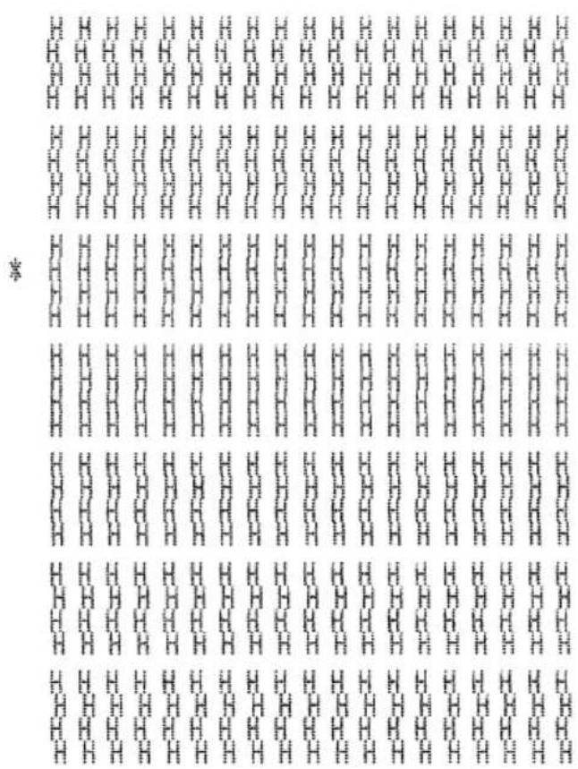
Entering the Dot Alignment Adjust Mode causes seven blocks to be printed, each of which indicates a dot alignment setting, as shown below. An asterisk to the left of the blocks indicates which block is currently selected.
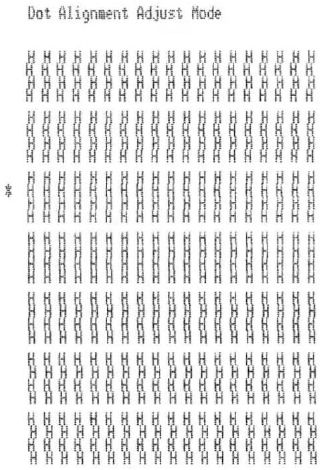
text_image
Dot Alignment Adjust Mode *☐ Use FORWARD to specify the block that appears to have the best aligned characters. Press FORWARD once to specify the first block, twice to specify the second block, and so on up to seven times to specify the seventh block.
Warning beep will sound if you press FORWARD more than seven times.
☐ After specifying a block, press REVERSE to register your selection and exit the Dot Alignment Adjust Mode.
The dots alignment adjustment setting you selected is stored in printer memory and a pattern is printed using the selected setting followed by the message “Adjust Complete!” The printer ejects the paper after printing is complete.
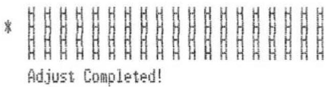
text_image
* Adjust Completed!Note:
You setting is not registered if you turn off printer power before pressing REVERSE to exit the Dot Alignment Adjust Mode. If a paper feed error occurs during this mode, the printer ejects the paper and this mode is cancelled.
Hexadecimal dump
This procedure prints in hexadecimal format all codes (character codes and control codes) that are sent to the printer by the computer. The printer does not execute any control codes (such as 0A - linefeed), it just prints them out. The hexadecimal dump is useful when you are writing programs for printer control.
Turn on the printer and insert a piece of paper.
Turn off printer power.
While holding down the control panel's FORWARD buttons, turn the printer back on to enter the Hex Dump Mode.
☐ To exit the Hex Dump Mode, turn the printer off.
Note:
The printer will not responde to any commands you send it while it is in the Hex Dump Mode.
Errors
There are three types of errors: recoverable errors that require some action by you before they clear, non-recoverable errors that require servicing by an authorized service provider, and a data receive error. Errors are indicated by and audible buzzer and the indicators.
Recoverable Errors
| Error Type | Indicators | Recovery | ||
| POWER RELEASE PAPER OUT | ||||
| Paper jam | Flashing | Correct the cause of the problem and then press RELEASE. | ||
| Carriage motor lockup | ||||
| Abnormal home position signal | ||||
| Abnormal timing signal | ||||
Non-recoverable Errors
| Error Type | Indicators | Recovery | ||
| POWER RELEASE PAPER OUT | ||||
| RAM read/write | Off On On | Turn off the printer, then after waiting a few minutes, turn the printer back on. If the printer does not recover, contact your nearest service provider. | ||
| CPU lockup | ||||
Data Receive Error
This type of error is caused whenever a problem is encountered during data receipt. The method used by the printer to recover from a data receive error depends on the current command mode.
| Command mode Data Receive Error Recover Procedure | |
| Star mode The printer prints a question mark. | |
| ESC/POS mode | Memory switch 4-0=0 : The printer prints a question mark.Memory switch 4-0=1 : The printer discards the received data. |
Paper Sensors
The following paper sensors are available.
TOF Sensor
This top-of-form sensor detects the leading edge of the paper.
When enabled, the TOF sensor detects when there is no paper present and stops printing.
BOF Sensor
This bottom-of-form sensor detects the trailing edge of the paper. When enabled, the BOF sensor detects when there is no paper present and printing is interrupted.
When the TOF or BOF sensor detects that no paper is present, the printer stops its motor after printing of 0 to a maximum of two more lines.
The BOF sensor detects a paper out condition whenever the distance between print head pin #9 and the trailing edge of the paper becomes 38.1 mm or less. In the Star Mode, this enters the print stop operation, but in the ESC/POS Mode, the print stop operation is not entered until the distance between print head pin #9 and the trailing edge of the paper becomes 27.3 mm or less.
When the auto clamp is enabled with Memory Switch 5-1, the auto clamp operation is performed about 0.7 second (initial default in Star Mode; ESC/POS Mode initial value is approximately 1 second) after the presence of paper is detected both by the TOF and BOF sensors, following a paper out condition. The auto clamp function is not affected by whether the TOF or BOF sensor is enabled or disabled.
The top of form positioning function is enabled with Memory Switch 5-0. Even if the auto clamp function is disabled, auto top of form positioning is performed if the paper is clamped when printing starts.
The PAPER OUT lamp flashes to request insertion of paper when the sensors detect there is no paper (when a sensor enabled by command detects no paper) after data is received by the printer. At that time, the user inserts paper, and printing begins after the sensor detects that paper is present.
Chapter 3: Command Summary
This printer supports two different command modes: the Star mode and the ESC/POS mode.
The Star mode emulates previous Star printers. The ESC/POS mode emulates the Epson TM-295 or TM-290 slip printer.
This chapter provides you with all of the commands supported by this printer.
Important!
Access the following URL for the latest version of this manual and for updates on supported commands: http://www.star-micronics.co.jp/service/sp_sup_e.htm
Star Mode Commands
The following tables show the Star mode commands that are supported by this printer.
Character Selection
| Control Codes | Hexadecimal Codes | Function |
| “R” n | 1B 52 n | |
| “/” “1” | 1B 2F 31 | |
| “/” <1> | 1B 2F 01 | |
| “/” “0” | 1B 2F 30 | |
| “/” <0> | 1B 2F 00 | |
| “t” n | 1B 1D 74 n | |
| “M” 1B 4D Selects the 7 | ||
| “P” 1B 50 Selects the 5 | ||
| “:” 1B 3A Selects the 5 | ||
| n | 1B 20 n | |
| 0E Sets the printing magnified double in character width | ||
| 14 Resets the printing magnified in character width | ||
| "W" n | Sets the magnification rate in character width | |
| "h" n | Sets the magnification rate in character height | |
| “-” “1” | Selects underlining | |
| “-” <1> | 1B 2D 31 | |
| “-” “0” | 1B 2D 30 | |
| “-” <0> | 1B 2D 00 | |
| “_” “1” | 1B 5F 31 | |
| “_” <1> | 1B 5F 01 | |
| “_” “0” | 1B 5F 30 | |
| “_” <0> | 1B 5F 00 | |
| “4” 1B 34 Selects highlight printing | ||
| “5” 1B 35 Cancels unhighlight printing | ||
| 0F | Inverted printing | |
| 12 Cancels inverted printing | ||
| “i” “0” | 1B 1E 96 30 | |
| “i” <0> | 1B 1E 96 00 | |
| “i” “1” | 1B 1E 96 31 | |
| “i” <1> | 1B 1E 96 01 | |
| “i” “2” | 1B 1E 96 32 | |
| “i” <2> | 1B 1E 96 02 | |
| “E” 1B 45 Selects emphasized printing | ||
| “F” | 1B 46 | |
| “U” n | 1B 55 n | |
Print Position Control
| Control Codes | Hexadecimal Codes | Function |
| 1B 61 n | Feeds paper n lines | |
| 09 | Horizontal tab | |
| 1B 41 n | Defines n/72-inch line spacing | |
| n/72-inch line spacing | ||
| 1B 7A 30 | Sets line spacing to 1/12-inch | |
| 1B 7A 00 | ||
| 1B 7A 31 | Sets line spacing to 1/6-inch | |
| 1B 7A 01 | ||
| 1B 4A n | One time n/72-inch feed | |
| 1B 6A n | One time n/72-inch backfeed | |
| 1B 33 n | Sets line spacing to n/216-inch approximately | |
| n | Sets line spacing to n/144-inch | |
| n1 n2 ... 00 Sets horizontal tab stops | ||
| 1B 6C n | Sets left margin | |
| 1B 51 n | Sets right margin | |
| 1B 1D 61 30 | Left justification (Default) | |
| 1B 1D 61 00 | ||
| 1B 1D 61 31 | Centering | |
| 1B 1D 61 01 | ||
| 1B 1D 61 32 | Right justification | |
| 1B 1D 61 02 | ||
Dot Graphics Control
| Control Codes | Hexadecimal Codes | Function |
| “K” n <0> m1 m2 ... | 1B 4B n 00 m1 m2 ... | 8 dot normal density graphics |
| “L” n1 n2 m1 m2 ... | 1B 4C n1 n2 m1 m2 ... | 8 dot high density graphics |
Download Graphics Printing
| Control Codes | Hexadecimal Codes | Function |
| 00 n1 n2 .. Defines download characters | ||
| 1B 25 31 | Enables download character set | |
| 1B 25 01 | ||
| 1B 25 30 | Disables download character set | |
| 1B 25 00 | ||
Peripheral Device Control
| Control Codes | Hexadecimal Codes | Function |
| 1B 07 n1 n2 | Defines drive pulse width for peripheral device #1 | |
| device #1 | ||
| device #1 immediately | ||
| device #2 immediately | ||
| device #2 immediately |
Slip Control
| Control Codes | Hexadecimal Codes | Function |
| 1B 0F n | Setting slip sensor | |
| 1B 0C n | Slip function | |
| 1B 0B m n | Sets the paper eject direction/length | |
| 1B 19 n m 0A 00 Sets | the wait time until the automatic clamp is activated |
Page mode
| Control Codes | Hexadecimal Codes | Function |
| “n” 1B 6E Selects page mode | ||
| “!” 1B 21 Selects line mode | ||
| “*” ... | Setting print area in page mode | |
| “T” n | Setting print direction in page mode | |
| 0C Prints in page mode |
Other Commands
| Control Codes | Hexadecimal Codes | Function |
| 18 Cancels printer buffer & Initialize printer | ||
| “#N, n1 n2 n3 n4” | Sets memory switch | |
| 1B 23 N 2C n1 n2n3 n40A 00 | ||
| “@” 1B 40 Initialize printer | ||
| Transmits EOT status | ||
| 05 | Transmits ENQ status | |
| 17 | Confirms finish of printing | |
| Transmits automatic status | ||
| IB IE 61 n Enables/disables automatic status | ||
| 1B 3F 0A 00 | Resets printer hardware and produce a test print |
ESC/POS Mode Commands (TM-295 emulation)
The following table lists the TM-295 emulation commands that are supported by this printer.
| Control Codes | Hexadecimal Codes | Function |
| Paper eject in single sheet modePaper mode print and return | ||
| 10 04 Enables real-time status send (Serial I/F only) | ||
| SP 1B 20 Sets size of space to right of character | ||
| ! 1B 21 Enables batch print mode | ||
| # 1B 23 Sets memory switch | ||
| % 1B 25 Enables/disables download character set | ||
| & 1B 26 Defines download character | ||
| * 1B 2A Selects bit image mode | ||
| 2 | 1B 32 Selects 1/6-inch line spacing | |
| 3 | 1B 33 Selects approximate n/60-inch line spacing *1 | |
| = | 1B 3D | Selects peripheral device |
| @ | 1B 40 Initializes the printer | |
| C | 1B 43 Sets the eject length for single-sheet printing | |
| D | 1B 44 Sets horizontal tab position | |
| F | 1B 46 Enables/disables reverse feed for single-sheet mode | |
| J | 1B 4A Prints and | n/60-inch (approximate value) paper feed *1 |
| K 1B 4B Prints and | n/60-inch (approximate value) reverse paper feed *1 | |
*1: n/60-inch line spacing and paper feed commands: Since the minimum paper feed pitch for this printer is 1/144 inch, n/60 inch can considered an approximate value. However, the actual value is INT ((6n/5) + 0.5)/72 inch.
| Control Codes | Hexadecimal Codes | Function |
| L 1B 4C Selects page mode | ||
| R 1B 52 Selects international character set | ||
| T 1B 54 Selects direction for page mode character printing | ||
| U 1B 55 Selects print direction | ||
| V 1B 56 Designates/cancels 90° character rotation | ||
| W 1B 57 Sets print area for page mode printing | ||
| a 1B 61 Aligns position | ||
| c3 1B 63 33 | ||
| c4 1B 63 34 Selects the paper-end sensor for stopping printing | ||
| c5 1B 63 35 Enables/disables control panel switches | ||
| d 1B 64 Prints or feeds | ||
| e 1B 65 Prints or reverse feeds | ||
| f 1B 66 Sets single-sheet wait time | ||
| p 1B 70 Generates specified pulse | ||
| q 1B 71 Release | ||
| t 1B 74 Selects character code table | ||
| u 1B 75 Sends peripheral status (Serial I/F only) | ||
| v 1B 76 Sends paper sensor status (Serial I/F only) | ||
| { 1B 7B Enables/disables inverted printing | ||
| I 1D 49 Sends printer ID (Serial I/F only) | ||
| a 1D 61 | ||
| r | 1D 72 Sends printer status (Serial I/F only) |
ESC/POS Mode Commands (TM-290 emulation)
The following table lists the TM-290 emulation commands that are supported by this printer.
| Control Codes | Hexadecimal Codes | Function |
*1: n/60-inch line spacing and paper feed commands: Since the minimum paper feed pitch for this printer is 1/144 inch, n/60 inch can considered an approximate value. However, the actual value is INT ((6n/5) + 0.5)/72 inch.
| Control Codes | Hexadecimal Codes | Function |
| R 1B 52 Selects international character set | ||
| Selects the paper-end sensor for sending the no-paper signal | ||
| c4 1B 63 34 Selects the paper-end sensor for stopping printing | ||
| c5 1B 63 35 Enables/disables control panel switches | ||
| d 1B 64 Prints or feeds | n lines | |
| h 1B 68 Sets/Cancels reverse line feed | ||
| j 1B 6A Selects character width in vertical printing mode | ||
| q 1B 71 Release | ||
| t 1B 74 Selects character code table | ||
| v n | Requests paper sensor status (Serial I/F only) | |
| { 1B 7B Enables/disables inverted printing | ||
| J 1C 4A Sets vertical printing mode | ||
| K 1C 4B Cancels vertical printing mode | ||
| W 1C 57 Sets/Cancels double-height, double-width printing |
TABLE DES MATIÈRES
natural_image
Technical line drawing of a mechanical component with a magnified inset showing rotational motion (no text or symbols)natural_image
Line drawing of hands inserting or connecting a device into an open computer case (no text or symbols visible)natural_image
Technical line drawing of a mechanical device interior showing internal components (no text or symbols)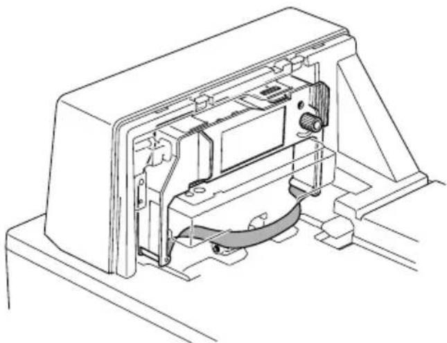
natural_image
Technical line drawing of an internal mechanical assembly (no text or symbols)natural_image
Line drawing of hands inserting or adjusting a device into an open computer case (no text or symbols visible)text_image
Diagram showing cable connection to a device with labeled components and wiring pathsnatural_image
Simple line drawing of a door handle with a circular knob and a curved handle (no text or symbols)Attention!
natural_image
Line drawing of hands holding a circular object with a mechanical component attached (no text or symbols)natural_image
Line drawing of a laboratory instrument with a tray and base (no text or symbols)text_image
Dot Alignment Adjust Mode *text_image
* Adjust Completed!Remarque:
text_image
Klebeband Klebebandnatural_image
Technical line drawing of an open printer with internal components and directional arrows indicating assembly (no text or symbols)natural_image
Technical line drawing of a mechanical component with a magnified inset showing rotational direction (no text or symbols)natural_image
Line drawing of hands inserting or connecting a device into an open computer case (no text or symbols visible)natural_image
Technical line drawing of an internal electronic device housing (no text or symbols)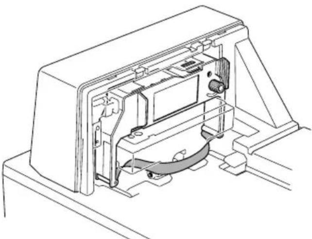
natural_image
Technical line drawing of an internal mechanical or electronic component with no visible text or symbolsnatural_image
Line drawing of hands inserting or adjusting a device into an open computer case (no text or symbols visible)text_image
Diagram showing cable connection between a device and two connected devices with labeled componentsnatural_image
Simple line drawing of a door handle with a circular opening and a curved handle (no text or symbols)Wichtig!
natural_image
Line drawing of hands holding a small mechanical component (no text or symbols)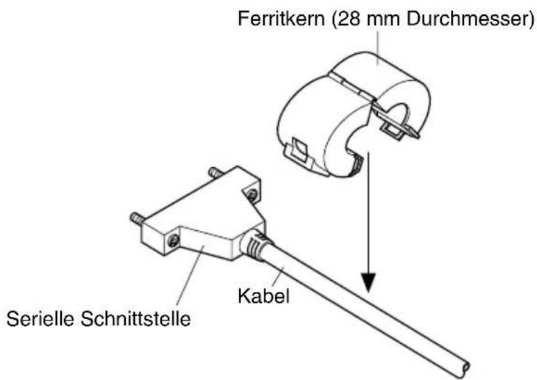
text_image
Ferritkern (28 mm Durchmesser) Kabel Serielle Schnittstellenatural_image
Line drawing of a laboratory instrument with a tray and base (no text or symbols)Dot Alignment Adjust Mode
text_image
Image showing a grid of identical rectangular patterns with repeated 'x' marks, likely representing a pattern or symbol.text_image
* Adjust Completed!Hinweis:
natural_image
Technical line drawing of an open industrial machine with internal components and directional arrows indicating assembly (no text or symbols)natural_image
Technical line drawing of a mechanical component with a magnified inset showing rotational motion (no text or symbols)natural_image
Line drawing of hands inserting or connecting a device into an open computer case (no text or symbols visible)natural_image
Technical line drawing of a mechanical device interior showing internal components (no text or symbols)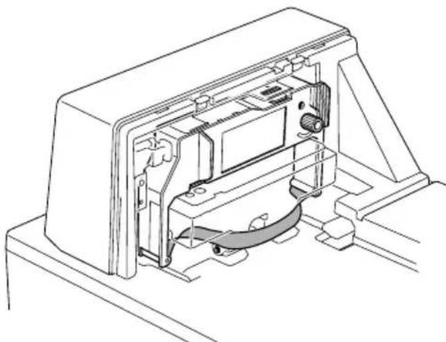
natural_image
Technical line drawing of an internal electronic device with visible ports and wiring (no text or symbols)natural_image
Line drawing of hands inserting or adjusting a device into an open computer case (no text or symbols visible)text_image
Diagram showing cable connection to a device with labeled components and wiring pathsnatural_image
Simple line drawing of a rectangular box with a circular hole and a curved handle (no text or symbols)Importante!
natural_image
Line drawing of hands holding a small mechanical component (no text or symbols)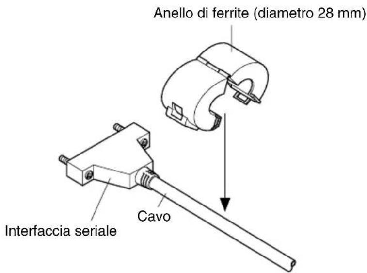
natural_image
Line drawing of a laboratory instrument with a tray and base (no text or symbols)Dot Alignment Adjust Mode
text_image
Image showing a grid of identical rectangular patterns with repeated 'X' symbols, likely representing a pattern or data visualization.text_image
* Adjust Completed!Nota:
General Specifications
Printing System Serial impact dot-matrix
Number of Head Pins 9 wires
Printing Speed 3.1 lines/sec maximum
Number of Print Columns 42
Dot spacing Horizontal: 0.30mm
Vertical: 0.35mm
Paper Width 80mm to 182mm
Sensors Paper out top-of-form, bottom-of-form sensors
Command Modes Star mode
ESC/POS mode (TM-295 emulation)
ESC/POS mode (TM-290 emulation)
Interface Serial (RS-232C standard)
Parallel (centronics compatible)
Data Buffer Star mode: 2 K bytes / 35 bytes
ESC/POS mode: 512 bytes / 35 bytes
Reliability Mechanism (MCBF): 2.5 million lines
Printer head life: 70 million characters
Operating Environment
| Temperature | 41°F to 104°F (5°C to 40°C) |
| Humidity | 10% to 80% RH at 40°C (non-condensing) |
Storage Environment
| Temperature | -4^ to 140^ ( -20^ to 60^ ) |
| Humidity | 5% to 90% RH at 40^ (non-condensing) |
Ink Ribbon
| Type | Cartridge cassette |
| Color Black | |
| Ribbon Material | Nylon # 66 denier |
| Life | 1.5 million characters |
Important!
Use only the specified type of ribbon. Use of another type of ribbon can cause malfunction of and damage to the printer.
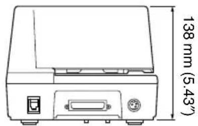
Dimensions and Weight
Dimensions 180 (W)
×190 (D) ×138 (H) mm / 7.09" × 7.48" × 5.43"
Weight 2.1 kg / 4.6 lbs.
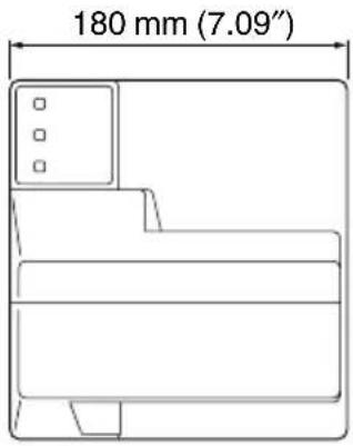
text_image
180 mm (7.09")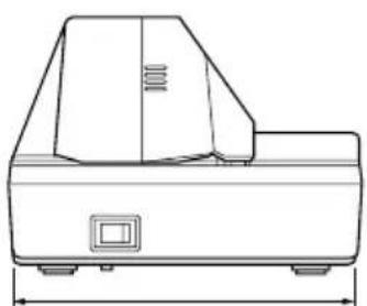
natural_image
Technical line drawing of a mechanical device with dimension lines (no text or symbols)190 mm (7.48")
text_image
138 mm (5.43")Printing Specifications
Printing Width
63mm
Character Set
Star Mode ASCII : 96 / Block Graphics : 64 / Special : 64 / Katakana : 64 / IBM Special : 64 / IBM
Block Graphics : 50 / International :11 / Slashed Zero / Code Page 858 / Code Page 852
/ Code Page 860 / Code Page 861 / Code Page 863 / Code Page 865 / Code Page 866
ESC/POS Mode Page 0 (PC 437) / Page 1 (Katakana) / Page 2 (PC 858) / International / Slashed Zero
Character Matrix
Star Mode 7
× 9 (half), 42 columns
5 × 9, 35 columns
IBM block graphics are 12 dots high.
ESC/POS Mode 7
× 9 (half), 42 columns
5 × 9, 35 columns
Character Dimensions
7×9 font (half): 1.2 (W)×2.42 (H) mm
5×9 font (2 pulses per dot): 1.5 (W) × 2.42 (H) mm
5×9 font (3 pulses per dot): 2.1 (W) × 2.42 (H) mm
Paper Specifications
| Paper Width | 80 to 182mm / 3.15" to 7.17" | |
| Paper Length | 80 to 257mm / 3.15" to 10.8" | |
| Copies | Original + 2 | |
| Paper Thickness | 1-ply: 0.09 to 0.2mm / 0.0035" to 0.0079"Duplicates 0.12 mm (minimum for 2-ply forms) to 0.25 mm/0.0047 " to 0.0098"Maximum 0.2 mm when printing graphics> | |
| Copy Offset | 1.5mm maximum/15 lines (between top sheet and bottom sheet) | |
| Binding | Top or left |
Print Area
Distance from first printed line (Head #1) to top of form (form stopper): 28.6 mm
Distance from first printed line (Head #1) to TOF sensor: 26.0 mm
(However, with the automatic start position operation, this distance is set to 26.5 mm.
The automatic start position operation can be enabled or disabled with the memory switches.
When the top-of-form sensor is disabled, a command can be used to perform a reverse paper feed enabling printing to begin at approximately 20 mm from the top of the paper.)
Distance from last printed line (Head #9) to bottom of form (BOF sensor): 38.1 mm
(With the ESC/POS mode, printing may continue to 27.3 mm from the bottom of the paper.)
When the BOF sensor is disabled, printing can continue to 14.0 mm from the bottom of the paper.
Right margin: 5.1 mm
Print area width: 28.6 mm
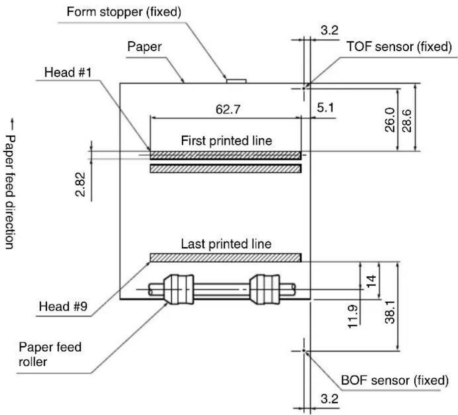
text_image
Form stopper (fixed) Paper 3.2 TOF sensor (fixed) Head #1 62.7 5.1 26.0 28.6 First printed line 2.82 Paper feed direction Last printed line Head #9 14 11.9 38.1 Paper feed roller BOF sensor (fixed) 3.2Units: mm
Print Position

text_image
Paper feed direction 8 mm No holes in this areaDo not use paper with perforations within the shaded area. Perforations may cause the paper sensor to erroneously report an out of paper condition.
Paper Feed
Drive Stepping motor
Pitch Star Mode: Adjustable in 1/144
"units
ESC/POS Mode: Adjustable in n/60" units (approximate)
Speed (while printing) 3.5
"per second
Speed (while ejecting) 4.5
"per second
Important!
Slip paper must be flat, smooth, and free of curls, bends, wrinkles and folds, all of which can cause jamming and soiling by ink.
Power Supply Specifications
Power Supply
AC Adaptor PS60A-24 series, switching type
Input 90 to 264V AC, 50/60Hz
Output 24V DC ± 5%, 2.0A
Plug 3-pin POWER JACK TCP 8927 (Hoshiden brand or equivalent.)
Consumption Current
| Conditions: 24V, excluding external equipment driving | |
| Operating (approximate averages) | Continuous ASCII printing + paper feed: 0.6A Solid block printing + paper feed: 1.0A Solid block printing: 1.9A Peak (solid printing): 3.1A |
| Stand-by (approximate averages) | Paper release deactivated: 0.24 A Paper release activated: 0.07A |
Important!
- When using a printer power supply other than the optional AC adaptor (PS60A-24 series), be sure that the following cautions are observed.
- Use a power supply of DC 24 V ±5% and more than 2.0 A.
- Be careful about installing the printer in an area where there is noise. Take the appropriate measures to protect against electrostatic AC line noise, etc.
- The optional cable set can be connected.
Appendix B: Making DIP Switch Settings
The printer's DIP switches let you specify communications parameters, receive buffer size, and emulation. This Appendix explains the settings you can make and tells you how to actually change DIP switch settings.
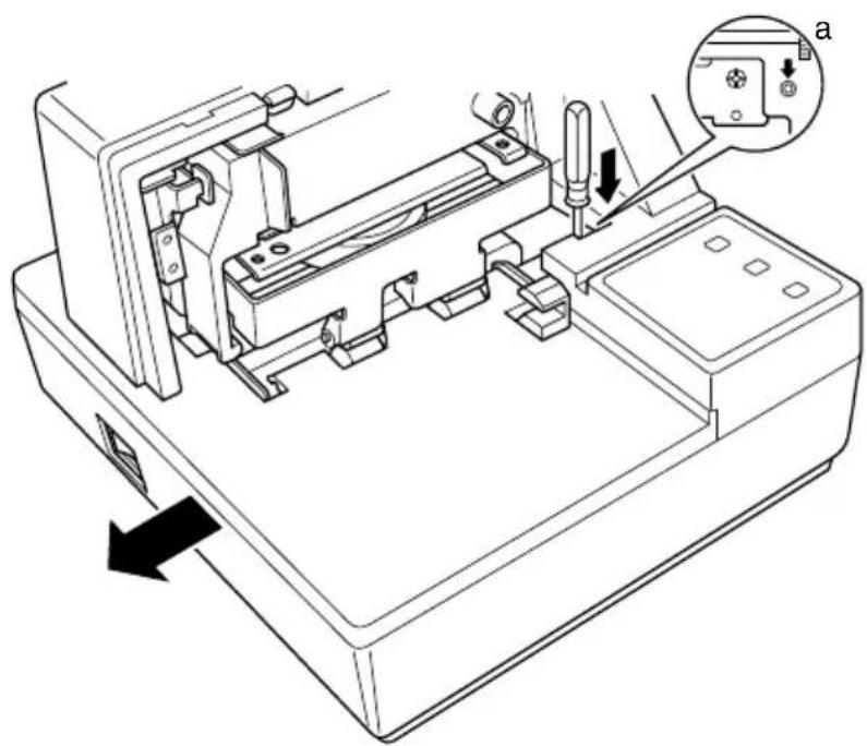
Accessing the DIP switches
The DIP switches are located inside the printer, underneath the document table. Use the following procedure to remove the document table so you can operate the DIP switches.
☐ Make sure that the printer is turned off and unplugged from its wall outlet.
☐ Remove the printer cover.
☐ While using a screwdriver or other similar instrument to press down at the location marked (a) in the illustration below, carefully slide the document table in the direction indicated by the arrow until it is out of the way.
natural_image
Technical line drawing of a mechanical assembly with a tool inserted, showing internal components and a directional arrow (no text or symbols)It is not necessary to remove the document table completely, just move it enough so you can get at the DIP switches inside.
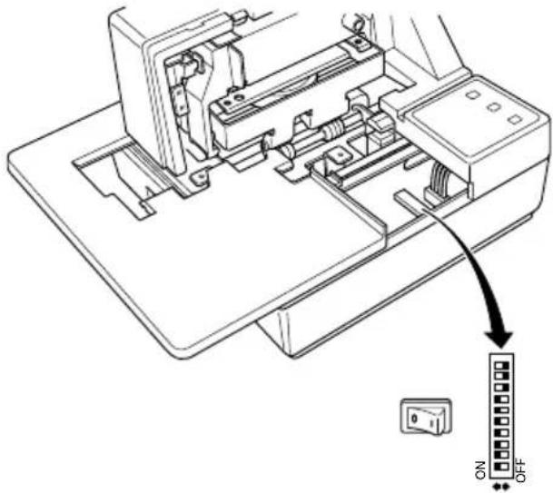
text_image
Technical diagram of a printer internal structure with an arrow pointing to a control panel labeled 'ON' and 'OFF'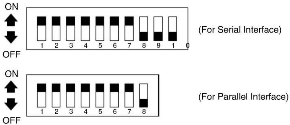
text_image
ON ↑ ↓ OFF 1 2 3 4 5 6 7 8 9 1 0 (For Serial Interface) ON ↑ ↓ OFF 1 2 3 4 5 6 7 8 (For Parallel Interface)Note:
If the document table seems to be getting caught on the rollers, it means that you are not pressing down at point (a) enough. Pressing at point (a) should separate the rollers to the document table can slide freely.
☐ After the document table is opened sufficiently, use a thin flat-blade screwdriver or some other similar object to change DIP switch settings.
Note:
See the following section for details on available DIP switch settings.
After making the settings you want, slide the document table back into place while pressing down at point (a). Make sure that the document table is correctly seated in place before releasing point (a).
Replace the printer cover.
Available DIP switch settings (Serial Interface)
The following table shows all the possible settings for the DIP switch. The factory default settings are ON for switches 1 through 7 and OFF for switches 8 through 10.
| Switch Parameter ON OFF | |||
| 1 | Baud Rate See table below. | ||
| 2 | |||
| 3 Data Length 8 bits 7 bits | |||
| 4 Parity Check Disabled Enabled | |||
| 5 | Parity | Odd | Even |
| 6 Handshake DTR/DSR XON/XOFF | |||
| 7 | Command Emulation | See table below. | |
| 8 | |||
| 9 | Pin 6 (DSR) Reset Signal | Enabled | Disabled |
| 10 | Pin 25 (INIT) Reset Signal | Enabled | Disabled |
| Baud Rate Switch 1 | Switch 2 | |
| 1200BPS | OFF | OFF |
| 2400BPS | ON | OFF |
| 4800BPS | OFF | ON |
| 9600BPS | ON | ON |
| Command Emulation | Switch 7 | Switch 8 |
| Star mode | ON | ON |
| ESC/POS (TM-295) ON | OFF | |
| ESC/POS (TM-290) OFF | OFF | |
| Not used (*1) | OFF | ON |
*1: Never set switch 7 to OFF at the same time that switch 8 is set to ON.
Available DIP switch settings (Parallel Interface)
The following table shows all the possible settings for the DIP switch. The factory default settings are ON for switches 1 through 7 and OFF for switch 8.
| Switch Parameter ON OFF | |||
| 1 Reset input conditions or enable/ disable conditions IEEE1284 reverse mode | See table below | ||
| 2 | |||
| 3 Device ID reply Invalid Valid | |||
| 4 | Treatment of missing data during reverse mode | Store Delete | |
| 5 Should not be changed | (Should be set on) | ||
| 6 | Automatic status function *1 | Invalid Valid | |
| 7 | Command emulation | See table below. | |
| 8 | |||
| Switch 1 | Switch 2 | Reset input conditions *2 | Enable/disable IEEE1284 reverse mode |
| ON | ON | #31 pin (nInit) “Low” input | Enable |
| ON | OFF | #31 pin (nInit) “Low” input and #36 pin (nSelectIn/1284 active) “Low” input | Enable |
| OFF | ON | Reset input disabled | Enable |
| OFF | OFF | #31 pin (nInit) “Low” input | Disable *3 |
| Command Emulation | Switch 7 | Switch 8 |
| Star mode | ON | ON |
| ESC/POS (TM-295) | ON | OFF |
| ESC/POS (TM-290) OFF | OFF | |
| Not used (*4) | OFF | ON |
*1 Automatic status function
When valid, the status occurrence conditions are as follows.
Star mode: All status occurrences enabled.
ESC/POS mode: Online/offline factors only. (Same conditions as
*2 A reset can be performed with pin 31 on the interface by setting DIP switch 1 to ON (the factory default setting).
In addition, when a reset can be performed with pin 31, setting DIP switch 2 to OFF sets up the unit to perform a reset when pin 31 and pin 36 are “LOW”.
*3 Disable if using #36 pin (nSelectIn/1284 Active) interface for functions other than IEEE1284.
*4 Never set switch 7 to OFF at the same time that switch 8 is set to ON.
Appendix C: Memory Switch Settings
Each memory switch is a 16-bit word store in EEPROM. For details on the functions and settings of memory switches, see the separate Programmer's Manual.
The table below shows the factory settings for the memory switches.
| Memory Switch Hexadecimal Code | |
| 0 0000 | |
| 1 0000 | |
| 2 0000 | |
| 3 0000 | |
| 4 0000 | |
| 5 0000 | |
Warning!
Changing the memory switch settings can cause the printer to fail to operate correctly.
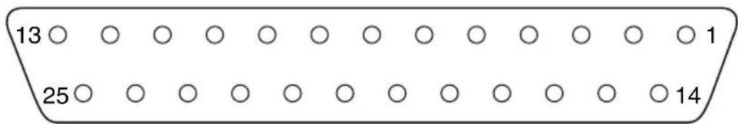
D-1. Serial Interface
Pins and Signal Names
| Pin No. | Signal Name | Direction | Function |
| 1 | F | G | — Frame ground |
| 2 TXD OUT | Transmission data | ||
| 3 RXD IN | Receive data | ||
| 4 RTS OUT | STAR ModeWhen Memory Switch 4-D = 0: Same as DTR signalWhen Memory Switch 4-D = 1: Always SPACEESC/POS ModeSame as DTR signal | ||
| 5 N.C. Not connected | |||
| 6 DSR IN | • DIP Switch 9 = OFFSTAR ModeStatus of this signal is not checked.ESC/POS ModeIn DTR/DSR communication mode when Memory Switch4-5 = 0, indicates whether data receive from host is enabled or disabled.Space: Receive enabledMark: Receive disabledThis signal is not checked in the X-ON/X-OFF communication mode. | ||
| • DIP Switch 9 = ONThis signal used for external reset. Printer is reset whenever signal is in mark state with pulse width of 1mS or more. | |||
| 7 | SG | Signal ground | |
| 8 -19 | N.C. Not connected | ||
| 20 DTR OUT | Indicates | whether data receive from host is enabled or disabled.DTR/DSR Communication ModeSpace when receive is enabled.X-On/X-Off Communication ModeAlways space, except during following conditions:• Period between reset and communication enabled• During self-test printing and dot alignment adjustment | |
| 21 - 24 | N.C. Not connected | ||
| 25 IN | IT IN | • DIP Switch 10 = OFFThis signal not used. | |
| • DIP Switch 10 = ONThis signal becomes reset signal. Printer is reset whenever signal is in space state with pulse width of 1mS or more. | |||
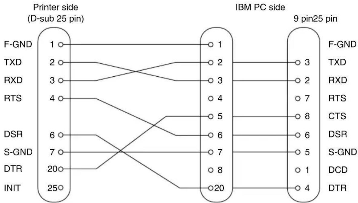
Interface Connections
Refer to the interface specifications of the host for details on connecting to its interface connector. The following illustration shows a typical connection configuration.
flowchart
graph LR
    subgraph Printer side
        F-GND["1"] -->|F-GND| F-GND1["1"]
        TXD["2"] -->|TXD| TXD1["2"]
        RXD["3"] -->|RXD| RXD1["3"]
        RTS["4"] -->|RTS| RTS1["4"]
        DSR["6"] -->|DSR| DSR1["6"]
        S-GND["7"] -->|S-GND| S-GND1["7"]
        DTR["20"] -->|DTR| DTR1["8"]
        INIT["25"] -->|INIT| INIT1["20"]
    end

    subgraph IBM PC side
        F-GND2["3"] -->|F-GND| F-GND2a["1"]
        TXD2["2"] -->|TXD| TXD2a["2"]
        RXD2["7"] -->|RXD| RXD2a["2"]
        RTS2["8"] -->|RTS| RTS2a["7"]
        CTS2["6"] -->|CTS| CTS2a["8"]
        DSR2["5"] -->|DSR| DSR2a["6"]
        S-GND2["1"] -->|S-GND| S-GND2a["5"]
        DCD2["DCD"] -->|DCD| DCD2a["1"]
        DTR2["DTR"] -->|DTR| DTR2a["4"]
    end
D-2. Parallel Interface
The two-way parallel interface is compatible with the IEEE1284 compatibility mode, nibble mode and byte mode. Refer to the separate programmer's manual for details.
Table of connection signals for each mode
| Pin No. | Direction | Compatibility Mode Signal Name | Nibble Mode Signal Name | Byte Mode Signal Name |
| 1 | In nStorobe HostClk | HostClk | ||
| 2 | In/Out Data0 Data0 | Data0 | ||
| 3 | In/Out Data1 Data1 | Data1 | ||
| 4 | In/Out Data2 Data2 | Data2 | ||
| 5 | In/Out Data3 Data3 | Data3 | ||
| 6 | In/Out Data4 Data4 | Data4 | ||
| 7 | In/Out Data5 Data5 | Data5 | ||
| 8 | In/Out Data6 Data6 | Data6 | ||
| 9 | In/Out Data7 Data7 | Data7 | ||
| 10 | Out nAck PtrClk PtrClk | |||
| 11 | Out Busy PtrBusy/ | Data3,7 PtrBusy | ||
| 12 | Out | PError | AckDataReq/Data2,6 | AckDataReq |
| 13 | Out | Select Xflag/Data1,5 | Xflag | |
| 14 | In nAutoFd HostBusy HostBusy | |||
| 15 | N/C | — | — | |
| 16 | GND | GND | GND | |
| 17 | Flame GND Flame GND Flame GND | |||
| 18 | OUT Logic High Logic High Logic High | Logic High | ||
| 19 | GND | GND | GND | |
| 20 | GND | GND | GND | |
| 21 | GND | GND | GND | |
| 22 | GND | GND | GND | |
| 23 | GND | GND | GND | |
| 24 | GND | GND | GND | |
| 25 | GND | GND | GND | |
| 26 | GND | GND | GND | |
| 27 | GND | GND | GND | |
| 28 | GND | GND | GND | |
| 29 | GND | GND | GND | |
| 30 | GND | GND | GND | |
| 31 In nInit nInit nInit | ||||
| 32 Out nFault nDataAvail/Data0,4 nDataAvail | ||||
| 33 EXT GND — | — | |||
| 34 Out Compulsion Status — | — | |||
| 35 Out +5V — | — | |||
| 36 In nSelectIn 1284Active 1284Active | ||||
Note: 1. The prefix “n” on the signal name refers to low active signals. If the host does not have any one of the signal lines listed above, two-way communication fails.
2. For interfacing, signal lines should always use twisted pair cables with the return sides connected to the signal ground level.
3. Cautions when resetting the printer using the nInit signal (#31 pin). Reset can be made from #31 pin (nInit signal) of the interface when the DIP switch 1 is set to on. (Factory setting is on.) In addition, when reset has been enabled by #31 pin (nInit signal), it can be set to reset when the following conditions have been established: DIP switch 2 has been set to off, #36 pin (nSelectIn/1284 active signal) is low, and #31 pin (nInit signal) is low.
4. During factory output, IFEE 1284 printer device ID reply will be “Invalid.” To get the device ID, change DIP switch 6 to “OFF (Valid).”
Function for compatibility mode
| Pin No. | Signal Name IN/OUT Function | ||
| 1 nStorobe IN | Signals when data is ready to be read. Signal goes from HIGH to LOW (for at least 0.5 microsec.) when the data is available. | ||
| 2-9 Data0-7 IN | These signals provide the information of the first to eighth bits of parallel data. Each signal is at HIGH level for a logical 1 and at a LOW level for a logical 0. | ||
| 10 nAck OUT A 9 microsecond LOW pulse acknowledges receipt of the data. | |||
| 11 Busy OUT | When this signal goes to LOW, the printer is ready to accept data. When the printer is in one of the conditions below, “HIGH” is set.1. Data is being entered2. Off line3. Error condition | ||
| 12 PError OUT | This signal indicates the status of the paper sensor.[In Star mode]This signal goes to HIGH when either the TOF or the BOF sensor detects that there is no paper. The signal will go to LOW when both the TOF and BOF sensor detect that there is paper installed.[In the ESC/POS mode]This signal outputs the status of the sensor selected using the“c3” command. | ||
| 13 Select OUT This signal is HIGH when the printer is online. | |||
| 14 nAutoFd IN Unused | |||
| 15 N/C | Unused | ||
| 16 GND | Signal ground | ||
| 17 Flame GND | Chassis ground, isolated from logic ground | ||
| 18 Logic High | 3.9 kΩ pull-up | ||
| 19-30 GND | Twisted pair return the signal to ground level. | ||
| 31 nInit | IN | This becomes a reset signal when DIP switch 1 is set to ON. (See page 128 for details.) When this signal goes to LOW (for at least 0.5 microsec.), the printer is reset to its power-on condition. | |
| 32 nFault OUT | This signal is normally HIGH. This signal goes to LOW to signal that the printer cannot print due to an error condition. | ||
| 33 EXT GND | External ground | ||
| 34 | Compulsion Status | OUT Compulsion signal (See page 138.) | |
| 35 +5 | V 2.2 k | Ω pull-up | |
| 36 n | SelectIn IN | Unused (However, this becomes a reset signal when DIP switch 1 is set to ON and DIP switch 2 is set to OFF. See page 128 for details.) | |
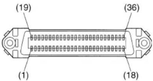
text_image
(19) (36) (1) (18)This connector mates with an Amphenol 57-30360 connector
Parallel interface connector (printer side)
Appendix E: Peripheral Unit Driver Circuit
This printer is equipped with a circuit for driving peripheral units, such as cash drawers. A 6-pin modular connector for connection of the peripheral unit is located on the back of the printer. To connect to the drive circuit, connect the peripheral unit to the modular connector using a cable supplied by you like that one shown in the figure below.
Important!
Never connect any other type of plug to the peripheral unit connector.
Modular plug
Modular plug: MOLEX 90075-0007, AMP641337, or JAPAN BURNDY B-66-4
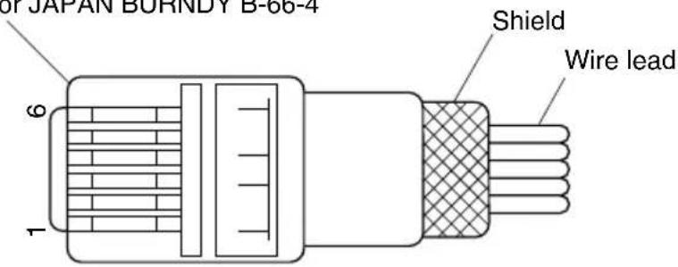
text_image
JAPAN BURND T B-66-4 Shield Wire lead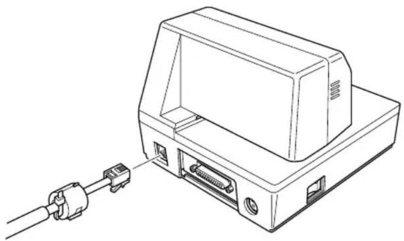
natural_image
Line drawing of a device with an attached cable and connector (no text or symbols)Drive circuit
The recommended drive unit is shown below.
Drive output: 24V, 1.0A max.
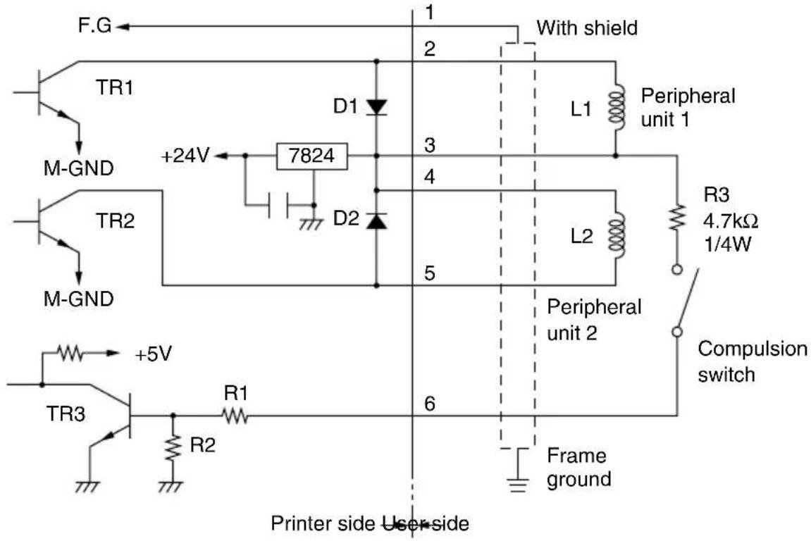
text_image
F.G TR1 M-GND +24V 7824 D1 D2 With shield L1 Peripheral unit 1 3 4 5 L2 Peripheral unit 2 R3 4.7kΩ 1/4W Compulsion switch TR2 M-GND +5V R1 R2 6 Frame ground Printer side User-sideNotes
- Peripheral Units 1 and 2 cannot be driven simultaneously.
- For continuous driving, do not use drive duty greater than 20% .
- The status of the compulsion switch can be known from the following. Star mode: The status of the compulsion switch can be known by using the automatic status function or
ESC/POS mode : The status of the compulsion switch can be known by using the automatic status function,
Parallel interface: The status of the compulsion switch can be known by pin No. 34 on the parallel interface connector. When the compulsion switch is on, pin No. 34 will be low. This can be checked by using the compatibility mode.
• Minimum resistance for coils L1 and L2 is 24 Ω.
- Absolute maximum ratings for diodes D1 and D2 (Ta = 25 °C) are: Average Rectified Current Io = 1A Maximum forward surge current (60Hz, 1-cycle sine wave) I _FSM = 40A
- Absolute maximum rating for transistors TR1 and TR2 (Ta = 25 °C) are: Collector current Ic = 2A Collector loss Pc = 1.2W
WEEE Statement

In the European Union, this label indicates that this product should not be disposed of with household waste. It should be deposited at an appropriate facility to enable recovery and recycling in accordance with legislation under the WEEE Directive (Directive 2002/96/EC).

natural_image
Symbol of a trash bin crossed with a diagonal line, no text or numbers present
SPECIAL PRODUCTS DIVISION STAR MICRONICS CO., LTD.
536 Nanatsushinya, Shimizu-ku, Shizuoka, 424-0066 Japan
Tel: (int+81)-54-347-0112
Fax: (int+81)-54-347-0409
Please access the following URL http://www.star-m.jp/eng/dl/dl02.htm for the latest revision of the manual.
OVERSEAS SUBSIDIARY COMPANIES STAR MICRONICS AMERICA, INC.
1150 King Georges Post Road, Edison, NJ 08837-3729 U.S.A.
Tel: (int+1)-732-623-5555, Fax: (int+1)-732-623-5590
STAR MICRONICS EUROPE LTD.
Star House, Peregrine Business Park, Gomm Road, High Wycombe, Bucks, HP13 7DL, U.K. Tel: (int+44)-1494-471111, Fax: (int+44)-1494-473333
STAR MICRONICS ASIA LTD.
Rm. 1901-5, 19/F., Enterprise Square Two, 3 Sheung Yuet Road, Kowloon Bay, Hong Kong Tel : (int+852)-2796-2727, Fax : (int+852)-2799-9344