SP500 - Printer Star Micronics - Free user manual and instructions
Find the device manual for free SP500 Star Micronics in PDF.

User questions about SP500 Star Micronics
0 question about this device. Answer the ones you know or ask your own.
Ask a new question about this device
Download the instructions for your Printer in PDF format for free! Find your manual SP500 - Star Micronics and take your electronic device back in hand. On this page are published all the documents necessary for the use of your device. SP500 by Star Micronics.
USER MANUAL SP500 Star Micronics
Federal Communications Commission Radio Frequency Interference Statement
This device complies with Part 15 of the FCC Rules. Operation is subject to the following two conditions: (1) This device may not cause harmful interference, and (2) this device must accept any interference received, including interference that may cause undesired operation.
NOTE: This equipment has been tested and found to comply with the limits for a Class A digital device, pursuant to Part 15 of the FCC Rules. These limits are designed to provide reasonable protection against harmful interference when the equipment is operated in a commercial environment. This equipment generates, uses and can radiate radio frequency energy and, if not installed and used in accordance with the instruction manual, may cause harmful interference to radio communications. Operation of this equipment in a residential area is likely to cause harmful interference in which case the user will be required to correct the interference at his own expense.
This statement will be applied only for the equipments marketed in U.S.A.
FCC WARNING
Changes or modifications not expressly approved by the party responsible for compliance could void the user's authority to operate the equipment.
For compliance with the Federal Noise Interference Standard, this equipment requires a shielded cable.
For RF interference suppression, if a ferrite core is provided with this device, affix it to the interface cable.
Statement of The Canadian Department of Communications Radio Interference Regulations
This Class A digital apparatus complies with Canadian ICES-003.
The above statement applies only to printers marketed in Canada.
Trademark acknowledgments
SP500 Series: Star Micronics Co., Ltd.
ESC/POS: Seiko Epson Corporation
Notice
- All rights reserved. Reproduction of any part of this manual in any form whatsoever, without STAR's express permission is forbidden.
The contents of this manual are subject to change without notice. - All efforts have been made to ensure the accuracy of the contents of this manual at the time of going to press. However, should any errors be detected, STAR would greatly appreciate being informed of them.
- The above notwithstanding, STAR can assume no responsibility for any errors in this manual.
TABLE OF CONTENTS
- Outline 1
2.Unpacking and Installation 2
2-1.Unpacking 2
2-2. Locating the Printer 3
2-3. Handling Care 3
2-4. Maintenance 3
- Parts Identification and Nomenclature 4
- Connecting Cables and Power Cord 6
4-1. Connecting the Interface Cable 6
4-2. Connecting to a Peripheral Unit 7
4-3. Connecting the Power Cord 8
4-4. Turning Power On 9
4-5. Attaching the Rear Cover 9
4-6. Installing the Cable 10
4-7. Switch Blind Installation 11
- Loading the Ribbon Cartridge and Paper 12
5-1. Tear Bar Model 12
5-2. Auto Cutter Model 15
5-3. Installing the Roll Paper Guide 18
5-4 Clearing Paper Jams. 19
- Control Panel and Other Functions 20
6-1. Control Panel 20
6-2. Basic Indicators 20
6-3. Errors 21
6-4. Adjustment Mode 23
Appendix A: General Specifications 104
Appendix B: Serial Interface 107
B-1.Pins and Signal Names 107
B-2. Interface Connections 108
Appendix C: Parallel Interface 109
C-1. Table of Connection Signals for Each Mode 109
Appendix D: DIP Switch Setting 111
D-1. Parallel Interface 111
D-2. Serial Interface 112
Appendix E: Memory Switch Settings 114
Appendix F: Peripheral Unit Driver Circuit 115
Appendix G: Adjusting the Dot Alignment Mode 117
Appendix H: Black Mark Sensor Alignment Mode 119
1. Outline
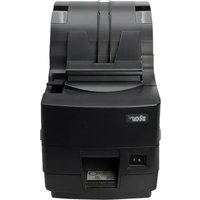
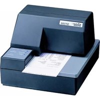
The SP500 Series Serial Impact Dot Matrix Printer is designed for use with electronic instruments such as POS, banking equipment, computer peripheral equipment, etc.
The major features of the SP500 series are as follows:
- Bi-directional printing at approx. 4 lines/sec.
- Serial interface or parallel interface.
- The data buffer allows the unit to receive print data even during printing.
- Peripheral unit drive circuit enables control of external devices such as cash drawers.
2. Unpacking and Installation
2-1. Unpacking
After unpacking the unit, check that all the necessary accessories are included in the package.
Tear bar model Auto cutter model

Ribbon cartridge
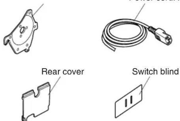
Power cordRoll paper guide
Fig. 2-1 Unpacking
If anything is missing, contact the dealer where you bought the printer and ask them to supply the missing part. Note that it is a good idea to keep the original box and all the packing materials just in case you need to pack the printer up again and send it somewhere at a later date.
2-2. Locating the Printer
When you locate your printer, keep the following tips in mind:
- Protect your printer from excessive heat such as direct sunlight or heaters, and keep it away from moisture and dust.
- Place the printer on a firm, level surface which is fairly vibration-free.
- A steady power supply that is not subject to power surges should be connected to the printer.
For example, do not connect it to the same circuit as a large, noise-producing appliance such as a refrigerator or an air conditioner.
- Make sure the line voltage is the voltage specified on the printer's identification plate.
- To disconnect the printer, the plug has to be disconnected from the wall socket, which has to be located close to the printer, and easy to access.
2-3. Handling Care
- Be careful not to drop paper clips, pins or other foreign matter into the unit as these cause the printer to malfunction.
- Do not attempt to print when either paper or ribbon cartridge is not located in the printer, otherwise the print head can be damaged.
- Do not open the cover while printing.
- Do not touch the print head immediately after printing as it gets very hot.
- Use only roll paper that is not glued to the core.
- When the paper end mark appears on the paper, replace the roll paper before it runs out.
2-4. Maintenance
Essentially, your printer is a robust piece of equipment, but should be treated with a modicum of care in order to avoid malfunctions. For example:
- Keep your printer in a "comfortable" environment. Roughly speaking, if you feel comfortable, then the environment is suitable for your printer.
- Do not subject the printer to physical shocks or excessive vibration.
- Avoid over-dusty environments. Dust is the enemy of all precision mechanical devices.
- To clean the exterior of the printer, use a cloth barely dampened with either water with a little detergent or a little alcohol, but do not allow any liquid to fall inside the printer.
- The interior of the printer may be cleaned with a small cleaner or a compressed-air aerosol (sold for this purpose). When performing this operation, be sure not to bend or damage any cable connections or electronic components.
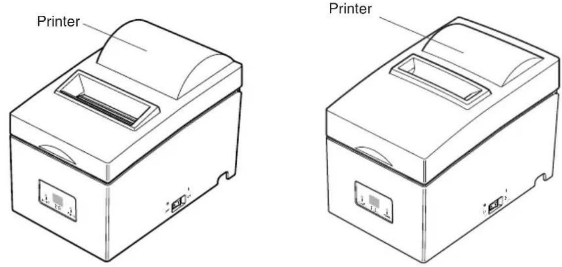
3. Parts Identification and Nomenclature
Tear bar model
Cover
Protects the printer from dust and reduces noise.
Do not open the cover while printing.
Control panel
Features one control switch and two indicators to indicate printer status.
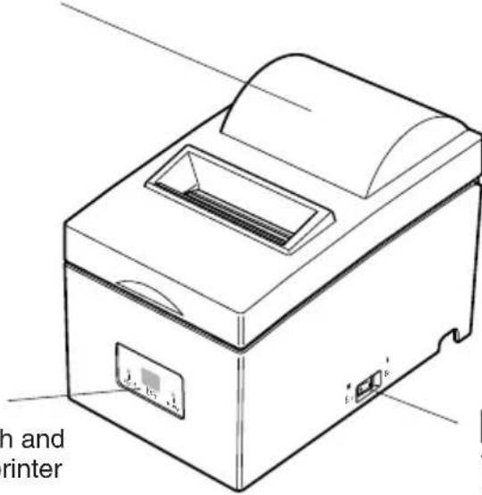
Power switch
Turns printer power on and off.
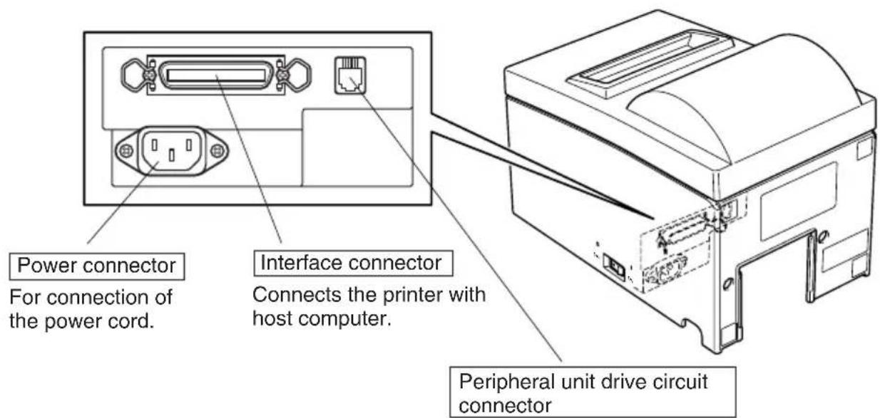
Fig. 3-1 External view of the printer (Tear bar model)
Connects to peripheral units such as cash drawers, etc. Do not connect this to a telephone.
Auto cutter model
Cover
Protects the printer from dust and reduces noise.
Do not open the cover while printing.
Control panel
Features one control switch and two indicators to indicate printer status.
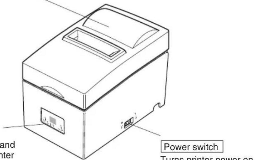
Power switch
Turns printer power on and off.
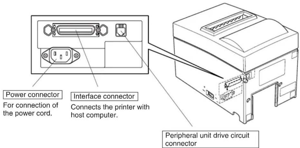
Fig. 3-2 External view of the printer (Auto cutter model)
Peripheral unit drive circuit connector
Connects to peripheral units such as cash drawers, etc. Do not connect this to a telephone.
4. Connecting Cables and Power Cord
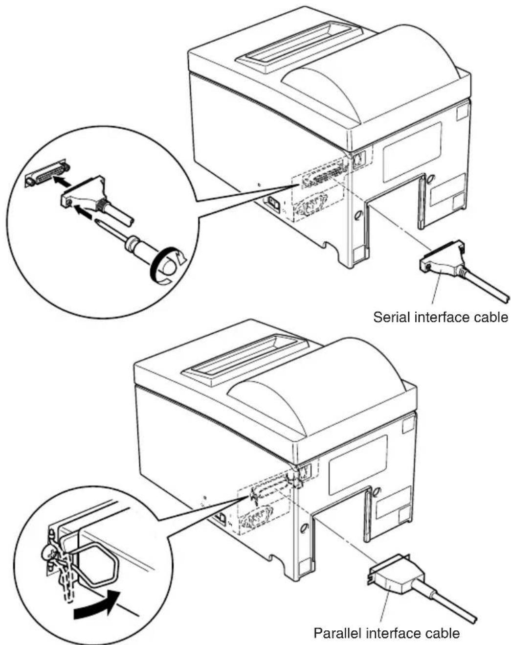
4-1. Connecting the Interface Cable
Note: Before connecting/disconnecting the interface cable, make sure that power to the printer and all the devices connected to the printer is turned off.
Also make sure the power cable plug is disconnected from the AC outlet.
(1)Connect the interface cable to the connector on the rear panel of the printer.
(2) In the case of a serial interface, tighten the connector screws. In the case of a parallel interface, fasten the connector clasps.
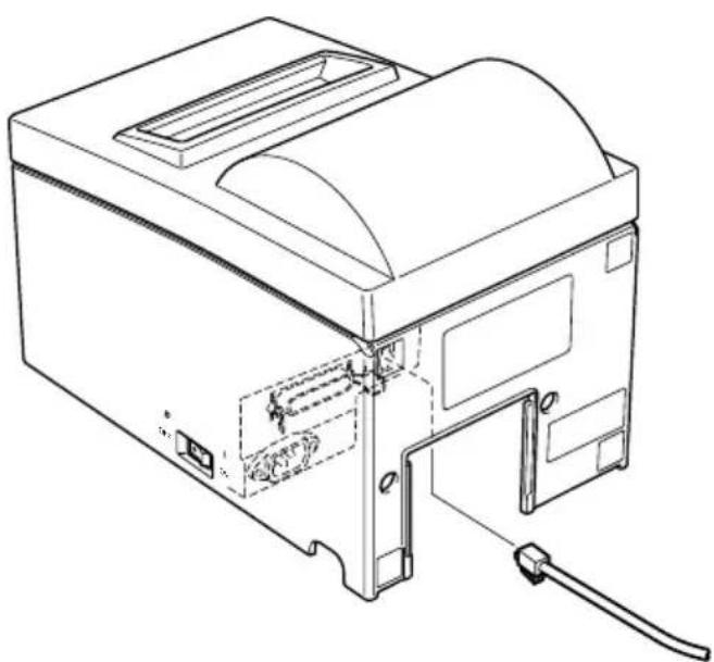
4-2. Connecting to a Peripheral Unit
You can connect a peripheral unit to the printer using a modular plug. The following describes how to install the ferrite core and make the actual connection. See "Modular plug" on page 115 for details about the type of modular plug that is required. Note that this printer does not come with a modular plug or wire, so it is up to you to obtain one that suits your needs.
Important!
Make sure that the printer is turned off and unplugged from the AC outlet and that the computer is turned off before making connections.
(1) Connect the peripheral drive cable to the connector on the rear panel of the printer.
Important!
Do not connect a telephone line into the peripheral drive connector. Failure to observe this may result in damage to the printer.
Also, for safety purposes, do not connect wiring to the external drive connector if there is a chance it may carry peripheral voltage.
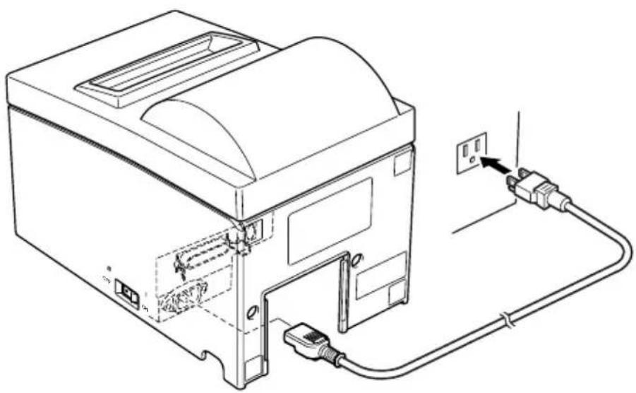
4-3. Connecting the Power Cord
Note: Before connecting/disconnecting the power cord, make sure that power to the printer and all the devices connected to the printer is turned off. Also make sure the power cable plug is disconnected from the AC outlet.
(1) Check the label on the back or bottom of the printer to make sure its voltage matches that of the AC outlet. Also make sure the plug on the power cord matches the AC outlet.
(2) If the power cord is not attached to the printer, plug the appropriate end into the AC inlet on the back of the printer.
(3)Plug the power cord into a properly grounded AC outlet.
Important!
If the voltage shown on the label on the of your printer does not match the voltage for your area, contact your dealer immediately.
4-4. Turning Power On
Make sure that the power cord has been connected as described in 4-3.
(1) Set the power switch located on the right side of the printer to on. The POWER lamp on the control panel will light up.
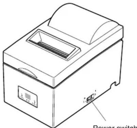
Power switch
Important!
We recommend that you unplug the printer from the power outlet whenever you do not plan to use it for long periods. Because of this, you should locate the printer so that the power outlet it is plugged into is nearby and easy to access.
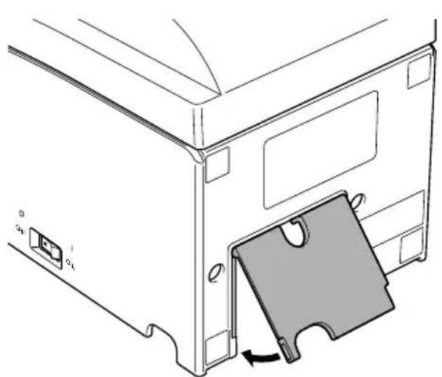
4-5. Attaching the Rear Cover
Attach the rear cover if necessary.

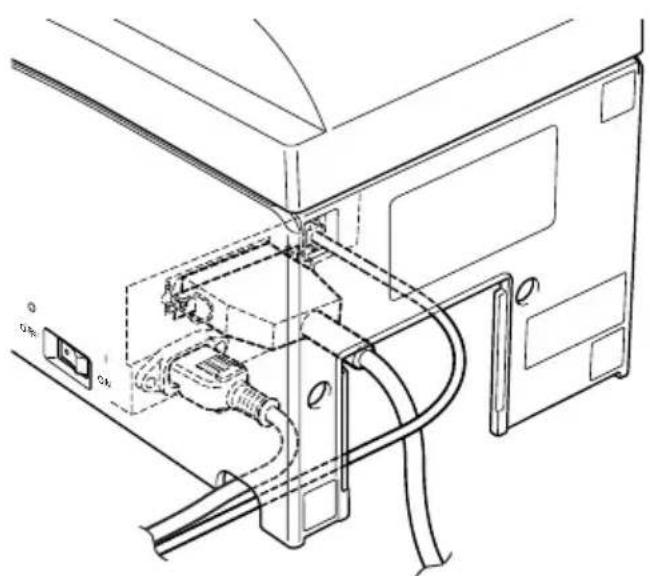
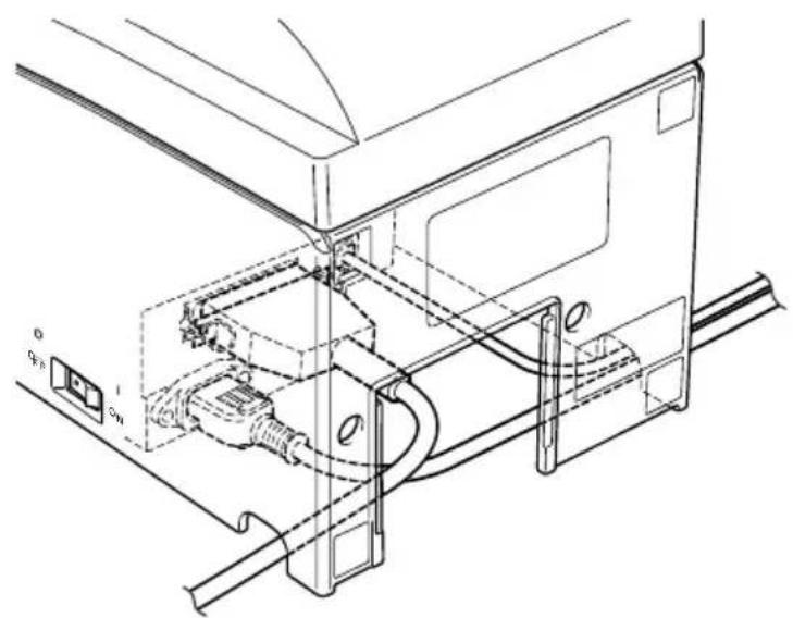
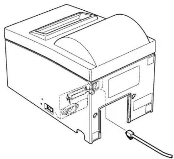
4-6. Installing the Cable
Install the cable as shown in the diagram below.

4-7. Switch Blind Installation
It is not necessary to install the switch blind. Only install it if it is necessary for you. By installing the switch blind, the following become possible.
- Preventing the power switch from being operated by mistake.
- Ensuring that other people can not easily operate the power switch.
Install the switch blind as shown in the diagram below.
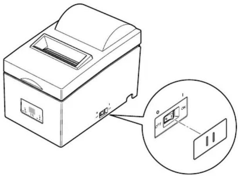
The power switch can be turned ON (I) and OFF (O) by inserting a narrow instrument (ball pen etc) in the holes in the switch blind.
Important!
We recommend that you unplug the printer from the power outlet whenever you do not plan to use it for long periods. Because of this, you should locate the printer so that the power outlet it is plugged into is nearby and easy to access.
5. Loading the Ribbon Cartridge and Paper
5-1. Tear Bar Model
5-1-1. Loading the Ribbon Cartridge
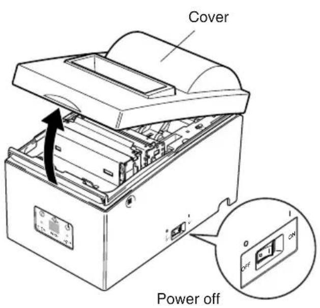
① Turn off power to the printer.
② Open the cover.
Important!
- Do not touch the print head immediately after printing as it can be extremely hot.
- Do not touch the cutter blade.
There is a cutter inside the paper outlet slot. Not only should you not put your hand in the paper outlet slot while printing is in progress, never put your hand into the outlet even when printing is not in progress.
Fig. 5-1 Opening the cover
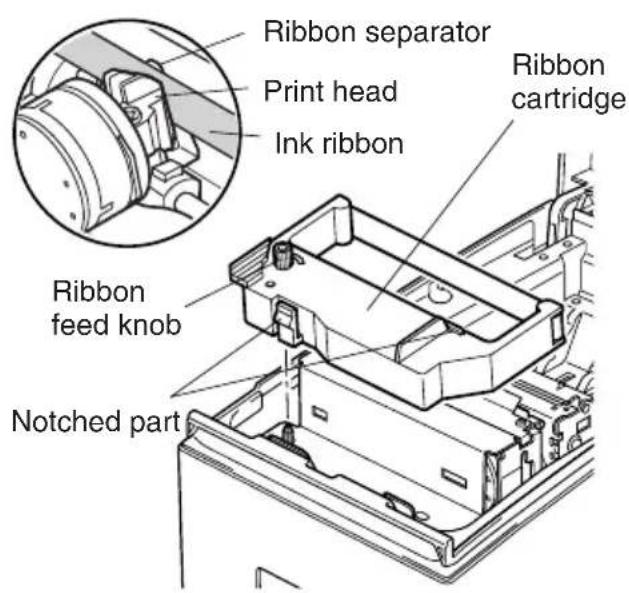
Fig. 5-2 Loading the ribbon cartridge
③ Place the ribbon cartridge in the direction shown in Fig.5-2 and press it down to load it. If loading of the ribbon cartridge is not satisfactory, press down the cartridge while rotating the ribbon feed knob in the direction of the arrow.
④ Turn the ribbon feed knob of the ribbon cartridge in the direction of the arrow to remove slack in the ribbon.
⑤ Close the cover.
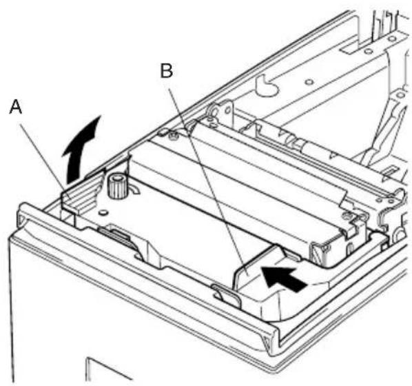
Fig. 5-3 Removing the ribbon cartridge
5-1-2. Loading the paper
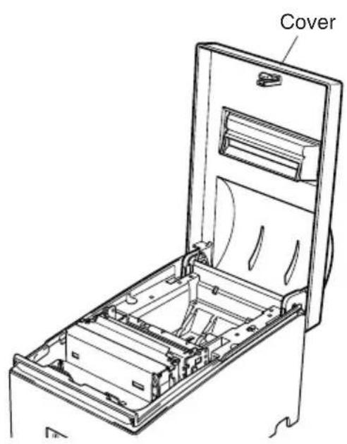
Fig. 5-4 Removing the cover
Note: When removing the ribbon cartridge, raise the A section and then remove it by holding the B section as shown in Fig. 5-3.
① Open the cover.
Important!
- Do not touch the print head immediately after printing as it can be extremely hot.
- Do not touch the cutter blade.
There is a cutter inside the paper outlet slot. Not only should you not put your hand in the paper outlet slot while printing is in progress, never put your hand into the outlet even when printing is not in progress.
② Cut off the front edge of the roll paper perpendicularly.
③ Confirm that the power of the printer is turned on.
④ While observing the direction of the roll, set the paper roll into the hollow as shown in Fig. 5-5.
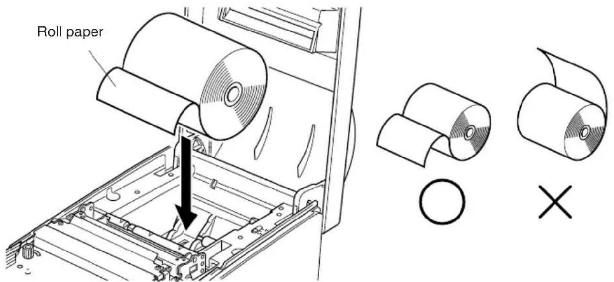
Fig. 5-5 Setting the paper
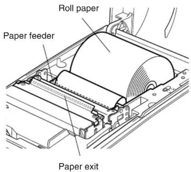
Fig. 5-6 Loading the paper
⑤ Insert the edge of the paper into the paper feeder (black plastic part). If inserted correctly, the edge of the paper will pass through the paper exit.
⑥ Insert the top edge of the paper into the tear bar slot, then mount the cover by reversing the procedure for opening the cover in step ① above.
Note: When the paper end mark appears on the paper, replace the roll paper before it runs out.
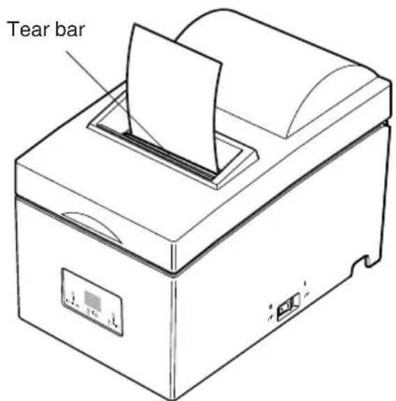
Fig. 5-7
5-2. Auto Cutter Model
5-2-1. Loading the Ribbon Cartridge
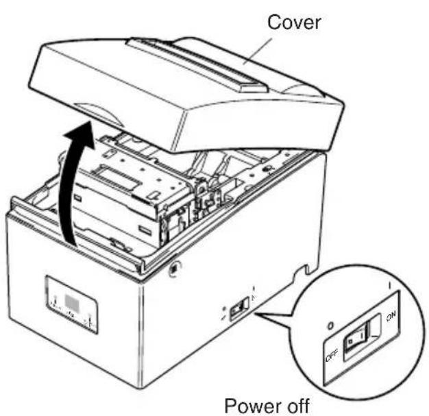
Fig. 5-8 Opening the cover
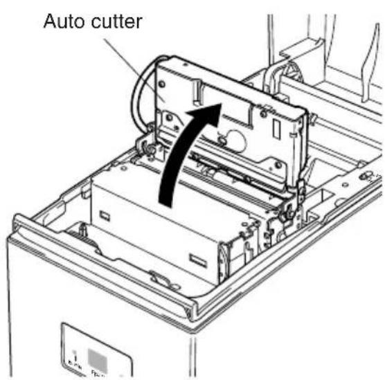
Fig. 5-9 Raise the auto cutter
① Turn off power to the printer.
② Open the cover.
Important!
- Do not touch the print head immediately after printing as it can be extremely hot.
- Do not touch the cutter blade.
There is a cutter inside the paper outlet slot. Not only should you not put your hand in the paper outlet slot while printing is in progress, never put your hand into the outlet even when printing is not in progress.
③ Lift up the auto cutter and put it in a vertical position, as shown in Fig. 5-9.

④ Place the ribbon cartridge in the direction shown in Fig. 5-10 and press it down to load it. If loading of the ribbon cartridge is not satisfactory, press down the cartridge while rotating the ribbon feed knob in the direction of the arrow.
⑤Turn the ribbon feed knob of the ribbon cartridge in the direction of the arrow to remove slack in the ribbon.
⑥Close the Auto Cutter.
⑦Close the cover.
Fig. 5-10 Loading the ribbon cartridge

Fig. 5-11 Removing the ribbon cartridge
Note: When removing the ribbon cartridge, raise the A section and then remove it by holding the B section as shown in Fig. 5-11.
5-2-2. Loading the Paper

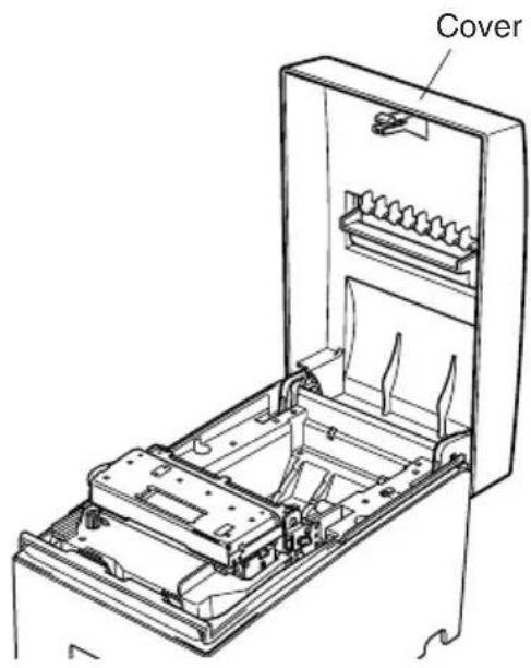
Fig. 5-12 Removing the cover
① Open the cover.
Important!
- Do not touch the print head immediately after printing as it can be extremely hot.
- Do not touch the cutter blade. There is a cutter inside the paper outlet slot. Not only should you not put your hand in the paper outlet slot while printing is in progress, never put your hand into the outlet even when printing is not in progress.
② Cut off the front edge of the roll paper perpendicularly.
③ Confirm that the power of the printer is turned on.
④ While observing the direction of the roll, set the paper roll into the hollow as shown in Fig. 5-13.
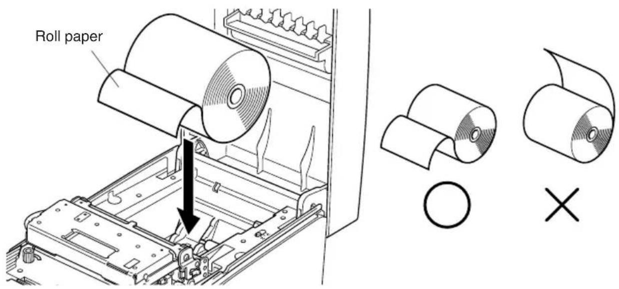
Fig. 5-13 Setting the paper
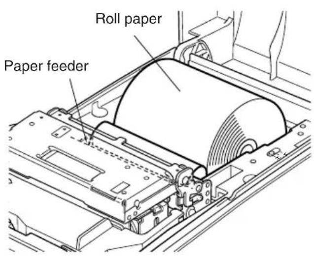
Fig. 5-14 Loading the paper
⑤ Insert the edge of the paper into the paper feeder (black plastic part). If inserted correctly, the edge of the paper will pass through the auto cutter paper slit. Press the FEED button to cut the paper.
⑥ Remove the cut piece of paper and close the cover.
Note: When the paper end mark appears on the paper, replace the paper roll before it runs out.
5-3. Installing the Roll Paper Guide
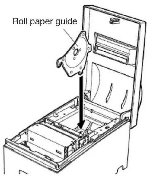
Fig. 5-15 Installing the roll paper guide
When using a paper roll with an 58mm width, install the attached roll paper guide in the groove in the printer.
The setting for memory switch 2-A and 2-B must be changed to change the print width from 63mm to 45mm .
For instructions on setting the memory switch, please refer to the separate Specification Manual.
5-4. Clearing Paper Jams
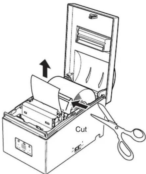
Fig. 5-16 Cutting the paper
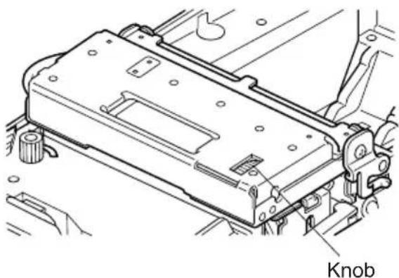
Fig. 5-17 Auto cutter knob
①Turn the printer off and unplug the power cord from the AC outlet.
② Open the cover.
Note: Do not touch the print head immediately after printing, as it can be extremely hot. In addition, do not touch the cutter blade on models equipped with the auto cutter.
For auto cutter models, lift up the auto cutter and put it in a vertical position as shown in Fig. 5-9.
Cut the paper before the paper feeder as shown in Fig. 5-16.
⑤ Remove the jammed paper and reload the roll paper.
Note:
1) When paper is jammed in the autocutter, use a flat-head screwdriver or similar tool to turn the knob and move the cutter blade in order to remove the jammed paper.
2) Do not touch any metal edges. Personal injury could result.
6. Control Panel and Other Functions
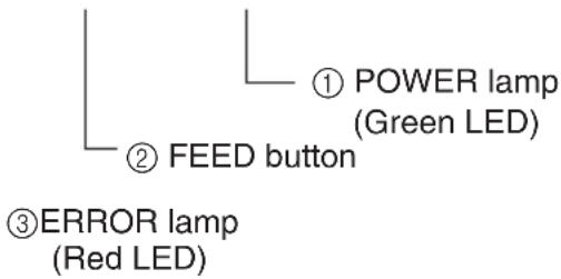
6-1. Control Panel
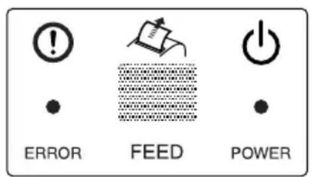
① POWER lamp (Green LED) Lights when the power is ON
② FEED button Press the FEED button to feed roll paper.
③ERROR lamp (Red LED) Indicates various errors in combination with POWER lamp
6-2. Basic Indicators
| POWER lamp | ERROR lamp | Buzzer | |
| Power On/Off | On/Off | — | — |
| No Error | On | Off | — |
6-3. Errors
1) Recoverable error
| Error Description | POWER lamp | ERROR lamp | Buzzer | Recovery Conditions |
| Paper end error | On | On | 4 short beeps (0.13 sec.) repeated twice | *1 |
| Waiting for recovery of the printer to be able to print after loading the roll paper | Flashes (On: 0.25 sec./Off: 0.25 sec.) | Off | None | *2 |
| Paper near end er- ror (Option) | On | Flashes (On: 2 sec./ Off: 2 sec.) | None | *3 |
| Head high tem- perature detection | Flashes (On: 1 sec./Off: 1 sec.) | Off | None | *4 |
| Board high tem- perature detection | Flashes(On:2 sec./ Off: 2 sec.) | Off | None | *5 |
| Cutter error (on models with cutter) | On | Flashes (On: 0.125 sec./Off: 0.125 sec.) | 3 shortbeeps (0.13 sec. + 0.13 sec. + 0.5 sec.) | *6 |
| Mechanicalerror(other than cutter error) | On | Flashes (On: 0.25 sec./Off: 0.25 sec.) | 2 short beeps (0.13 sec. + 0.5 sec.) | *7 |
| Black mark detec- tion error | On | Flashes (On: 0.5 sec./Off: 0.5 sec.) | 3 short beeps (0.13 sec. + 0.13 sec. + 0.13 sec.) | *8 |
*1 After you insert the paper in the paper entrance, the printer loads the paper automatically.
Confirm that the POWER lamp is flashing, and then press the FEED button.
*2 Press the FEED button.
*3 Refer to the separate installation manual of the optional near end sensor for details.
Because the near end sensor is not installed at the time of shipment (factory setting), the error is not displayed if the sensor is not installed.
*4 Automatically the printer is recovered after the print head has cooled.
A print head temperature error is not abnormal.
*5 Automatically the printer is recovered after the board has cooled.
*6 Automatically the printer is recovered if the cutter returns to the home position after turning the power OFF and ON.
Restoration is also possible with the
Note
1) If the cutter doesn't return to the home position, or doesn't perform the initial movement, it cannot be recovered.
2) If the paper is jammed, turn the power OFF, clear the jammed paper, then turn the power ON.
3) When the error occurs:
STAR Mode: Non recoverable error
ESC/POS Mode: Recoverable error
*7 Turn the power OFF, clear the jammed paper or remedy another problem and then turn the power ON. Automatically the printer is recovered if the carriage returns to the home position after turning the power OFF and ON.
Restoration is also possible with the
When the error occurs:
STAR Mode: Non recoverable error
ESC/POS Mode: Recoverable error
*8 For paper jam errors: Clear the jammed paper and change the paper roll if necessary.
For incorrect paper format errors:
Change the paper roll and use a paper roll with the correct black mark.
| Error Description | POWER lamp | ERROR lamp | Buzzer |
| Thermistor failure error | Off | Flashes (On: 0.25 sec./Off: 0.25 sec.) | 2 short beeps (0.13 sec. + 0.5 sec.) |
| Flash memory write error | Off | Flashes (On: 1 sec./Off: 1 sec.) | None |
| RAM R/W error | Off | On | None |
| Power supply error | Off | Flashes (On: 2 sec./Off: 2 sec.) | None |
| CPU error | Off | On | One long beep (2 sec.) |
Note
If a non-recoverable error occurs, turn the power OFF, wait at least 10 seconds, and turn the power back ON. If the non-recoverable error continues to be indicated, consult a dealer for repairs.
6-4. Adjustment Mode
There are the following four adjustment modes.
The device will enter the adjustment mode if your turn it on while pressing the FEED switch.
The Self Printing Mode is entered by releasing the FEED switch after the buzzer sounds once.
(Holding down for 2 more seconds)
Adjusting the Dot Alignment Mode is entered by releasing the FEED switch after the buzzer sounds twice.
(Refer to Appendix G.)
(Holding down for 2 more seconds)
The Hexadecimal Dump Mode is entered by releasing the FEED switch after the buzzer sounds three times.
(Holding down for 2 more seconds)
The Black Mark Sensor Alignment Mode is entered by releasing the FEED switch after the buzzer sounds four times.
(Refer to Appendix H.)

If the buzzer sounds five times or more, immediately turn the power off as the adjustment mode is cancelled.
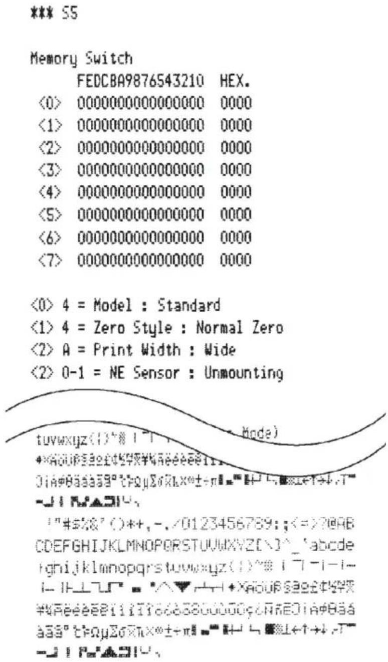
6-4-1. Self Printing Mode
Self-printing will be performed according to the VER. NO., Memory switch settings, DIP switch settings and character order. When the FEED switch is held continuously or when the FEED switch is depressed at the time of the end of self-printing, only the characters will be printed out repeatedly.
6-4-2. Hexadecimal Dump Mode
Each of the signals sent from the computer to the printer will be printed out in hexadecimal code.
This function allows you to check if a control code sent to the printer by the program being used is correct or not. The last line is not printed if its data is less than one full line. However, if the FEED switch is pressed, the last line will be printed. To turn off the mode, it is necessary to turn off the printer completely.
| //// Hexadecimal Dump //// | |||||||||
| 00 | 01 | 02 | 03 | 04 | 05 | 06 | 07 | ...... | |
| 08 | 09 | 0A | 0B | 0C | 0D | OE | OF | ...... | |
| 10 | 11 | 12 | 13 | 14 | 15 | 16 | 17 | ...... | |
| 18 | 19 | 1A | 1B | 1C | 1D | 1E | 1F | ...... | |
| 20 | 21 | 22 | 23 | 24 | 25 | 26 | 27 | !''#$/&' | |
| 28 | 29 | 2A | 2B | 2C | 2D | 2E | 2F | ()*,-./ | |
| 30 | 31 | 32 | 33 | 34 | 35 | 36 | 37 | 01234567 | |
| 38 | 39 | 3A | 3B | 3C | 0A | 89:;<. | |||
TABLE DES MATIERES
- Introduction 27
- Deballage et inspection 28
2-1. Deballage 28
2-2. Emplacement de I'imprimante 29
2-3. Précautions de manipulation 29
2-4. Entretien 29
Appendix A: General Specifications
Printing method: Serial impact dot matrix
Print direction: Bi-directional
Number of head pins: 9 wires
Number of print columns: 42 columns
Character set: ASCII96 (characters)
Extended graphics:
128 × 40 pages (Star mode)
128× 9 pages (ESC/POS)
International characters:
46 (Star mode)
37 (ESC/POS)
Font configuration 7 (Half dots) × 9 or 5× 9
Printing width: 63mm (210 dots)/60 mm (200 dots)/
45mm (150 dots)
Print speed: Approx. 4 lines per sec.
Line spacing: 1/6-inch (default), n/144-inch (programma
ble by command)
Paper feed method: Friction feed
Paper feed speed: Approx. 140~mm / sec
Paper specifications
Paper type: Ordinary bond and carbonless copy paper
Paper width: 76 ± 0.5 ~mm (3.0 inches)/ 57.5 ± 0.5 ~mm (2.25 inches)
Roll diameter: 85mm (3.35 inches) max.
Core: 12 ± 1 ~mm (Inner dia.), 18 ± 1 ~mm (Outer dia.)
Note: Paper rolls with the end of the paper glued or taped to the paper roll core or paper rolls with the end of the paper folded can cause a paper jam. For these paper rolls, use the optional near-end sensor.
Thickness Single: 0.07 mm to 0.10 mm
Copies: Original + 2 copies (Max. 0.2mm )
Paper cutter reliability
Ink ribbon specifications
Ribbon type: Cartridge cassette
Color: Single color (Black)
Ribbon material: Nylon 66 (#40 denier)
Ribbon life: Black 1,500,000 characters
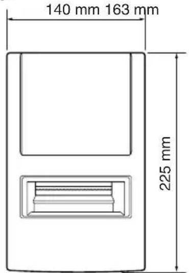
Overall dimensions: 140(W)× 225(D)× 163(H)mm
Weight: Approx. 2.0kg (Tear bar model)
Approx. 2.2kg (Auto cutter model)
Tear Bar Model
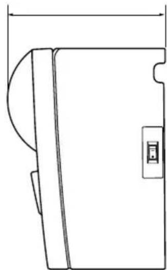
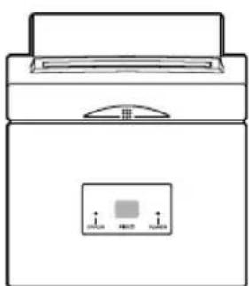
Auto Cutter Model
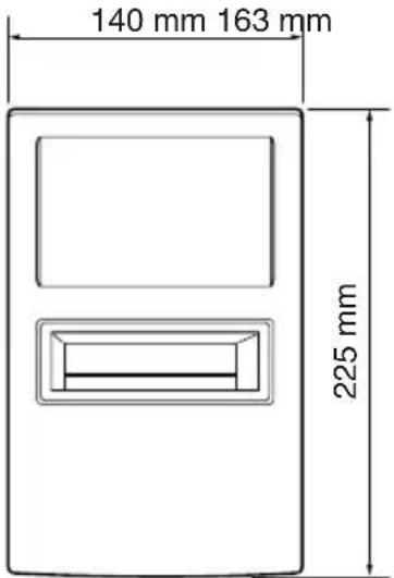
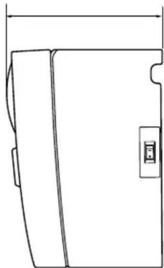
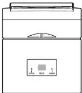
Fig. A-1 Overall dimensions (mm)
Interface
Serial interface: RS-232C
Bidirectional parallel interface: IEEE1284 compatibility and nibble modes Peripheral unit drive circuit: 2 circuits (24V, max. 1A) Ambient temperature/humidity
Operating temperature: 0^ to +40^
Operating humidity: 10% to 90% RH (without condensation)
Storage temperature: -20^ to +70^
Storage humidity: 5% to 95% RH (at 40^ , without condensation)
Mechanical Life: 9 million lines (except head life and auto cutter)
Print head life: 100 million characters
Power Supply Specifications
Power Supply:
Input: 100 to 240V AC, 50/60Hz
Consumption Current:
Conditions: Excluding peripheral unit driving
Operating: Continuous ASCII printing: 0.80 A
Stand-by: 0.12 A
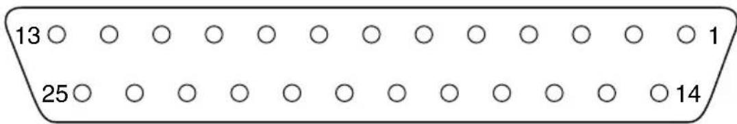
Appendix B: Serial Interface
B-1. Pins and Signal Names
| Pin No. | Signal Name | Direction Function | ||
| 1 | F | G | — Frame ground | |
| 2 TXD | OUT Transmission data | |||
| 3 RXD | IN Receive data | |||
| 4 RTS | OUT Always space | |||
| 5 N.C. | Not connected | |||
| 6 DSR | IN STAR Mode | Status of this signal is not checked.ESC/POS ModeIn DTR/DSR communication mode when Memory Switch4-5=0, indicates whether data receive from host is enabled or disabled. Space:Receive enabledMark:Receive disabledIn DTR/DSR communication mode when Memory Switch 4-5=1, status of this signal is not checked.This signal is not checked in the X-ON/X-OFF communication mode. | ||
| 7 SG Signal ground | ||||
| 8 -19 | N.C. Not connected | |||
| 20 | DTR | OUT | Indicates whether data receive from host is enabled or disabled.DTR/DSR Communication ModeSpace when receive is enabled. | |
| Printer status | Memory switch 6-9 | |||
| 01 | ||||
| 1. During the period from when the power is turned on (including resetting using the interface) to when the printer is ready to receive data. | BUSYBUSY | |||
| 2. During self printing and dot alignment adjustment. | BUSYBUSY | |||
| 3. When the printer stops printing due to a paper end or an optional paper near end. | BUSY— | |||
| 4. When an error has occurred. | BUSY— | |||
| 5. When the receive buffer becomes full. | BUSYBUSY | |||
| Pin No. | Signal Name | Direction Function | |
| 20 DTR OUT X-On/X-Off Communication Mode | |||
| Always space, except during following conditions: • Period between reset and communication enabled • During self printing and dot alignment adjustment | |||
| 21 - 25 N | C. Not connected | ||
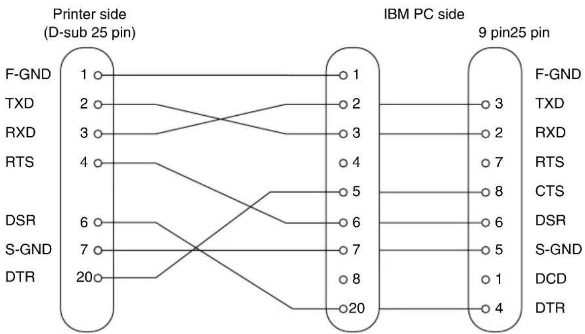
B-2. Interface Connections
Refer to the interface specifications of the host for details on connecting to its interface connector. The following illustration shows a typical connection configuration.
Appendix C: Parallel Interface
The two-way parallel interface is compatible with the IEEE1284 compatibility mode and nibble mode.
C-1. Table of Connection Signals for Each Mode
| Pin No. | Direction | Compatibility Mode Nibble Mode Signal Name Signal Name | |
| 1 In nStrobe Host | _clk | ||
| 2 In Data0 Data0 | |||
| 3 In Data1 Data1 | |||
| 4 In Data2 Data2 | |||
| 5 In Data3 Data3 | |||
| 6 In Data4 Data4 | |||
| 7 In Data5 Data5 | |||
| 8 In Data6 Data6 | |||
| 9 In Data7 Data7 | |||
| 10 Out nAck PtrClk | |||
| 11 Out Busy PtrBusy/Data3,7 | |||
| 12 Out PError | AckDataReq/Data2,6 | ||
| 13 Out Select | Xflag/Data1,5 | ||
| 14 | In | nAutoFd | HostBusy |
| 15 | N/C | - | |
| 16 | GND | GND | |
| 17 | Flame GND | Flame GND | |
| 18 | OUT | Logic High | Logic High |
| 19 | GND | GND | |
| 20 | GND | GND | |
| 21 | GND | GND | |
| 22 | GND | GND | |
| 23 | GND | GND | |
| 24 | GND | GND | |
| 25 | GND | GND | |
| 26 | GND | GND | |
| 27 | GND | GND | |
| 28 | GND | GND | |
| 29 | GND | GND | |
| 30 | GND | GND | |
| 31 In | nInit nInit | ||
| 32 Out | nFault nDataAvail/Data0,4 | ||
| 33 EXT GND — | |||
| 34 Out | Compulsion Status — | ||
| 35 Out | Logic High — | ||
| 36 In | nSelectIn | 1284Active | |
Note: 1. The prefix "n" on the signal name refers to low active signals.
If the host does not have any one of the signal lines listed above, two-way communication fails.
- For interfacing, signal lines should always use twisted pair cables with the return sides connected to the signal ground level.
- Cautions when resetting the printer using the nInit signal (#31 pin). Reset can be made from #31 pin (nInit signal) of the interface by memory switch setting. (Factory setting is reset.)
In addition, when reset has been enabled by #31 pin (nInit signal), it can be set to reset when the following conditions have been established: memory switch settings for 6-D and 6-E have been changed, #36 pin (nSelectIn/1284 active signal) is low, and #31 pin (nInit signal) is low.
For instructions on setting the memory switch, please refer to the separate Specification Manual.
- During factory output, IFEE 1284 printer device ID reply will be "Invalid." To get the device ID, change memory switch 6-C to "Valid." For instructions on setting the memory switch, please refer to the separate Specification Manual.
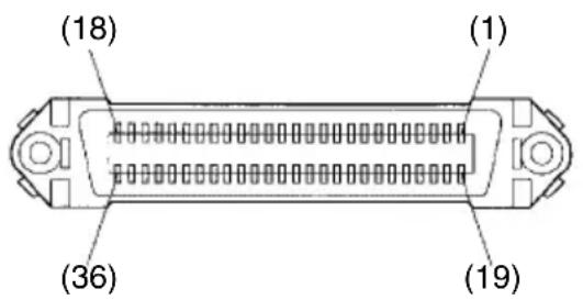
This connector mates with an Amphenol 57-30360 connector
Parallel interface connector (printer side)
Appendix D: DIP Switch Setting
D-1. Parallel Interface
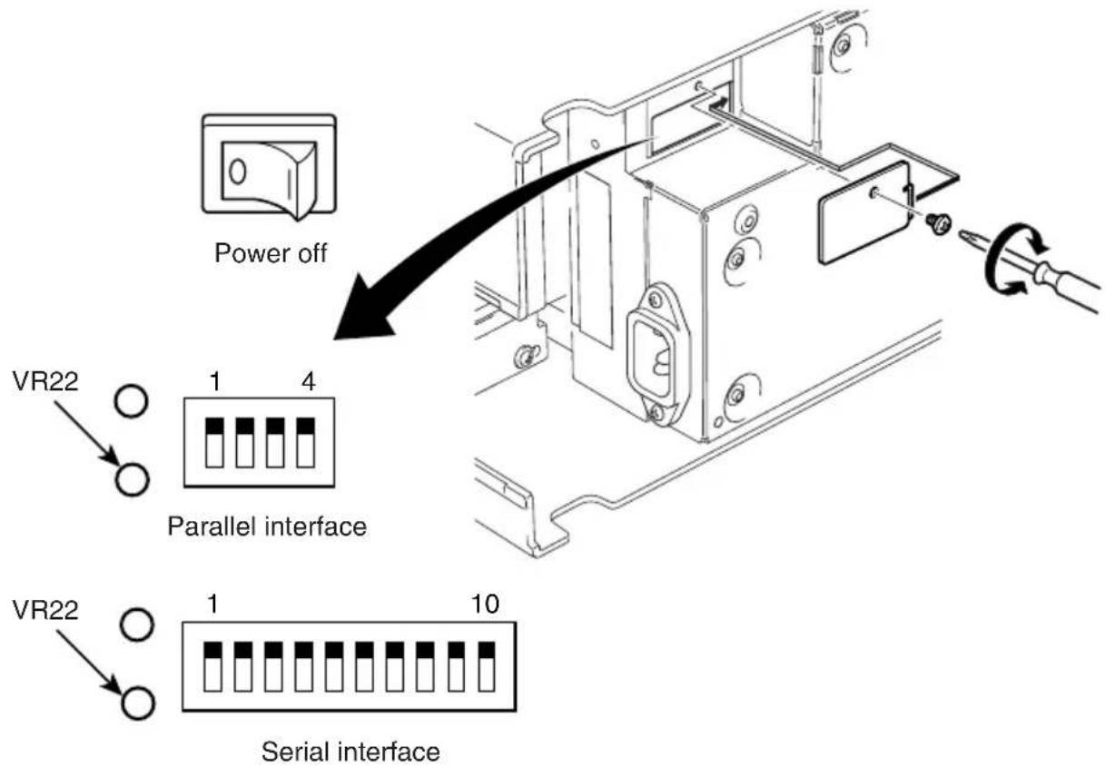
A DIP switch unit is provided at the bottom of the printer, and can be set as given in the table below. Be sure to set the power switch to off before changing the settings. It is recommended to use a pointed item like a pen or flat-blade driver screw to change the settings. The settings will become effective when the power switch is set to on again.
The following is the procedure for changing the settings on DIP switches.
- Turn the printer off and unplug the power cord.
- Remove the screw from the DIP switch cover. Then take off the DIP switch cover, as shown in the illustration below.
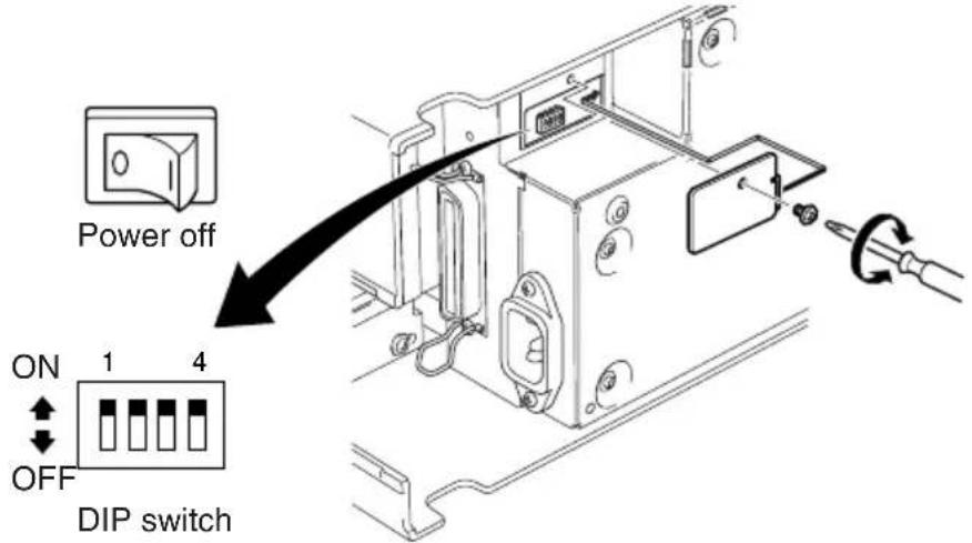
- Set the switches using a pointed tool, such as a pen or flat-blade screwdriver.
- Replace the DIP switch cover. Then secure it with the screw.
The new settings take effect when you turn on the printer.
*1
■DIP switch Factory presetting: All on
| SW No. Function ON OFF | ||
| 1 Always ON Should be set on | ||
| 2 Auto Cutter Invalid Valid | ||
| 3 Always ON Should be set on | ||
| 4 Command emulation Star ESC/POS | ||
*1 The factory settings for enabling/disabling the auto cutter are as follows.
Models without auto cutter: Invalid (Switch 2 = on )
Models with auto cutter: Valid (Switch 2 = off )
Note: Do not enable the auto cutter for models without the auto cutter (i.e., models with a tear bar). A mechanical error will occur.
D-2. Serial Interface
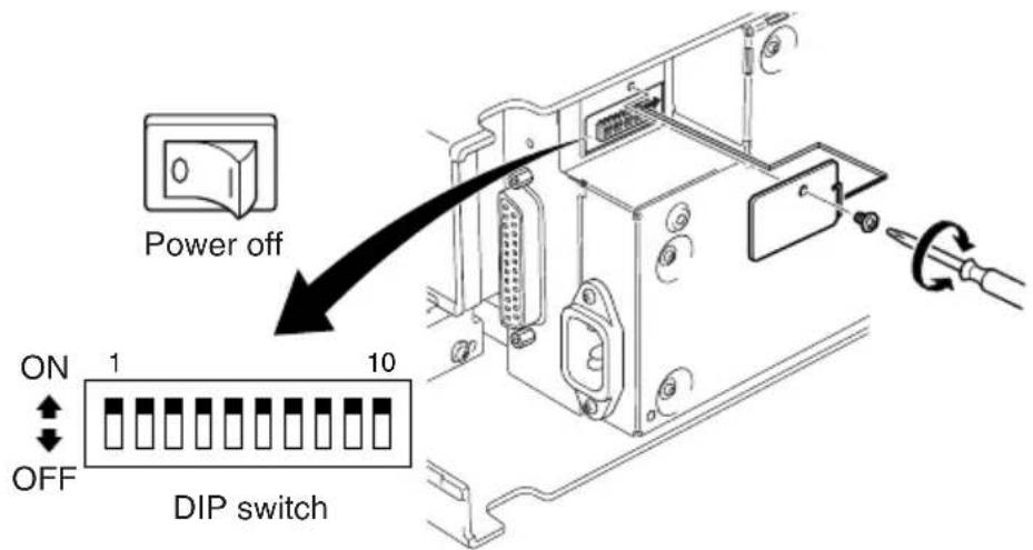
A DIP switch unit is provided at the bottom of the printer, and can be set as given in the table below. Be sure to set the power switch to off before changing the settings. It is recommended to use a pointed item like a pen or flat-blade driver screw to change the settings. The settings will become effective when the power switch is set to on again.
The following is the procedure for changing the settings on DIP switches.
-
Turn the printer off and unplug the power cord.
-
Remove the screw from the DIP switch cover. Then take off the DIP switch cover, as shown in the illustration below.
-
Set the switches using a pointed tool, such as a pen or flat-blade screwdriver.
-
Replace the DIP switch cover. Then secure it with the screw. The new settings take effect when you turn on the printer.
*1
■DIP switch Factory presetting: All ON
| SW No. | Function ON OFF | ||
| 1 | Always ON Should be set on | ||
| 2 | Auto | Cutter Invalid Valid | |
| 3 | Always ON Should be set on | ||
| 4 | Command emulation Star ESC/POS | ||
| 5 | Baud Rate See table below | ||
| 6 | |||
| 7 | Data Length 8 bits 7 bits | ||
| 8 | Parity | Check Disabled Enabled | |
| 9 | Parity | Odd Even | |
| 10 | Handshake | DTR/DSR | XON/XOFF |
*1 The factory settings for enabling/disabling the auto cutter are as follows.
Models without auto cutter: Invalid (Switch 2 = on )
Models with auto cutter: Valid (Switch 2 = off )
Note: Do not enable the auto cutter for models without the auto cutter (i.e., models with a tear bar). A mechanical error will occur.
| Baud Rate | Switch 5 | Switch 6 |
| 4800BPS | OFF | ON |
| 9600BPS | ON | ON |
| 19200BPS | ON | OFF |
| 38400BPS | OFF | OFF |
Appendix E: Memory Switch Settings
Each memory switch is a 16-bit word store in EEPROM. For details on the functions and settings of memory switches, see the separate Specification Manual.
The table below shows the factory settings for the memory switches.
| Memory Switch | Hexadecimal Code |
| 0 0000 | |
| 1 0000 | |
| 2 0000 | |
| 3 0000 | |
| 4 0000 | |
| 5 0000 | |
| 6 0000 | |
| 7 0000 | |
| 8 0000 |
Warning!
Changing the memory switch settings can cause the printer to fail to operate correctly.
Appendix F: Peripheral Unit Driver Circuit
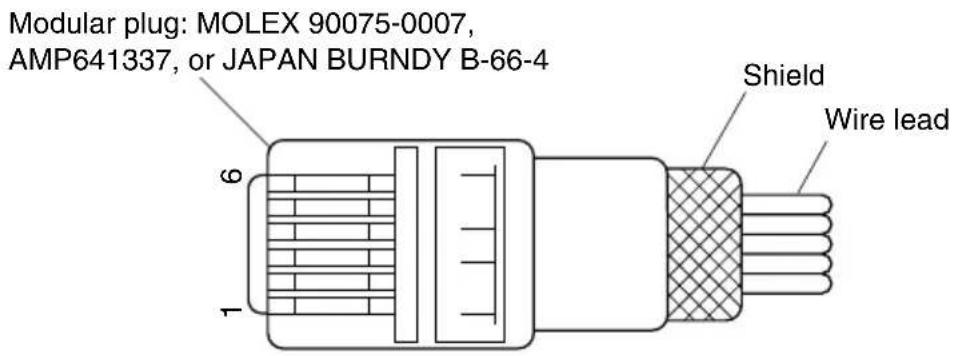
This printer is equipped with a circuit for driving peripheral units, such as cash drawers. A 6-pin modular connector for connection of the peripheral unit is located on the back of the printer. To connect to the drive circuit, connect the peripheral unit to the modular connector using a cable supplied by you like that one shown in the figure below.
Important!
Never connect any other type of plug to the peripheral unit connector.
Modular plug
Drive circuit
The recommended drive unit is shown below.
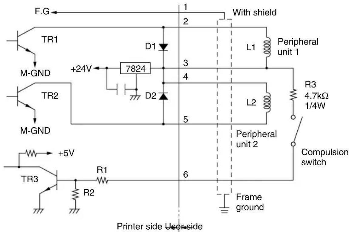
Notes
- Peripheral Units 1 and 2 cannot be driven simultaneously.
- For continuous driving, do not use drive duty greater than 20% .
- The status of the compulsion switch can be known from the following.
Star mode: The status of the compulsion switch can be known by using the automatic status function or
ESC/POS mode: The status of the compulsion switch can be known by using the automatic status function, <DLE> <EOT> n, and <ESC> "u"n commands.
Parallel interface : The status of the compulsion switch can be known by pin No. 34 on the parallel interface connector. When the compulsion switch is on, pin No. 34 will be low. This can be checked by using the compatibility mode.
Minimum resistance for coils L1 and L2 is 24
- Absolute maximum ratings for diodes D1 and D2 (Ta = 25°C) are: Average Rectified Current Io = 1A
- Absolute maximum rating for transistors TR1 and TR2 (Ta = 25°C) are: Collector current Ic = 2A Collector loss Pc = 1.2W
Appendix G: Adjusting the Dot Alignment Mode
You may never have to use the procedure described in this section, but after you have been using your printer for some time you may find that the dots of some graphics do not align correctly. For example, what should look like:

may come out looking like one of the following:

or like this

This is caused when mechanical parts of the printer get out of alignment. This happens only rarely and you may never experience it at all throughout the life of the printer. If you do have problems, use the following procedure to correct it.
- Enter the Dot Alignment Adjust Mode according to the procedure described in Section 6-4.
- After entering the Dot Alignment Adjust Mode, a printout of the adjustment patterns similar to the printout below will be printed. The asterisk indicates the current adjustment pattern.

- To adjust, use the FEED switch to select the adjustment pattern from the printout with the smallest gap between the first printing pass and the return printing pass. Press the FEED switch once to specify the first adjustment pattern, twice to specify the second adjustment pattern, and so on up to seven times to specify the seventh adjustment pattern.
Press and hold the FEED switch the last time you press the switch.
(For example, if you want to select the fourth adjustment pattern, press the FEED switch three times. Then, press and hold the FEED switch until the long buzzer sounds.)
There are only seven adjustment patterns. The buzzer will sound each time the FEED switch is pressed. However, if you press the FEED switch more than seven times, a warning alert will sound.
After selecting the adjustment pattern, the setting value is stored in the non-volatile memory. A printout similar to the one below with the selected adjustment pattern highlighted and the message "Adjust Completed!" will be printed.
Note: Before the printout is printed, the setting value is stored in the non-volatile memory of the printer after the adjustment pattern has been selected and the long buzzer sounds. During this period, do not set the power switch to off. If this power switch is set to off when the setting value is being stored in the non-volatile memory, the setting value for the adjustment pattern and all of the memory switch settings will be reset.

Fig. 6-3 Dot Alignment Adjustment Sample 2
- The long buzzer sounds once more and the setting value is automatically set.
The adjusting the dot alignment mode is complete.
Appendix H: Black Mark Sensor Alignment Mode
-
Turn the printer off and unplug the power cord.
-
Remove the screws. Then, remove the DIP switch cover on the bottom of the printer.
- Since it is adjusted by rotating the volume VR22, check the position of the volume. Prepare a small slotted screwdriver that will fit in the hole.
- Set the roll paper not for black mark.
- Enter the black mark sensor adjustment mode according to the procedure described Section 6-4.
- Rotate the volume VR22 using micro screwdriver, to adjust it to a position where at both the ERROR (red LED) and the POWER (green LED) lamps light.
- Turn the power OFF.
This completes the black mark sensor adjustment.
WEEE Statement

In the European Union, this label indicates that this product should not be disposed of with household waste. It should be deposited at an appropriate facility to enable recovery and recycling in accordance with legislation under the WEEE Directive (Directive 2002/96/EC).

Please access the following URL
http://www star-m.jp/eng/dl/dl02.htm
for the latest revision of the manual.
OVERSEAS SUBSIDIARY COMPANIES
STAR MICRONICS AMERICA, INC.
1150 King Georges Post Road, Edison, NJ 08837-3729 U.S.A.
Tel: (int+1)-732-623-5555, Fax: (int+1)-732-623-5590
STAR MICRONICS EUROPE LTD.
Star House, Peregrine Business Park, Gomm Road, High Wycombe, Bucks, HP13 7DL, U.K.
Tel: (int+44)-1494-471111, Fax: (int+44)-1494-473333
STAR MICRONICS ASIA LTD.
Rm. 1901-5, 19/F., Enterprise Square Two,
3 Sheung Yuet Road, Kowloon Bay, Hong Kong
Tel : (int+852)-2796-2727, Fax : (int+852)-2799-9344