
TSP1043U - Printer Star Micronics - Free user manual and instructions
Find the device manual for free TSP1043U Star Micronics in PDF.

| Product Type | Thermal Printer |
| Brand | Star Micronics |
| Model | TSP1043U |
| Print Technology | Direct Thermal |
| Compatible Paper Width | 44.5 to 82.5 mm |
| Compatible Paper Thickness | 65 to 150 µm |
| Max Roll Outer Diameter | 180 mm (drop-in), 170 mm (with spindle) |
| Power Supply | PS60 power adapter (optional), input AC 100-240V, output DC 24V, 2.0A |
| Available Interfaces | RS-232C, Parallel, USB, Ethernet (depending on model) |
| Functions | Thermal printing, auto cutter, paper feed, self-test, hex dump |
| Control Panel | FEED button, POWER (green) LED, ERROR (red) LED, FEED LED |
| Error Detection | Head temperature, cover open, paper jam, memory errors |
| Paper Loading | Drop-in or with roll spindle |
| Paper Guide | Adjustable paper guides and upper guides |
| Paper End Sensor | Adjustable at 3 levels |
| Maintenance and Cleaning | Print head with isopropyl alcohol; paper support with soft cloth |
| Safety | Caution: hot head after printing, sharp cutter blade |
| Supplied Accessories | Installation sheet, paper stopper, switch cover, ferrite core, fastener, user manual, roll supports (x2), roll spindle (depending on model) |
| Recommended Paper | T8037, TF8067, TF8075, KLS46, KPO460, Lotto482 |
Frequently Asked Questions - TSP1043U Star Micronics
User questions about TSP1043U Star Micronics
0 question about this device. Answer the ones you know or ask your own.
Ask a new question about this device
Download the instructions for your Printer in PDF format for free! Find your manual TSP1043U - Star Micronics and take your electronic device back in hand. On this page are published all the documents necessary for the use of your device. TSP1043U by Star Micronics.
USER MANUAL TSP1043U Star Micronics
Federal Communications Commission Radio Frequency Interference Statement
This device complies with Part 15 of the FCC Rules. Operation is subject to the following two conditions: (1) This device may not cause harmful interference, and (2) this device must accept any interference received, including interference that may cause undesired operation.
NOTE: This equipment has been tested and found to comply with the limits for a Class A digital device, pursuant to Part 15 of the FCC Rules. These limits are designed to provide reasonable protection against harmful interference when the equipment is operated in a commercial environment. This equipment generates, uses and can radiate radio frequency energy and, if not installed and used in accordance with the instruction manual, may cause harmful interference to radio communications. Operation of this equipment in a residential area is likely to cause harmful interference in which case the user will be required to correct the interference at his own expense.
This statement will be applied only for the equipments marketed in U.S.A.
FCC WARNING
Changes or modifications not expressly approved by the party responsible for compliance could void the user's authority to operate the equipment.
For compliance with the Federal Noise Interference Standard, this equipment requires a shielded cable.
For RF interference suppression, if a ferrite core is provided with this device, affix it to the interface cable.
Statement of The Canadian Department of Communications Radio Interference Regulations
This Class A digital apparatus complies with Canadian ICES-003.
The above statement applies only to printers marketed in Canada.
Trademark acknowledgments
TSP1000: Star Micronics Co., Ltd.
ESC/POS: Seiko Epson Corporation
Notice
- All rights reserved. Reproduction of any part of this manual in any form whatsoever, without STAR's express permission is forbidden.
- The contents of this manual are subject to change without notice.
- All efforts have been made to ensure the accuracy of the contents of this manual at the time of going to press. However, should any errors be detected, STAR would greatly appreciate being informed of them.
- The above notwithstanding, STAR can assume no responsibility for any errors in this manual.
TABLE OF CONTENTS
1. Unpacking and Installation .... 1
1-1. Unpacking 1
2. Parts Identification and Nomenclature 2
3. Consumable Parts and AC Adapter 4
4. Connecting Cables and AC Adapter 6
4-1. Interface Cable 6
4-2. Connecting to a Buzzer Drive 10
4-3. Connecting the Optional AC Adapter 11
4-4. Turning Power On 12
4-5. Installing the Cable 13
4-6. Switch Blind Installation 14
5. Control Panel and Other Functions 15
5-1. Control Panel 15
5-2. Errors 15
5-3. Self Printing 17
6. Loading the Roll Paper 18
6-1. Loading the Roll Paper 18
6-2. Paper Loading Methods 21
6-3. Roll Paper Holder Adjustment 22
6-4. Paper Guide Adjustment 23
6-5. Upper Guide Adjustment 24
7. Adjusting the Near-end Sensor 25
8. Preventing and Clearing Paper Jams 27
8-1. Preventing Paper Jams 27
8-2. Removing Paper Jam 27
8-3. Releasing a Locked Cutter 28
9. Periodical Cleaning 30
9-1. Cleaning the Thermal Head 30
9-2. Cleaning the Paper Holder 30
Appendix A: Specifications 128
A-1. General Specifications 128
A-2. Auto Cutter Specifications 129
A-3. Interface 129
A-4. Electrical Characteristics 129
A-5. Option 129
A-6. Environmental Requirements 130
A-7. Reliability 130
A-8. Black Mark Specifications 131
Appendix B: Dip Switch Setting.... 134
B-1. Parallel Interface Model 135
B-2. Sperial Interface (RS-232C) Model 136
B-3. USB Interface Model 138
B-4. Ethernet Interface Model 139
B-5. Wireless LAN Interface Model 141
Appendix C: Parallel Interface 144
Appendix D: Serial Interface (RS-232C) 145
D-1. RSConnector 145
D-2. Cable Connections 147
D-3. Electrical Characteristics 147
Appendix E: USB, Ethernet and Wireless LAN Interface 148
E-1. USB Interface Specifications 148
E-2. Ethernet Interface Specifications 148
E-3. Wireless LAN Interface Specifications 148
Appendix F: Buzzer Driver Circuit 149
Appendix G: Memory Switch Settings 151
1. Unpacking and Installation
1-1. Unpacking
After unpacking the unit, check that all the necessary accessories are included in the package.
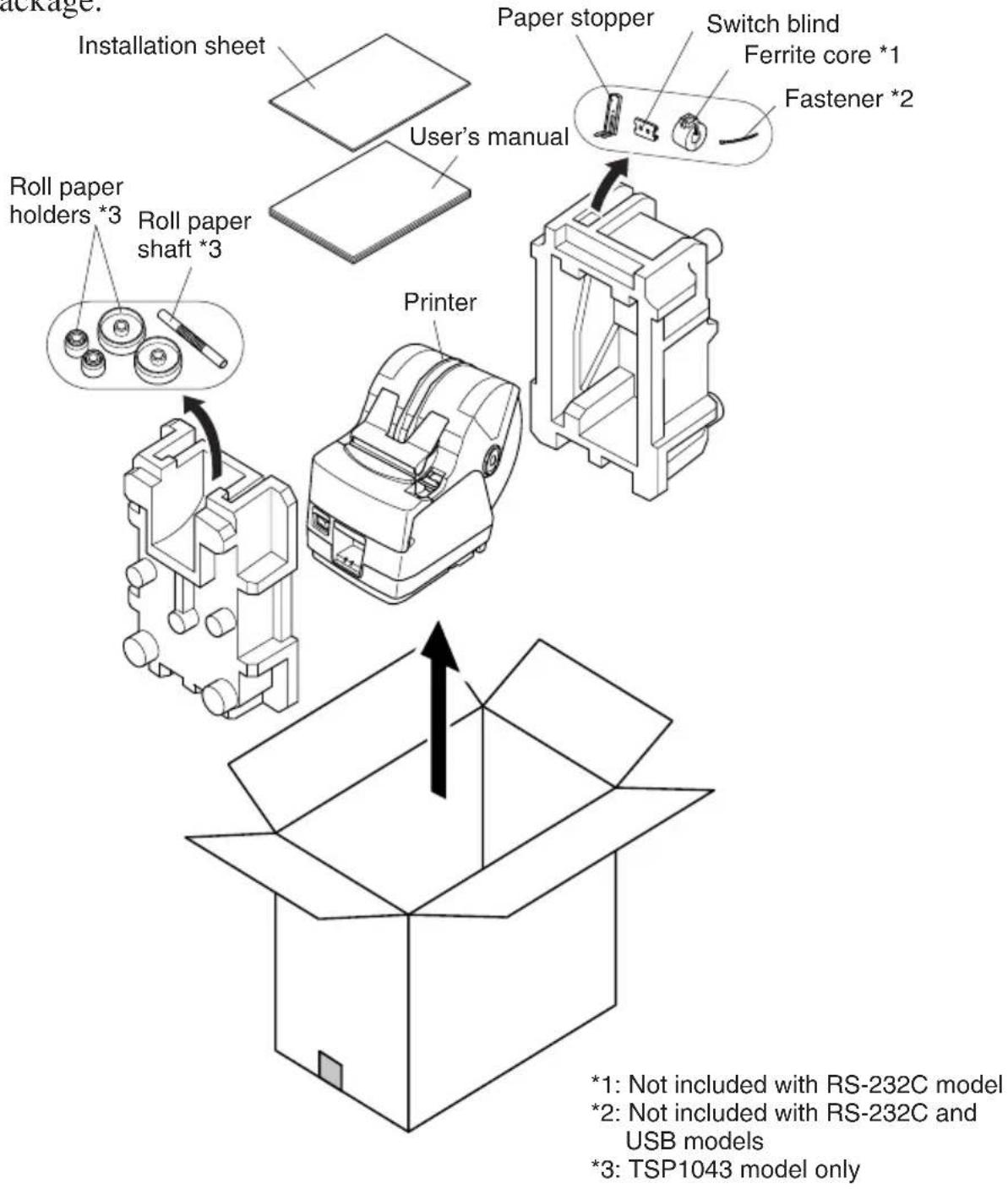
Fig. 1-1 Unpacking
If anything is missing, contact the dealer where you bought the printer and ask them to supply the missing part. Note that it is a good idea to keep the original box and all the packing materials just in case you need to pack the printer up again and send it somewhere at a later date.
2. Parts Identification and Nomenclature
Choosing a place for the printer
Before actually unpacking the printer, you should take a few minutes to think about where you plan to use it. Remember the following points when doing this.
√ Choose a firm, level surface where the printer will not be exposed to vibration.
√The power outlet you plan to connect to for power should be nearby and unobstructed.
√ Make sure that the printer is close enough to your host computer for you to connect the two.
√ Make sure that the printer is not exposed to direct sunlight.
√ Make sure that the printer is well away from heaters and other sources of extreme heat.
√ Make sure that the surrounding area is clean, dry, and free of dust.
√Make sure that the printer is connected to a reliable power outlet. It should not be on the same electric circuit as copiers, refrigerators, or other appliances that cause power spikes.
√Make sure that the room where you are using the printer is not too humid.
WARNING
√Shut down your equipment immediately if it produces smoke, a strange odor, or unusual noise. Immediately unplug the equipment and contact your dealer for advice.
√Never attempt to repair this product yourself. Improper repair work can be dangerous.
√Never disassemble or modify this product. Tampering with this product may result in injury, fire, or electric shock.
3. Consumable Parts and AC Adapter
When consumable parts have run out, use those specified in the table below. Make sure that the AC adapter specified in the table is used.
Use of consumable parts or an AC adapter which are not specified in the table may result in damage to the printer, fire or electric shock.
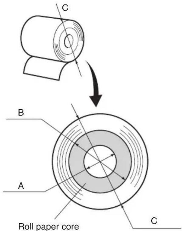
(1) Roll paper specifications
Thermal paper
Thickness: 65 to 150 μm
Width: 44.5 ± 0.5 to 82.5 ± 0.5 mm
Outer roll diameter: Max. ∅180 mm
(When using drop-in paper loading)
Max. ∅170 mm
(When using roll paper shaft)
Take up paper roll width:45 ^+0.5-1 to 83 ^+0.5-1 mm
Core outer/inner diameter
| Paper thickness Core | outer Core inner | |
| 65 – 100 μm | Max. φ40±1 mm | Max. φ25.4±1 mm |
| 100 – 150μm | Max. φ58±1 mm | Max. φ50.8±1 mm |
Printed surface: Outer surface of roll
Tail end handling: Do not use paste or glue to secure the roll paper or its core.
Do not fold the tail end of the paper.
(2) Recommended paper
Mitsubishi Paper Mills Limited
T8037 (tickets), 85 μm (thickness)
TF8067 (tickets), 84 μm (thickness)
TF8075 (tickets), 85 μm (thickness)
KANZAN
KLS46 (tickets)
KPO460 (tickets)
Kanzaki Specialty Papers Inc. (KSP)
Lotto482 (tickets), 84 m (thickness)
Depending on the type and thickness of the paper, it may be necessary to change the settings for printing darkness. To change the darkness settings, use the printing darkness settings command
(3) AC adapter (option)
Model name: PS60
Input: 100 to 240 V AC, 50/60 Hz
Output: DC24±5%, 2.0 A (5.0 A Load 10 sec. Max.)
CAUTION
Access the following URL for the information of the recommended paper.
http://www.star-m.jp/eng/dl/dl02.htm
4. Connecting Cables and AC Adapter
4-1. Interface Cable
Note that the interface cable is not provided. Please use a cable that meets specifications.

CAUTION
Before connecting/disconnecting the interface cable, make sure that power to the printer and all the devices connected to the printer is turned off. Also make sure the power cable plug is disconnected from the AC outlet.
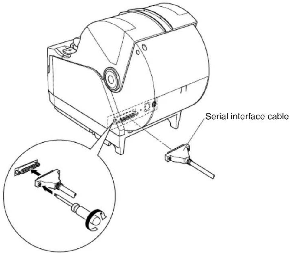
4-1-1. Serial Interface (RS-232C) Cable
(1) Make sure the printer is turn off.
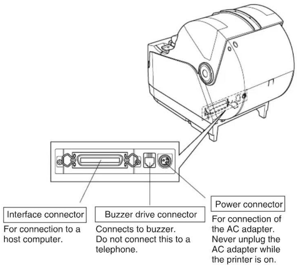
(2)Connect the interface cable to the connector on the rear panel of the printer.
(3) Tighten the connector screws.
4-1-2. Parallel Interface Cable
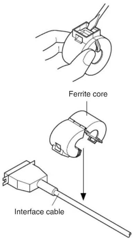
(1) Make sure the printer is turn off.
(2) For only the parallel interface model, affix the ferrite core onto the cable as shown in the illustration below.
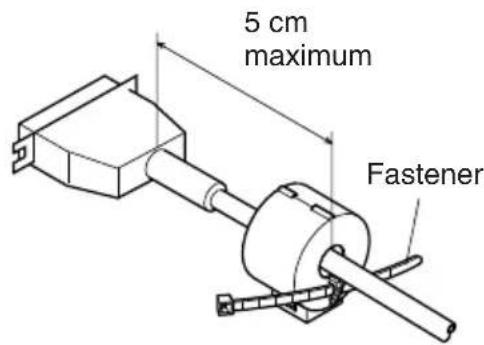
(3) Pass the fastener through the ferrite core.
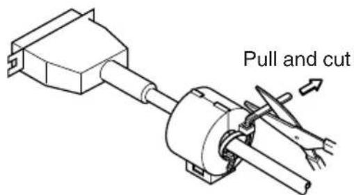
(4)Loop the fastener around the cable and lock it. Use scissors to cut off any excess.
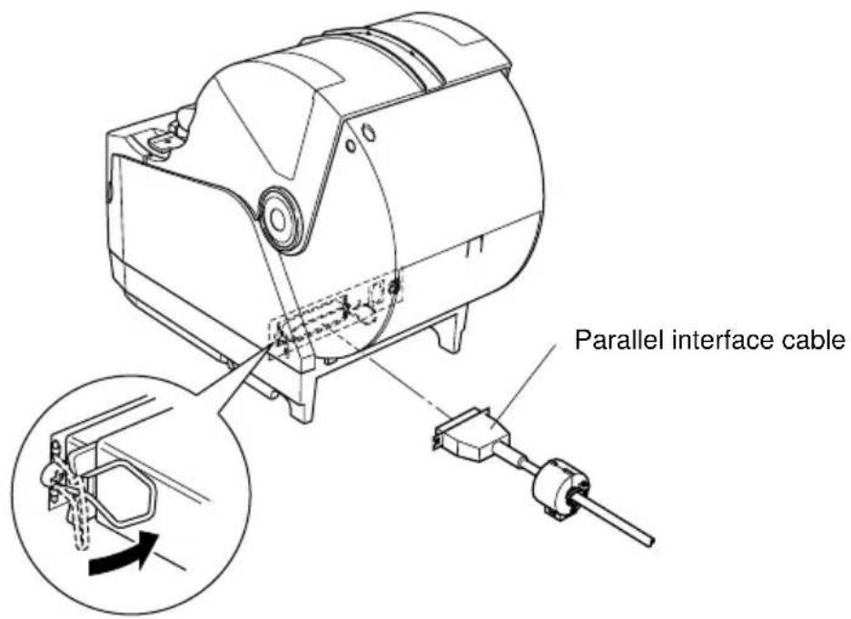
(5)Connect the interface cable to the connector on the rear panel of the printer.
(6)Fasten the connector clasps.
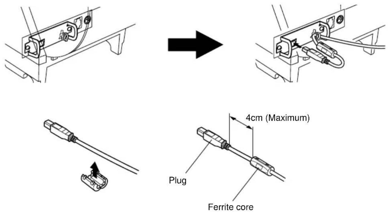
4-1-3. Connecting USB Cable
(1) Make sure the printer is turn off.
(2) Affix the ferrite core onto the USB cable as shown in the illustration below and make sure to pass the cable through the cable support as shown in the illustration.
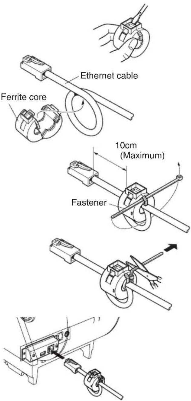
4-1-4. Connecting Ethernet Cable
(1) Make sure the printer is turned off.
(2)Affix the ferrite core onto the ethernet cable as shown in the illustration below.
(3) Pass the fastener through the ferrite core.
(4)Loop the fastener around the cable and lock it. Use scissors to cut off any excess.
(5)Connect the ethernet cable to the connector on the interface board. Then, connect the other end of the cable to your computer.
4-2. Connecting to a Buzzer Drive
You can connect a buzzer drive to the printer using a modular plug. The following describes how to make the actual connection. See “Modular plug” on page 149 for details about the type of modular plug that is required. Note that this printer does not come with a modular plug or wire, so it is up to you to obtain one that suits your needs.
CAUTION
Make sure that the printer is turned off and unplugged from the AC outlet and that the computer is turned off before making connections.
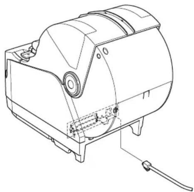
Connect the buzzer drive cable to the connector on the rear panel of the printer.
CAUTION
Do not connect a telephone line into the buzzer drive connector. Failure to observe this may result in damage to the printer.
Also, for safety, do not connect wiring to the buzzer drive connector if there is a chance it may carry excess voltage.
natural_image
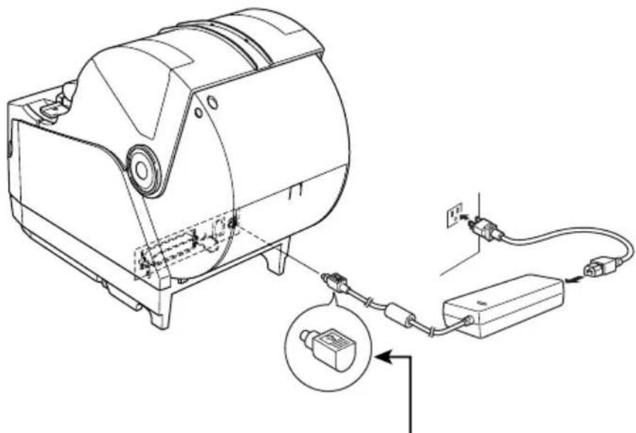
Technical line drawing of a mechanical device with internal components and mounting base (no text or symbols)4-3. Connecting the Optional AC Adapter
Note: Before connecting/disconnecting the AC adapter, make sure that power to the printer and all the devices connected to the printer is turned off. Also make sure the power cable plug is disconnected from the AC outlet.
(1)Connect the AC adapter to the power cable.
Note: Use only the standard AC adapter and power cable.
(2)Connect AC adapter to the connector on the printer.
(3)Insert the power cable plug into an AC outlet.
natural_image
Technical line drawing of a mechanical device connected to a power strip and cable, with an inset showing a close-up of the component (no text or symbols present)CAUTION
When disconnecting the cable, take hold of the cable connector to pull it out. Releasing the lock makes it easy to disconnect the connector.
Pulling the cable excessively could cause damage to the connector.
4-4. Turning Power On
Make sure that the AC adapter has been connected as described in 4-3.
(1) Set the power switch located on the front of the printer to on. The POWER lamp on the control panel will light up.
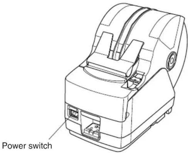
CAUTION
We recommend that you unplug the printer from the power outlet whenever you do not plan to use it for long periods. Because of this, you should locate the printer so that the power outlet it is plugged into is nearby and easy to access.
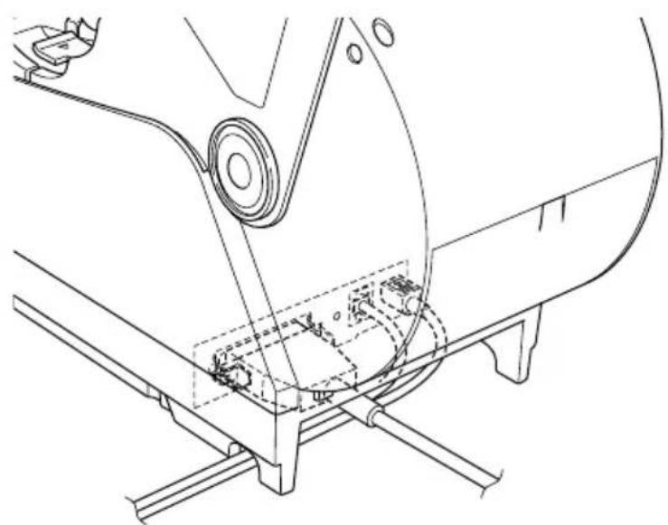
4-5. Installing the Cable
Install the cable as shown in the diagram below.
natural_image
Technical line drawing of a mechanical assembly with no visible text or symbols
natural_image
Technical line drawing of a mechanical assembly with no visible text or symbols
natural_image
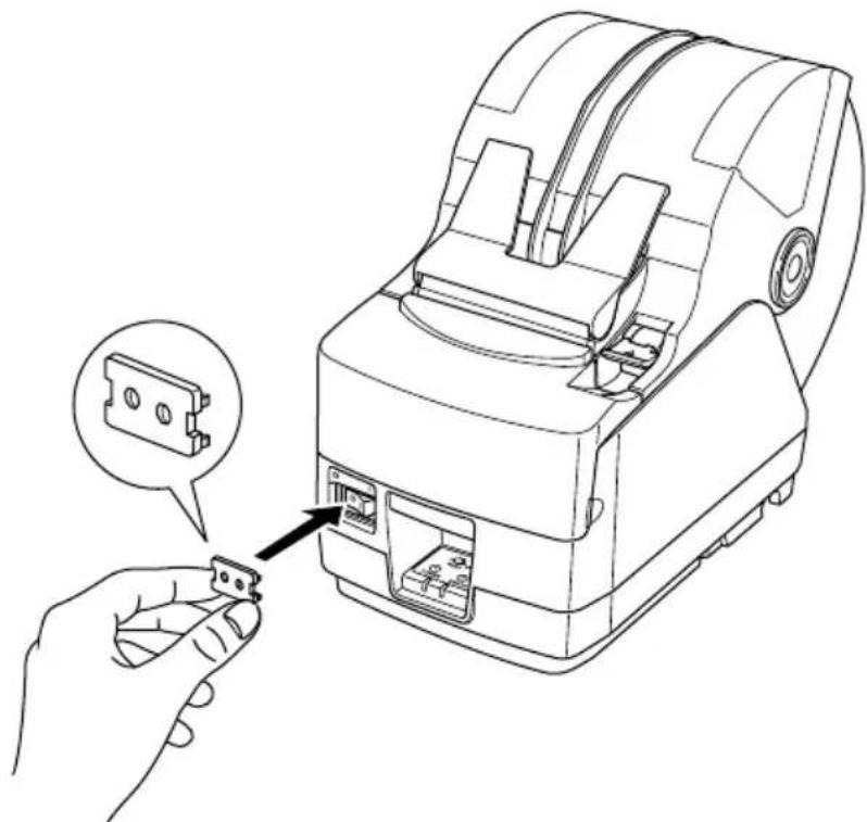
Technical line drawing of a mechanical assembly with mounting brackets and a central circular component (no text or symbols)4-6. Switch Blind Installation
It is not necessary to install the switch blind. Only install it if it is necessary for you. By installing the switch blind, the following become possible.
- Preventing the power switch from being operated by mistake.
- Ensuring that other people can not easily operate the power switch.
Install the switch blind as shown in the diagram below.
natural_image
Line drawing of a handheld electronic device with an inset showing a connector detail (no text or symbols)The power switch can be turned ON (1) and OFF (O) by inserting a narrow instrument (ball pen etc.) in the holes in the switch blind.
CAUTION
We recommend that you unplug the printer from the power outlet whenever you do not plan to use it for long periods. Because of this, you should locate the printer so that the power outlet it is plugged into is nearby and easy to access.
5. Control Panel and Other Functions
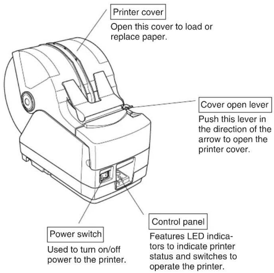
5-1. Control Panel
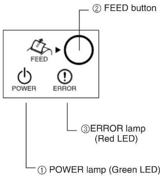
①POWER lamp (Green LED) Lights when the power is ON
②FEED button Press the FEED button to feed roll paper.
③ERROR lamp (Red LED) Indicates various errors in combination with POWER lamp
5-2. Errors
(1) Automatically recoverable error
| Error Description | POWER lamp | ERROR lamp | Recovery Conditions |
| Head high temperature detection | Flashes at 0.5 second intervals | Off | Automatically recovered after the print head has cooled. |
| Cover open error | On | On | Automatically recovered by closing the printer cover. |
(2) Recoverable error
| Error Description | POWER lamp | ERROR lamp | Recovery Conditions |
| Paper cut error | Off | Flashes at 0.125 second intervals | Recovered If the cutter returns to the home position after turning the power OFF and ON. |
Note:
1) If the cutter doesn't return to the home position, or doesn't perform the initial movement, it cannot be recovered.
2) If the paper is jammed, turn the power off, clear the jammed paper, then turn the power ON.
| Error Description | POWER lamp | ERROR lamp | Recovery Conditions |
| RAM error | Off | Flashes at 1.0 second intervals | This is not a recoverable error.Consult dealer for repairs. |
| EERROM error | Off | Flashes at 0.75 second intervals | This is not a recoverable error.Consult dealer for repairs. |
| Flash ROM error | Off | Flashes at 0.5 second intervals | This is not a recoverable error.Consult dealer for repairs. |
| Thermistor error | Off | Flashes at 1.5 second intervals | This is not a recoverable error.Consult dealer for repairs. |
| Power supply error | Off | Flashes at 2 second intervals | This is not a recoverable error.Consult dealer for repairs. |
Note:
1) If a non recoverable error occurs, turn the power OFF immediately.
2) When Power supply error occurs, there is a possibility that the power supply unit has a trouble.
For other non recoverable errors, please consult the dealer for repairs.
(4) Paper detection error
| Error Description | POWER lamp | ERROR lamp | Recovery Conditions |
| Paper out error | On | Flashes at 0.5 second intervals | Automatically recovered by loading a new paper roll, then closing the printer cover. |
| Paper near end | On | Flashes at 2 second intervals | Indicators show that the paper end is approaching, but the printer continues to print. |
5-3. Self Printing
(1)Test Printing
Turn the power on while holding the FEED button depressed.
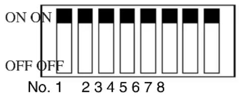
Test printing will be performed according to the Ver. No., DIP switch settings and memory switch settings.
*** TSP1000 Ver1.00
Interface : Parallel
DIP Switch 1
Sw 12345678
On *******
Off
(2) Hexadecimal Dump Mode
Open the printer cover, then turn the power on while holding the FEED button. When the cover is closed, “*** HEX DUMP PRINTING ***” is printed, and the printer enters the Hexadecimal Dump Mode.
Each of the signals sent from the computer to the printer will be printed out in hexadecimal code.
This function allows you to check if a control code sent to the printer by the program being used is correct or not. The final line is not printed if its data is less than one full line. However, if the FEED button is pushed, the final line is printed. To turn off the mode, it is necessary to turn off the printer completely.
| *** HEX DUMP PRINTING *** | |||||||
| 20 | 21 | 22 | 23 | 24 | 25 | 26 | 27 |
| 28 | 29 | 2A | 2B | 2C | 2D | 2E | 2F |
| 30 | 31 | 32 | 33 | 34 | 35 | 36 | 37 |
| 38 | 39 | 3A | 3B | 3C | 3D | 3E | 3F |
| 40 | 41 | 42 | 43 | 44 | 45 | 46 | 47 |
| 48 | 49 | 4A | 4B | 4C | 4D | 4E | 4F |
| 50 | 51 | 52 | 53 | 54 | 55 | 56 | 57 |
6. Loading the Roll Paper
6-1. Loading the Roll Paper
Loading the roll paper in this printer differs according to the type of paper (drop-in roll paper or roll paper that requires the shaft). Load the roll paper according to the procedures on the section 6-2.
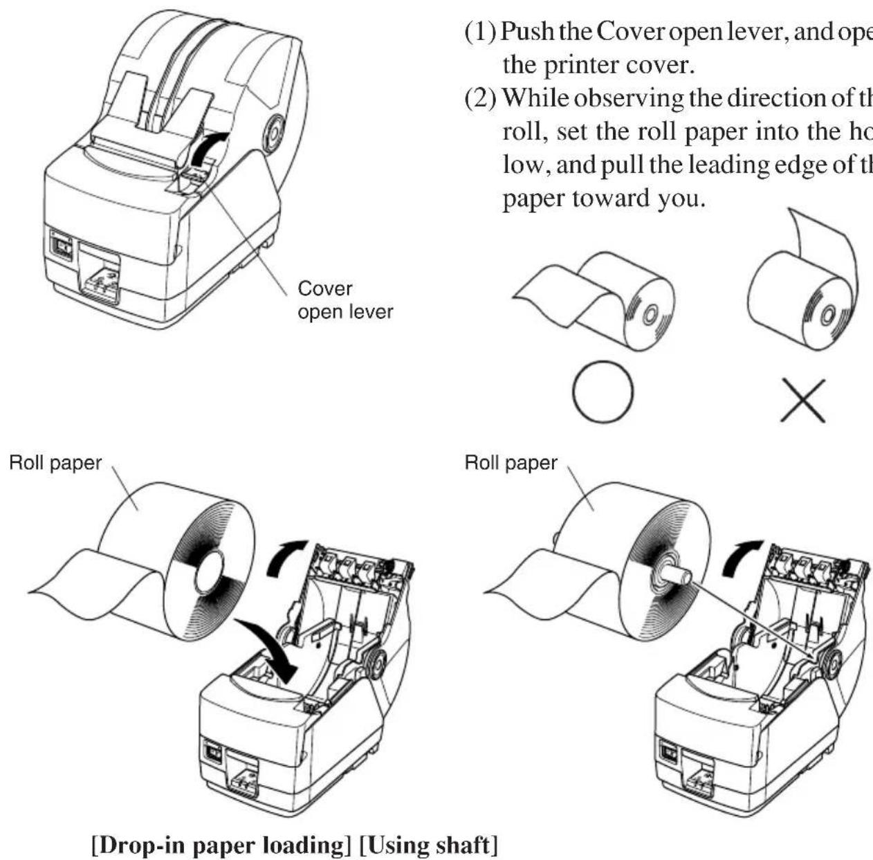
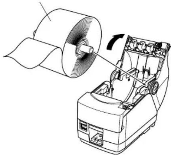
(1) Push the Cover open lever, and open the printer cover.
(2) While observing the direction of the roll, set the roll paper into the hollow, and pull the leading edge of the paper toward you.
natural_image
Line drawing of a printer with arrows indicating motion or operation (no text or symbols)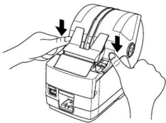
natural_image
Line drawing of hands operating a mechanical device with arrows indicating process (no text or symbols)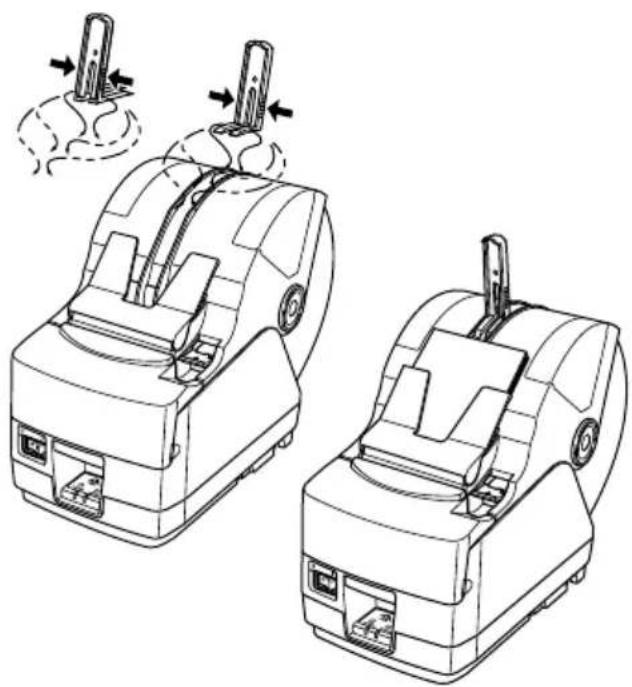
natural_image
Technical line drawing of two mechanical device assemblies with arrows indicating motion or assembly (no text or symbols)
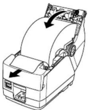
(3) Pull on the edge of the paper to remove any slack and then push down both sides of the printer cover to close it.
Note: Make sure that the printer cover is securely closed.
(4) If the printer cover is closed after turning on the power, the cutter operates automatically and the front end of the paper is cut.
Note: If the cutter does not operate after the printer cover is closed, open the cover and close it again securely.
(5)If necessary, attach the paper stopper to the paper cover as shown. The output tray can hold up to 30 sheets (width:80-82.5 mm, thickness: 80–120 μm, length: 50–150 mm). For paper with a different thickness or for other sheet lengths, the limit is 10 sheets.
Note: When attaching the paper stopper to the paper cover, position the stopper according to the length of the cut paper. (Refer to the following table.)
| Paper length (mm) | |
| Position 1 50 – 100 | |
| Position 2 100 – 120 | |
| Position 3 120 – 140 | |
| Position 4 140 – 160 | |
| Position 5 160 – 180 | |
| Position 6 180 – 200 | |
WARNING
- Do not touch the cutter blade.
- There is a cutter inside the paper outlet slot. Not only should you not put your hand in the paper outlet slot while printing is in progress, never put your hand into the outlet even when printing is not in progress.
- The printer cover can be opened when replacing the paper. However, since the cutter blade is on the inside of the printer cover, be careful not to place your face or hands too close to the cutter blade.
- During and immediately after printing, the area around the thermal head is very hot. Do not touch it, as you could be burned.
CAUTION
- Do not operate the cover open lever while pressing on the printer cover with your hand.
- Do not pull out paper while the printer cover is closed.
- The heating element and the driver IC of the thermal head are easily damaged. Do not touch them with metal objects, sandpaper, etc.
- Printing quality may suffer if the thermal head heating element becomes soiled by being touched with your hands. Do not touch the thermal head heating element.
- There is a risk of damage to the driver IC of the thermal head from static electricity. Never directly touch the IC.
- The printing quality and working life of the thermal head cannot be guaranteed if any paper other than that recommended is used. In particular, paper containing [Na+, K+, C1-] may drastically reduce the working life of the thermal head. Please exercise caution.
- Do not operate the printer if there is moisture on the front surface of the head from condensation, etc.
6-2. Paper Loading Methods
This printer has two paper loading methods: one when using the roll paper shaft, and one when not using the shaft. The roll paper shaft is not used for drop-in paper loading. Select the paper loading method from the following table according to the type of paper used.
| Paper width (mm)Paper thickness (μm) | 44.5 ≤ Width < 79.5 | 79.5 ≤ Width ≤ 82.5 |
| 65 ≤Thickness < 80 Use roll paper shaft (*1, *4) Use roll paper shaft (*2) | ||
| 80 ≤Thickness ≤20 Use roll paper shaft (*1, *4) Use drop-in loading (*3) | ||
| 120 < Thickness ≤ 150 Use roll paper shaft (*1) Use roll paper shaft (*1) | ||
Note:
*1: Maximum outer roll diameter: 150 mm
*2: Maximum outer roll diameter: 170 mm
*3: Maximum outer roll diameter: 180 mm
*4: The print speed must be changed from the high speed (factory default setting) to the middle speed (140 mm/sec.). To change the print speed, use the print speed settings command
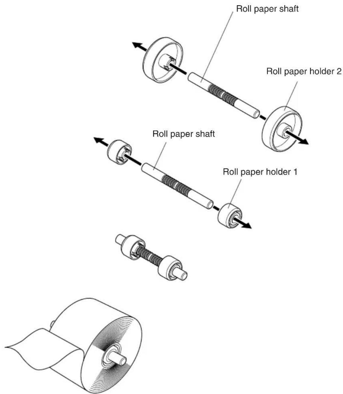
6-3. Roll Paper Holder Adjustment
There are two different sized roll paper holders: roll paper holders 1 for paper that has a one-inch inner core diameter, and roll paper holders 2 for paper that has a two-inch inner core diameter. Select the roll paper holders according to the size of roll paper used.
(1) Install the roll paper holders onto both ends of the roll paper shaft.
(2)Adjust the positions of the roll paper holders according to the width of the roll paper used.
(3)Insert the roll paper holders and shaft into the roll paper.
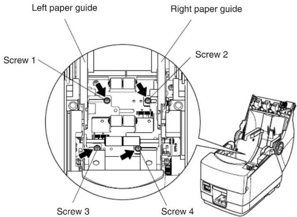
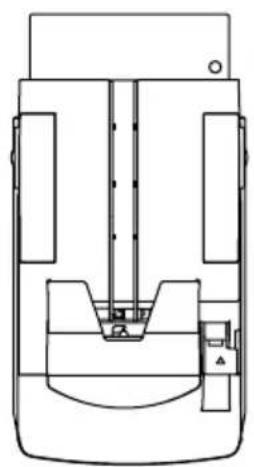
6-4. Paper Guide Adjustment
When the printer is shipped from the factory, the paper guides and upper guides are adjusted for roll paper with the following width.
Paper width: 79.5 ± 0.5 mm (TSP1043)
Paper width: 82.5 ± 0.5 mm (TSP1045)
When using roll paper with a width other than listed above, perform the following procedure to adjust the paper guides. To adjust the upper guides, refer to “6-5 Upper Guide Adjustment”.
(1)Loosen the four screws.
(2)Adjust the left and right paper guides according to the width of the roll paper, making sure to leave approximately 0.5 mm of space between each guide and the edge of the paper.
The scales on the metal plate inside the printer are divided into 1 mm segments between the ♦ marks. The two ▼marks above the scales are used for 57.5 mm wide paper and the two ♦ marks are used for 79.5 mm wide paper. Accordingly, for roll paper with a width of 79.5 mm, position each paper guide 0.5 mm to the outside of the respective ♦ mark. If necessary, screws 2 and 3 can be removed and installed in the adjacent screw holes.
(3)Tighten the four screws.
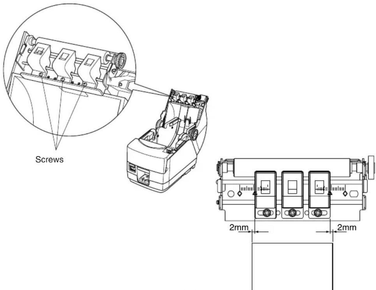
6-5. Upper Guide Adjustment
When the printer is shipped from the factory, the upper guides are adjusted for roll paper with a 79.5–82.5 mm width. When using roll paper with a different width, perform the following procedure to adjust the upper guides.
(1)Loosen the two screws for the left and right upper guides.
(2)Adjust the left and right upper guides according to the width of the roll paper, making sure that each guide is approximately 2 mm to the inside of the edge of the paper.
The scales on the metal plate on the cover are divided into 1 mm segments. The two ▲ marks below the scales are used for 57.5 mm wide paper and the two ♦ marks are used for 79.5 mm wide paper (also used for 82.5 mm wide paper). If necessary, the screws for the left and right upper guides can be removed and installed in the adjacent screw holes. If the roll paper width is 50 mm or less, remove the center upper guide by removing its screw, and then adjust the left and right upper guides.
Note:
When adjusting the upper guides, be careful not to pinch or apply unnecessary force to the wires.
(3) Tighten the two screws.
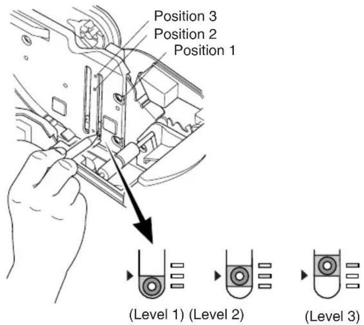
7. Adjusting the Near-end Sensor
Use the following procedure to adjust the near-end sensor so it is compatible with the size of roll paper you are using.
①Open the printer cover.
②Determine the correct position of the adjuster from the following three positions according to the paper loading method and the inner core diameter of the roll paper.
Position 1: Using drop-in paper loading
Position 2: Using roll paper holder 2 (ø50.8 mm inner core)
Position 3: Using roll paper holder 1 (ø25.4 mm inner core)
③Insert the tip of a ballpoint pen or similar object into the hole of the adjuster, and then push and slide the adjuster to the desired position.
The amounts of remaining paper that can be detected are shown in the following table.
(1) Position 1
| Paper thickness (μm) | When using roll paper with an inside core diameter (A): φ25.4 and outside core diameter (B): φ40 | |||||
| Detected diameter (C)(Approx. mm) | Remaining paper length(Approx. m) | |||||
| Level 1 Level 2 Level 3 Level 1 Level 2 | Level 3 | |||||
| 80 | φ44 φ48 | φ52 | 3.5 7.5 12.5 | |||
| 105 | 1.5 4.5 75 | |||||
(2) Position 2
| Paper thickness (μm) | When using roll paper with an inside core diameter (A): φ25.4 and outside core diameter (B): φ40 | |||||
| Detected diameter (C)(Approx. mm) | Remaining paper length(Approx. m) | |||||
| Level 1 Level 2 Level 3 Level 1 Level 2 Level 3 | ||||||
| 65 | — | φ45 | — | — | 5.6 | — |
| 80 | 4.4 | |||||
| 105 | 3.2 | |||||
(3)Position 3
| Paper thickness (μm) | When using roll paper with an inside core diameter (A):ø 50.8 and outside core diameter (B):ø58 | |||||
| Detected diameter (C)(Approx. mm) | Remaining paper length(Approx. m) | |||||
| Level 1 Level 2 Level 3 Level 1 Level 2 Level 3 | ||||||
| 150 | — | ø69 | — | — | 6.5 | — |
Note:
1) The adjuster is set to position 1, level 2 prior to being shipped from the factory.
2) The C dimension and the remained paper length are the calculated values. There may be some variations in actual mechanism.
3) The remaining paper lengths shown in the table above are for reference only. Adjust the near-end sensor to suit the actual conditions of use.
4) If thick paper is used (100 m or greater paper thickness) when the adjuster is set to position 1, there will be looseness in the roll paper itself which makes it easier for detection variations to occur. Set to Level 3.
8. Preventing and Clearing Paper Jams
8-1. Preventing Paper Jams
The paper should not be touched during ejection and before it is cut.
Pressing or pulling the paper during ejection may cause a paper jam, paper cutting failure or line feed failure.
8-2. Removing Paper Jam
If a paper jam occurs, clear it as described below.
(1) Set the power switch to off to turn off power to the printer.
(2)Push the cover open lever, and open the printer cover.
If the printer cover will not open on auto cutter models, it means that the auto cutter is not at the home position. In this case, return the auto cutter to the home position by following the instructions provided in section 8-3. Then open the printer cover after the paper jam has been removed.
(3)Remove the jammed paper.
CAUTION
Take care not to damage the printer when removing the jammed paper. Since it is easy to damage the thermal head in particular, take care not to touch it.
(4) Position the roll paper straight and close the printer cover gently.
Note:
1) Make sure that the paper is positioned straight. If the printer cover is closed with the paper skewed, a paper jam may result.
2) Lock the printer cover by pressing down both sides. Make sure that the printer cover is securely closed.
(5) Set the power switch to on to turn on power to the printer. Make sure that the ERROR LED is not lit.
Note: While the ERROR LED is lit, the printer will not accept any commands such as the print command, so make sure that the printer cover is locked properly.
8-3. Releasing a Locked Cutter
If the auto cutter locks up or fails to cut the paper, follow the steps below.

WARNING
Since working on the cutter may be dangerous, be sure to turn off the printer first.
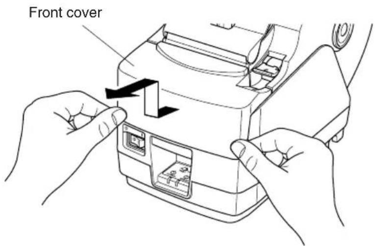
(1) Set the power switch to OFF to turn off the printer.
(2)Slide off the front cover to reveal the auto cutter.
(3)Remove any jammed paper.

CAUTION
Be careful not to damage the printer while removing any jammed paper. Since the thermal print head is particularly sensitive, be sure not to touch it.
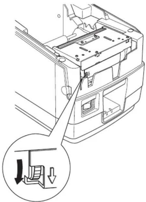
(4) If the cutter's moving blade is protruding, rotate the knob in the direction of an arrow to return the moving blade to its home position.
When the check window is completely white, the moving blade is at its home position.
CAUTION
1) Do not apply extreme pressure to the moving blade.
2) If the moving blade is protruding too much, the printer cover cannot be opened. Trying to open the printer cover may damage the cutter.
(5)Open the printer cover, remove any jammed paper, and then re-install the paper roll.
(6) Install the front cover, and then set the power switch to ON.
natural_image
Technical line drawing of a mechanical component with an inset showing a downward force or compression mechanism (no text or symbols present)9. Periodical Cleaning
Printed characters may become partially unclear due to accumulated paper dust and dirt. To prevent such a problem, paper dust collected in the paper holder and paper transport section and on the surface of the thermal head must be removed periodically. Such cleaning is recommended to be carried out once six month or one million lines.
9-1. Cleaning the Thermal Head
To remove blackish dust collected on the surface of the thermal head, wipe it with Isopropyl alcohol (IPA).
Note: The thermal head is easy to damage, so clean it gently with a soft cloth. Take sufficient care not to scratch it when cleaning it.
9-2. Cleaning the Paper Holder
Use a soft cloth to remove paper dust from the paper holder and paper transport section.
TABLE DES MATIERES
Mitsubishi paper mills limited
Kanzaki Specialty Papers Inc. (KSP)
natural_image
Diagram showing a mechanical assembly before and after transformation, with no visible text or symbols.natural_image
Technical line drawing of a mechanical device with mounting base and internal components (no text or symbols)natural_image
Technical line drawing of a mechanical device connected to a power strip and cable, with an inset showing a close-up of the component (no text or symbols present)ATTENTION
natural_image
Line drawing of a mechanical device with no visible text or symbolsnatural_image
Technical line drawing of a mechanical assembly with no visible text or symbols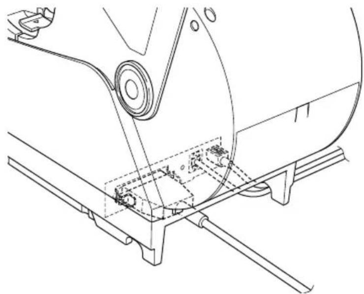
natural_image
Technical line drawing of a mechanical assembly with no visible text or symbols
natural_image
Technical line drawing of a mechanical assembly with mounting brackets and a central component (no text or symbols)natural_image
Line drawing of a handheld device with an inset showing a small component being inserted (no text or symbols present)natural_image
Technical illustration of a mechanical device with a spool and internal components, showing no text or symbols.natural_image
Line drawing of a printer with directional arrows indicating motion (no text or symbols)natural_image
Simple line drawing of a rolled-up document and a circle (no text or symbols)
natural_image
Simple line drawing of a rolled paper or scroll with a cross mark below (no text or symbols)Rouleau de papier
natural_image
Technical line drawing of a mechanical device with a rotating shaft and internal components (no text or symbols)natural_image
Line drawing of hands operating a mechanical device with arrows indicating process (no text or symbols)
natural_image
Technical line drawing of two mechanical device assemblies with arrows indicating motion or assembly (no text or symbols)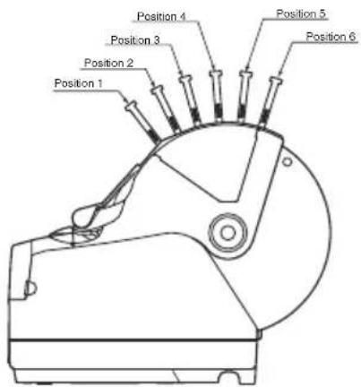
natural_image
Technical line drawing of a mechanical component with a curved handle and central shaft (no text or symbols)natural_image
Technical line drawing of a mechanical assembly with an inset showing a downward force application (no text or symbols present)9. Nettoyage
Kanzaki Specialty Papers Inc. (KSP)
Lotto482 (tickets), 84 μm (Dicke)
natural_image
Diagram showing a mechanical assembly before and after transformation, with no visible text or symbolsnatural_image
Technical line drawing of a mechanical device with mounting base and internal components (no text or symbols)natural_image
Technical line drawing of a mechanical device connected to a power strip and cable, with an inset showing a close-up of the component (no text or symbols present)! ACHTUNG
natural_image
Technical line drawing of a mechanical assembly with no visible text or symbols
natural_image
Technical line drawing of a mechanical assembly with no visible text or symbols
natural_image
Technical line drawing of a mechanical assembly with mounting brackets and a central circular component (no text or symbols)natural_image
Line drawing of a handheld device with an inset showing a small component being inserted (no text or symbols present)natural_image
Line drawing of a printer with directional arrows indicating motion (no text or symbols)
natural_image
Line drawing of hands operating a mechanical device with arrows indicating process (no text or symbols)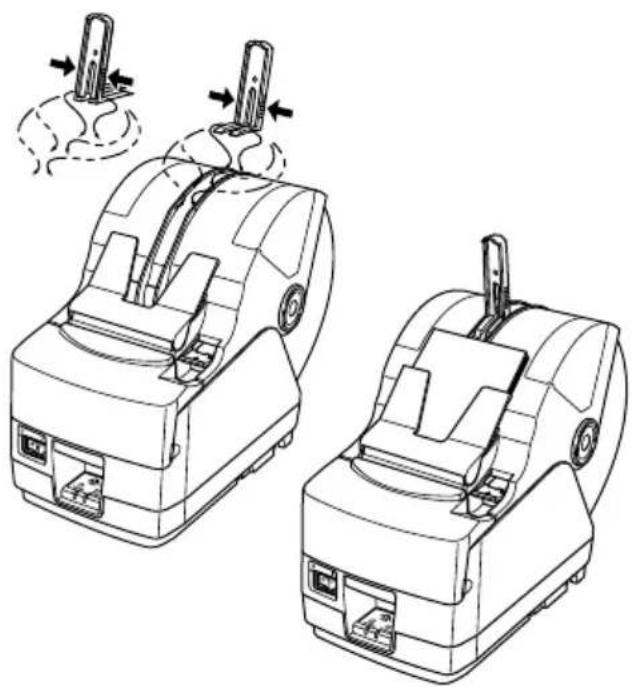
natural_image
Technical line drawing of two mechanical device assemblies with arrows indicating motion or assembly (no text or symbols)
natural_image
Technical line drawing of a mechanical component with an inset showing a downward arrow indicating a process or assembly (no text or symbols present)Mitsubishi Paper Mills Limited
Kanzaki Specialty Papers Inc. (KSP)
Uscita: 24±5%CC, 2,0 A (5,0 A carico 10 sec. mass.)

CAUTELA
natural_image
Diagram showing a mechanical assembly before and after transformation, with no visible text or symbols.4-1-4. Collegamento del cavo Ethernet
natural_image
Technical line drawing of a mechanical device with mounting base and internal components (no text or symbols)natural_image
Technical line drawing of a mechanical device connected to a power strip and cable, with an inset showing a close-up of the component (no text or symbols present)CAUTELA
natural_image
Technical line drawing of a mechanical device with labeled component 'zione' (no other text or symbols)natural_image
Technical line drawing of a mechanical assembly with no visible text or symbols
natural_image
Technical line drawing of a mechanical assembly with no visible text or symbols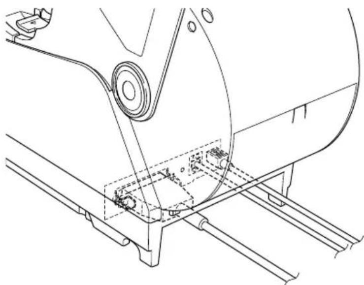
natural_image
Technical line drawing of a mechanical assembly with mounting brackets and a central component (no text or symbols)natural_image
Line drawing of a handheld device with an inset showing a close-up of its connector (no text or symbols present)natural_image
Technical illustration of a mechanical device with a magnified view showing internal components and motion arrows (no text or symbols)natural_image
Technical line drawing of a mechanical device with a rotating shaft and internal components (no text or symbols)natural_image
Line drawing of a mechanical device with directional arrows indicating motion or movement (no text or symbols)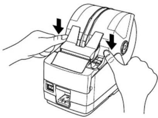
natural_image
Line drawing of hands operating a mechanical device with arrows indicating process (no text or symbols)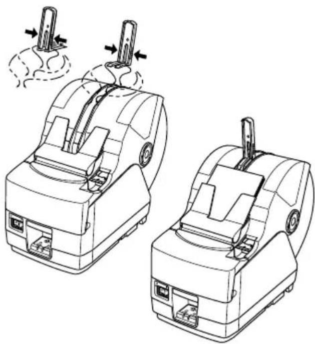
natural_image
Technical line drawing of two mechanical device assemblies with arrows indicating motion or assembly (no text or symbols)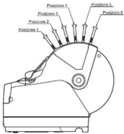
natural_image
Line drawing of a cylindrical mechanical component with a flanged end and central shaft (no text or symbols)natural_image
Technical line drawing of a mechanical component with an inset showing a downward force or compression mechanism (no text or symbols present)Appendix A: Specifications
A-1. General Specifications
(1)Printing method Direct line thermal printing
(2)Print speed Max. 1440 dots/sec. (180 mm/sec.)
(3)Dot density 203 dpi: 8 dots/mm (0.125 mm/dot)
(4)Printing width Factory default : 72 mm (TSP1043)
: 80 mm (TSP1045)
(5)Number of print columns
$$ 5 3 (1 2 \times 2 4 \text { dots }) $$
(6)Roll paper Refer to chapter 3 for details on the recommended roll paper.
(7) Overall dimension 161 (W) × 307 (D) × 249 (H) mm
(8)Weight Approx. 3.0 kg
(9)Noise Approx. 57 dB
natural_image
Technical line drawing of a mechanical component with no visible text or symbols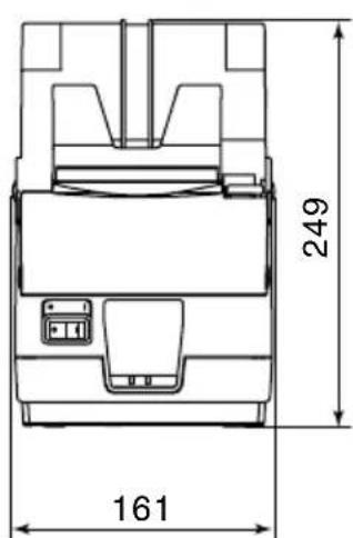
natural_image
Technical line drawing of a mechanical component with dimension标注 (307), no readable text or symbols present.Unit : mm
A-2. Auto Cutter Specifications
(1)Cutting frequency Max. 20 cuts per minute
(2)Thickness of paper 0.065 \~ 0.150 mm
A-3. Interface
RS232C serial interface/Two-way parallel interface (IEEE1284)/USB interface/Ethernet interface/Wireless LAN Interface
A-4. Electrical Characteristics
(1) Input Voltage DC 24V±10%
(2) Current Consumption Operating: Approx. 2.0 A (at ASCII printing)
Peak: Approx. 10 A
Stand-by: Approx. 0.1 A
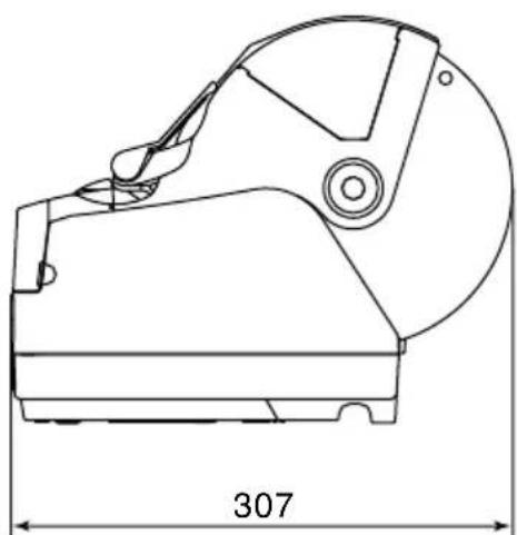
(3)Power Connector
| Pin No. | Function |
| 1 Drive power | |
| 2 Signal GND | |
| 3 N.C. | |
| Shell Frame ground | |
Note:
- When using a printer power supply other than the optional AC adaptor (PS60), be sure that the following cautions are observed.
- Use a power supply of DC 24 V ±10% and more than 2.0 A (5.0 A Load 10 sec. Min) with SELV output approved by IEC60950.
- Be careful about installing the printer in an area where there is noise. Take the appropriate measures to protect against electrostatic AC line noise, etc.
A-5. Option
(1) USB Interface Board Unit (IFBD-HU04)
(2) Parallel Interface Board Unit (IFBD-HC04)
(3) 25 Pin RS-232C Interface Board Unit (IFBD-HD04)
(4) 9 Pin RS-232C Interface Board Unit (IFBD-HN04)
(5) Ethernet Interface Board Unit (IFBD-HE04)
(6) Wireless LAN interface Board Unit (IFBD-HW04)
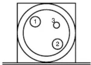
A-6. Environmental Requirements
(1)Operating
Temperature 5°C to 45°C
Humidity 10% to 90% RH (without condensation)
line
| Operating temperature (°C) | Relative humidity (%RH) | | -------------------------- | ------------------------ | | 0 | 10 | | 50 | 90 | | 50 | 65 | | 50 | 50 |(2)Transport/storage (except for paper)
Temperature -20^ to 60^
Humidity 10% to 90% RH (without condensation)
A-7. Reliability
(1)LIFE 20 million lines (based on an average printing rate of 12.5% with paper thickness in the range 80~ to 85 m )
(2) Cutter life 1.0 million cuttings (if the paper thickness is 100 m or less)
0.3 million cuttings (if the paper thickness is more than 100 m)
A-8. Black Mark Specifications
When using the paper-end sensor as a black mark sensor, the following settings are recommended.
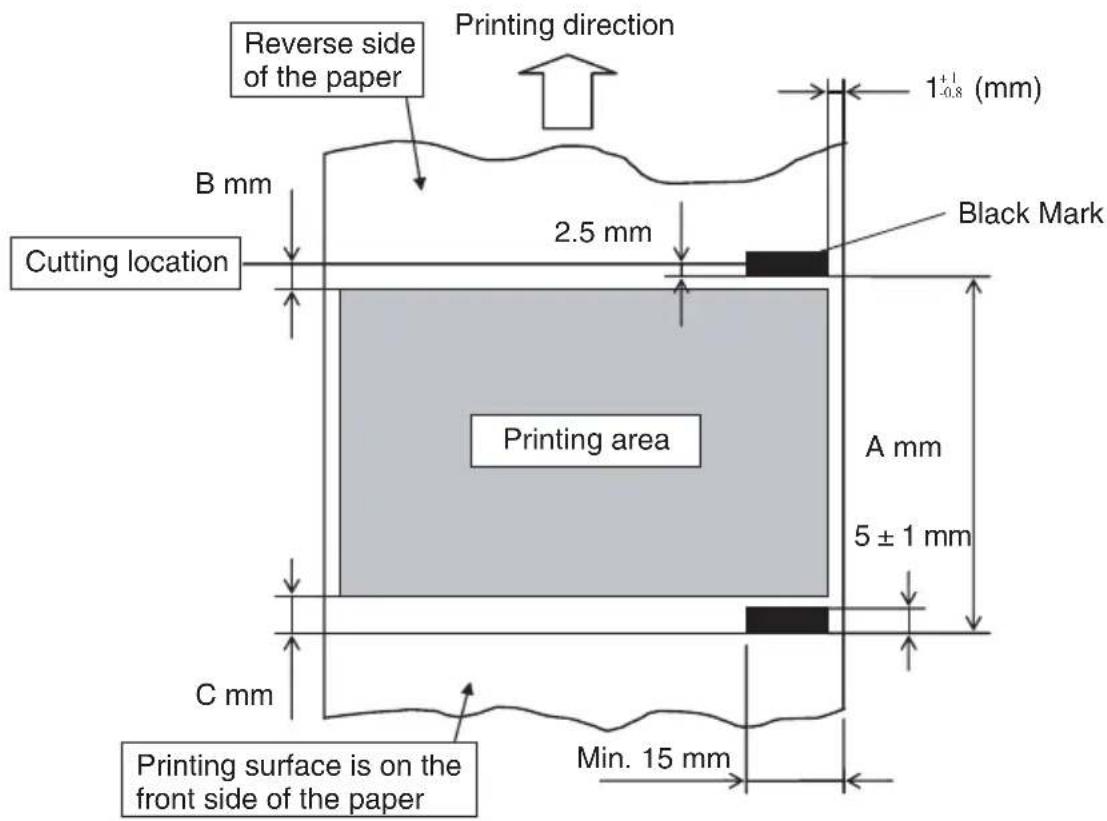
Note:
The paper is cut at the location shown above when the memory switch is set to the default setting for the printing start location offset value.
- Black mark pitch (dimension A)
Dimension A for the black mark pitch can be set to 50–300 mm.
Note:
Although the black mark pitch can be set in the range listed above, it is recommended that you consider the variations that occur with the printing location when setting the print layout.
- Black mark dimensions
Refer to the above figure for the dimensions of the black marks that will be printed.
3. PCS value
The PCS value of the black marks that will be printed should be a minimum of 0.90 (90%).
Note:
If the PCS value of the black marks does not meet the specification listed above, page skipping and page length detection errors may occur. To avoid problems, make sure that the specified PCS value is used.
4. Top margin (dimension B)
When setting the printing area, leave a sufficient top margin between the cutting location and the top of the printing area.
When not using reverse paper feeding, a top margin of at least 12 mm is recommended: 11 mm for the distance between the thermal head heating element and the cutting location, and 1 mm for the paper feeding that occurs due to the vibrations when the motor starts.
Note:
1) If the top margin is insufficient, page skipping errors may occur. To avoid problems, set the top margin carefully.
2) The printing area setting should not exceed the black mark pitch.
5. Bottom margin (dimension C)
When setting the printing area, leave a sufficient bottom margin between the bottom of the printing area and the following black mark.
When setting the bottom margin, consider the printing precision of the black mark pitch, TOF printing precision ( ±2 mm from the standard printing location), ambient temperature at the installation location, and the amount of wear of the printer parts. It is recommended to set the printing area to achieve the following bottom margin.
Bottom margin (dimension C) ≥ 3 mm + (dimension A × 3%)
Note:
1) If the bottom margin is insufficient, page skipping errors may occur. To avoid problems, set the bottom margin carefully.
2) The printing area setting should not exceed the black mark pitch.
- Example of printing area setting
An example of the settings for the printing area when not using reverse paper feeding is shown below.
Black mark pitch (dimension A): 100 mm
Top margin: 12 mm
Bottom margin: 3 mm + (100 mm × 0.03) = 6 mm
Given the above settings, the printing area must be set to 82 mm or less (100 mm - 12 mm - 6 mm = 82 mm).
Note:
1) Be careful when setting the print layout for pre-printed paper. The TOF printing precision when detecting black marks is ±2 mm from the standard printing location. In addition, the printing length is ±2% of the set value according to variations with the initial ambient temperature and platen diameter precision, and a margin of error of up to -5% may occur according to the life of the printer.
2) If you have any questions regarding how to set the printing area according to the black mark pitch, contact Star Micronics.
- Sensor adjustment
When using black marks, it is recommended to adjust the black mark sensor.
Appendix B: Dip Switch Setting
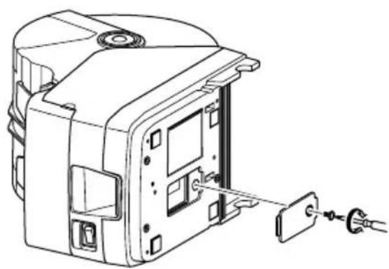
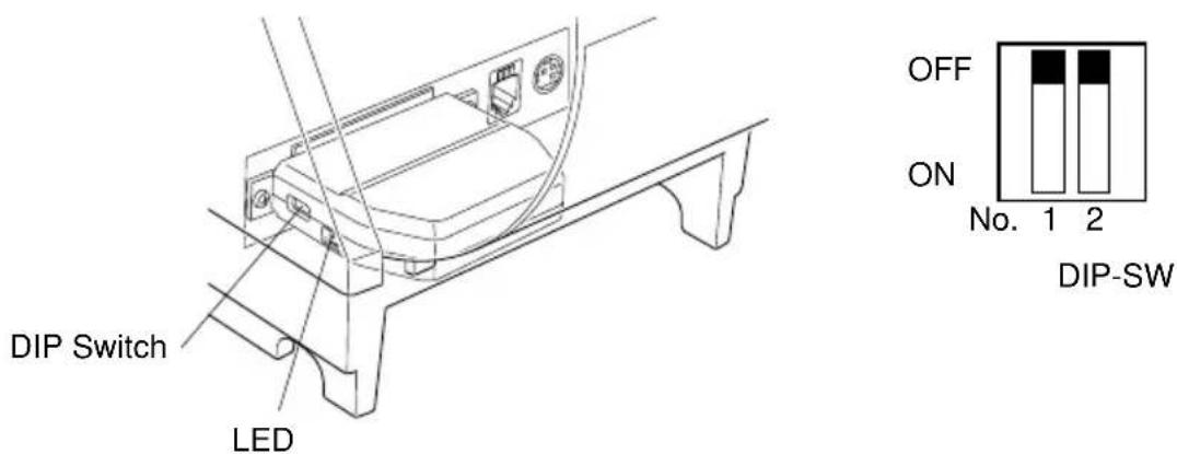
Two DIP switches are provided at the bottom of the printer, and can be set as given in the table below. Be sure to set the power switch to off before changing the settings. It is recommended to use a pointed item like a pen or flat-blade driver screw to change the settings. The settings will become effective when the power switch is set to on again.
The following is the procedure for changing the settings on DIP switches.
- Make sure the printer is turned off.
- Remove the screw from the DIP switch cover. Then take off the DIP switch cover, as shown in the illustration below.
natural_image
Technical line drawing of an electrical enclosure with a fuse and socket (no text or symbols)-
Set the switches using a pointed tool, such as a pen or flat-blade screwdriver.
-
Replace the DIP switch cover. Then secure it with the screw. The new settings take effect when you turn on the printer.
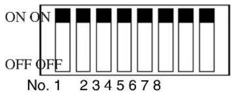
B-1. Parallel Interface Model
DIP-SW1

DIP-SW2
DIP-SW 1
| Switch | Function ON OFF | ||
| 1-1 Command emulation | See table below | ||
| 1-2 Command emulation | |||
| 1-3 | Should not be changed (Should be set to on) | ||
| 1-4 Sensor adjustment Valid Invalid | |||
| 1-5 Pin #31 (INIT) reset signal Valid Invalid | |||
| 1-6 Handshaking conditions Offline or receive Receive buffer full (conditions for BUSY) buffer full | |||
| 1-7 Automatic status back function Invalid Valid | |||
| 1-8 Should not be changed (Should be set to on) | |||
The factory settings of DIP switch are all on.
| Switch 1-1 | Switch 1-2 | Command emulation |
| ON ON | Star Line Mode | |
| OFF | ON | Star Page Mode |
| OFF | OFF | ESC/POS Mode |
DIP-SW 2
| Switch | Function ON OFF | ||
| 2-1 | Always ON | Should be set to on | |
| 2-2 | |||
| 2-3 | |||
| 2-4 | |||
The factory settings of DIP switch are all on.
B-2. Sperial Interface (RS-232C) Model

DIP-SW1

DIP-SW2
DIP-SW 1
| Switch | Function ON OFF | ||
| 1-1 | Command emulation | See table below | |
| 1-2 | Command emulation | ||
| 1-3 | Should not be changed (Should be set to on) | ||
| 1-4 | Sensor adjustment Valid Invalid | ||
| 1-5 | Should not be changed (Should be set to on) | ||
| 1-6 | Handshaking conditions Offline or receive Receive buffer full (conditions for BUSY) buffer full | ||
| 1-7 | Automatic status back function Invalid Valid | ||
| 1-8 | Should not be changed (Should be set to on) | ||
The factory settings of DIP switch are all on.
| Switch 1-1 Switch 1-2 | Command emulation | |
| ON ON | Star Line Mode | |
| OFF | ON | Star Page Mode |
| OFF | OFF | ESC/POS Mode |
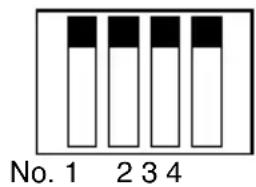
DIP-SW 2
| Switch | Function ON OFF | ||
| 2-1 | Always ON | Should be set to on | |
| 2-2 | |||
| 2-3 | |||
| 2-4 | |||
The factory settings of DIP switch are all on.
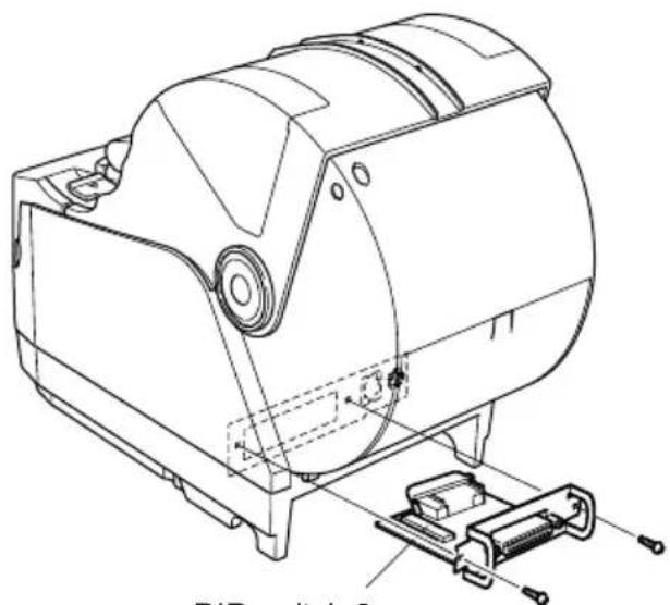
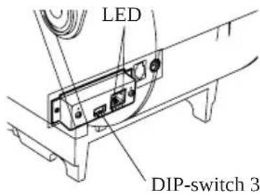
The following is the procedure for changing the settings on DIP switch No. 3.
-
Turn off the printer and all components connected to it.
-
Remove the 2 screws.
-
Remove the serial interface board unit.
-
Change the setting of the DIP switches.
-
Replace the serial interface board unit.
Then secure it with the screws.
- Turn on the printer and all components connected to it.
natural_image
Technical line drawing of a mechanical device with mounting bracket and clamping mechanism (no text or symbols)DIP switch 3
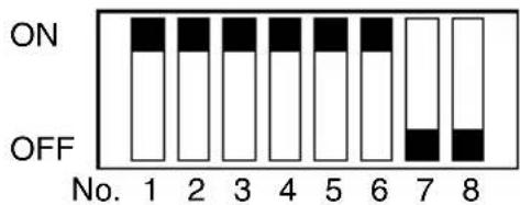
DIP-SW3
The factory settings of DIP switch are all on, except for switches 7 and 8.
DIP-SW 3
| Switch | Function ON OFF | ||
| 3-1 | Baud Rate See table below | ||
| 3-2 | |||
| 3-3 | Data Length 8 bits 7 bits | ||
| 3-4 | Parity Check Disabled Enabled | ||
| 3-5 | Parity Odd Even | ||
| 3-6 | Handshake DTR/DSR XON/XOFF | ||
| 3-7 | Should not be changed (Should be set to off) | — | — |
| 3-8 | |||
| Baud Rate Switch 3-1 | Switch 3-2 | |
| 4800BPS | OFF | ON |
| 9600BPS | ON | ON |
| 19200BPS | ON | OFF |
| 38400BPS | OFF | OFF |
B-3. USB Interface Model
DIP-SW1

DIP-SW2
DIP-SW1
| Switch | Function ON OFF | |||
| 1-1 | Command emulation | See table below | ||
| 1-2 | Command emulation | |||
| 1-3 | Should not be changed (Should be set to on) | |||
| 1-4 | Sensor adjustment Valid Invalid | |||
| 1-5 | USB mode Mode 1 (Printer class) Mode 2 (Vendor class) | |||
| 1-6 | Handshaking conditions Offline or receive Receive buffer full (conditions for BUSY) buffer fuu | |||
| 1-7 | Automatic status back function Model 1 (Should be set to on) | |||
| Model 2 | Invalid | |||
| 1-8 | Should not be changed (Should be set to on) | |||
The factory settings of DIP switch are all on.
| Switch 1-1 | Switch 1-2 | Command emulation |
| ON | ON | Star Line Mode |
| OFF | ON | Star page Mode |
| OFF | OFF | ESC/POS Mode |
Note:
1) A STAR USB Printer Driver Set is needed for using the USB interface on Windows 98 or 98SE. You can download the STAR USB Printer Driver Set from the following website.
2) Download the Mode 2 (vendor class) driver set from the following website for use.
Printer Driver URL http://www.star-m.jp/eng/dl/dl02.htm
DIP-SW 2
| Switch | Function ON OFF | ||
| 2-1~2-4 | Always ON | Should be set to on | |
The factory settings of DIP switch are all on.
B-4. Ethernet Interface Model

DIP-SW1
DIP-SW2
DIP-SW1
| Switch | Function ON OFF | ||
| 1-1 Command emulation | See table below | ||
| 1-2 Command emulation | |||
| 1-3 Should not be changed (Should be set to on) | |||
| 1-4 Sensor adjustment Valid Invalid | |||
| 1-5 Should not be changed (Should be set to on) | |||
| 1-6 Handshaking coditions Offline or receive Receive buffer full (conditions for BUSY) buffer full | |||
| 1-7 Should not be changed (Should be set to on) | |||
| 1-8 Should not be changed (Should be set to on) | |||
The factory settings of DIP switch are all on.
| Switch 1-1 Switch 1-2 | Command emulation | |
| ON | ON | Star Line Mode |
| OFF | ON | Star Page Mode |
| OFF | OFF | ESC/POS Mode |
DIP-SW 2
| Switch | Function ON OFF | ||
| 2-1~2-4 | Always ON Should be set to on | ||
The factory settings of DIP switch are all on.
DIP-SW 3
| Switch Function ON OFF | |||
| 3-1 Always OFF Should be set to off | |||
| 3-2 Initialization of settings Valid Invalid | |||
| 3-3 Always OFF Should be set to off | |||
| 3-4 | #9100 Multi-session(Maximum 8 sessions) | Valid Invalid | |
The factory settings of DIP switch are all OFF.
The firmware must be ver.2.02 or later.
■LED Display
Green : Lights when other party connection is recognized as 10BASE-T.
Orange : Lights when packets are received.
Installing the Printer Driver and the LPR Port Driver Set
To use the Ethernet interface from Microsoft's Windows 95/98 and ME, the "Star LPR Port Driver Set" along with the printer driver is necessary.
Download the Printer Driver and the Star LPR Port Driver Set from the following Web site.
Printer Driver URL : http://www.star-m.jp/eng/dl/dl02.htm
* To use Windows NT 4.0/2000/XP, the “Star LPR Port Driver Set” is unnecessary.
B-5. Wireless LAN Interface Model
| DIP Switch ON OFF | |
| 1 Fixed at OFF | |
| 2 Initialize of setting information — | |
The factory settings of DIP switch are all off.
LED Display
Green : Lights when pockets are received.
Installing the Printer Driver and the LPR Port Driver Set
To use the wireless LAN interface from Microsoft's Windows 95/98 and ME, the "Star LPR Port Driver Set" along with the printer driver is necessary.
Download the Printer Driver and the Star LPR Port Driver Set from the following Web site.
Printer Driver URL : http://www.star-m.jp/eng/dl/dl02.htm
* To use Windows NT 4.0/2000/XP, the “Star LPR Port Driver Set” is unnecessary.
Note:
- This product contains a built-in wireless device and can only be used in the following countries.
USA, UK, France, Ireland, Belgium, Germany, Austria, Switzerland, Italy, Denmark, Norway, Sweden, Portugal, Spain, Estonia, Finland, Greece, Liechtenstein, Luxem-burg, Netherlands, Canada, Slovakia, Slovenia, Czech, Hungary, Poland, Latvia, and Lithuania.
*This product contains Transmitter Module which conforms to the R&TTE Directive.
*This roduct ontains Transmitter odule FCC ID: 4B6180210.
*This roduct ontains Transmitter odule IC: 844A-66180210.
*Strictly observe the export control laws of the country for export when exporting this product.
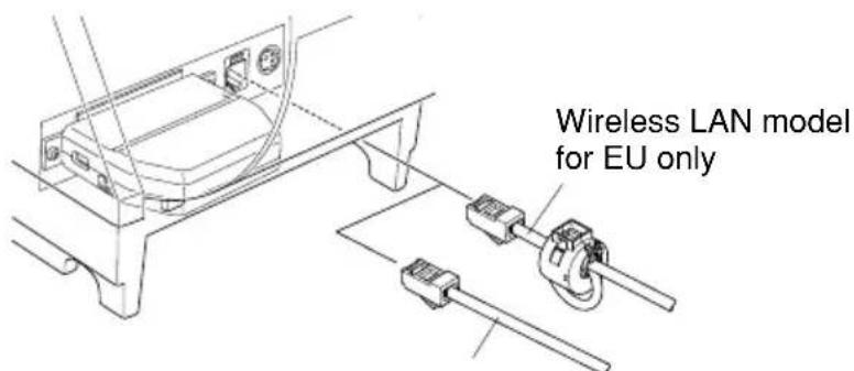
Installing the Ferrite Core (Wireless LAN Model for EU Only)
Install the ferrite core onto the buzzer drive cable to prevent radio interference. Use the ferrite core only for the wireless LAN model in the EU.
①Install the ferrite core onto the buzzer drive cable as shown in the illustration.
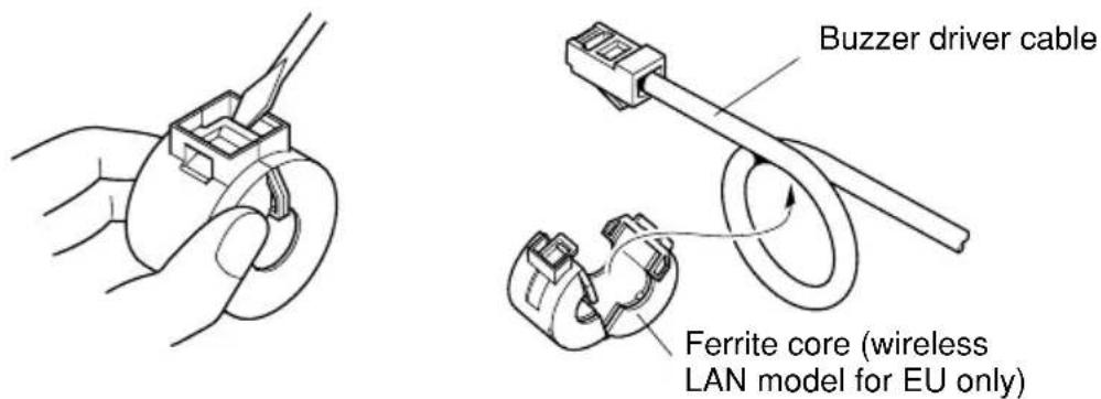
②Pass the fastener through the holes in the ferrite core as shown in the illustration.
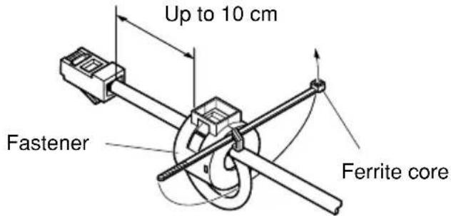
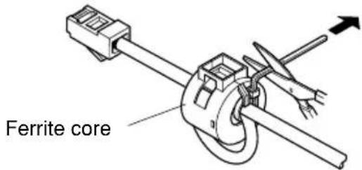
③Loop the fastener around the cable, and then pull the end of the fastener tightly through its buckle. Use a pair of scissors to cut off the excess end of the
fastener.
Connecting the buzzer drive cable
Connect the buzzer drive cable to the connector on the printer. Then, connect the other end of the cable to the buzzer drive circuit.
For other models or areas
Appendix C: Parallel Interface
The two-way parallel interface is compatible with the IEEE1284 compatibility mode and nibble mode. Refer to the separate Specification Manual for details.
Table of Connection Signals for Each Mode
| Pin No. | Direction | Compatibility Mode Signal Name Nibble | Mode Signal Name |
| 1 In n | Strobe Host | Clock | |
| 2 In/Out Data0 | Data0 | ||
| 3 In/Out Data1 | Data1 | ||
| 4 In/Out Data2 | Data2 | ||
| 5 In/Out Data3 | Data3 | ||
| 6 In/Out Data4 | Data4 | ||
| 7 In/Out Data5 | Data5 | ||
| 8 In/Out Data6 | Data6 | ||
| 9 In/Out Data7 | Data7 | ||
| 10 Out | nAck PtrClk | ||
| 11 Out | Busy PtrBusy/Data3,7 | ||
| 12 Out | PError | AckDataReq/Data2,6 | |
| 13 Out | Select | Xflag/Data1,5 | |
| 14 | — | HostBusy | |
| 15 | — | — | |
| 16 | Signal GND | Signal GND | |
| 17 | Frame GND | Flame GND | |
| 18 OUT | +5V | +5V | |
| 19~30 | Twisted Pair Return | Twisted Pair Return | |
| 31 | In | nInit | nInit |
| 32 Out | nFault | nDataAvail/Data0,4 | |
| 33 | External GND | — | |
| 34 | — | — | |
| 35 | — | — | |
| 36 | In | nSelectIn | 1284Active |
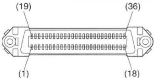
This connector mates with an Amphenol 57-30360 connector
Parallel interface connector (printer side)
Note:
1) The first letter “n” of each signal name indicates that the signal is active “L”. If any one of the above signals is not available, bidirectional communication cannot be accomplished.
2) In interfacing signals, be sure to use twist-paired wires for signal lines, and the return side must be connected to signal ground level.
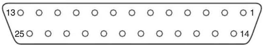
Appendix D: Serial Interface (RS-232C)
D-1. RS-232C Connector
| Pin No. | Signal name | Direction Function | ||||
| 25 Pin | 9 Pin | |||||
| 1 F-GND | — Frame ground | |||||
| 2 3 TXD OUT Transmission data | ||||||
| 3 2 RXD IN Receive data | ||||||
| 4 7 RTS OUT Same as DTR signal. | ||||||
| 5 N/C Not used | ||||||
| 8 CTS IN Status of this signal is not checked. | ||||||
| 6 6 DSR IN STAR Mode | Status of this signal is not checked.ESC/POS ModeIn DTR/DSR communication mode, indicates whether data receive from host is enabled or disabled.Space:Receive enabledMark:Receive disabled(except when transmitting data by DLE EOT, and GS a)This signal is not checked in the X-ON/X-OFF communication mode. | |||||
| 7 5 S-GND — Signal ground | ||||||
| 8~19 | 1,9 N/C Not used | |||||
| 20 | 4 DTR OUT STAR Mode | Indicates whether data receive from host is enabled or disabled.1) DTR/DSR Communication ModeSpace when receive is enabled.2) X-On/X-Off Communication ModeAlways space, except during following conditions:Period between reset and communication enabledDuring self printingESC/POS ModeIndicates whether data receive from host is enabled or disabled.1) DTR/DSR Communication ModeThis signal indicates whether the printer is busy. SPACE indicates that the printer is ready to receive data, and MARK indicates that the printer is busy. The busy condition can be changed by using DIP SW 1-6 as follows: | ||||
| Pin No. | Signal name | Direction Function | ||||
| 25 Pin | 9 Pin | |||||
| Printer status | DIP SW 1-6 | |||||
| OFF ON | ||||||
| 1. During the period from when the power is turned on (including resetting using the interface) to when the printer is ready to receive data. | BUSY BUSY | |||||
| 2. During the self printing. | BUSY BUSY | |||||
| 3. When the cover is open. | - BUSY | |||||
| 4. When the printer stops printing due to a paper-end. | - BUSY | |||||
| 5. During macro executing standby status. | - | |||||
| 6. When an error has occurred. | - | |||||
| 7. When the receive buffer becomes full. | BUSY BUSY | |||||
| 2) X-On/X-Off Communication ModeAlways space, except during following conditions:Period between reset and communication enabledDuring self printing | ||||||
| 21~24 | N/C | Not used | ||||
| 25 INIT IN Status of this signal is not checked. | ||||||
D-2. Cable Connections
The followings are a recommended interface cable connections.
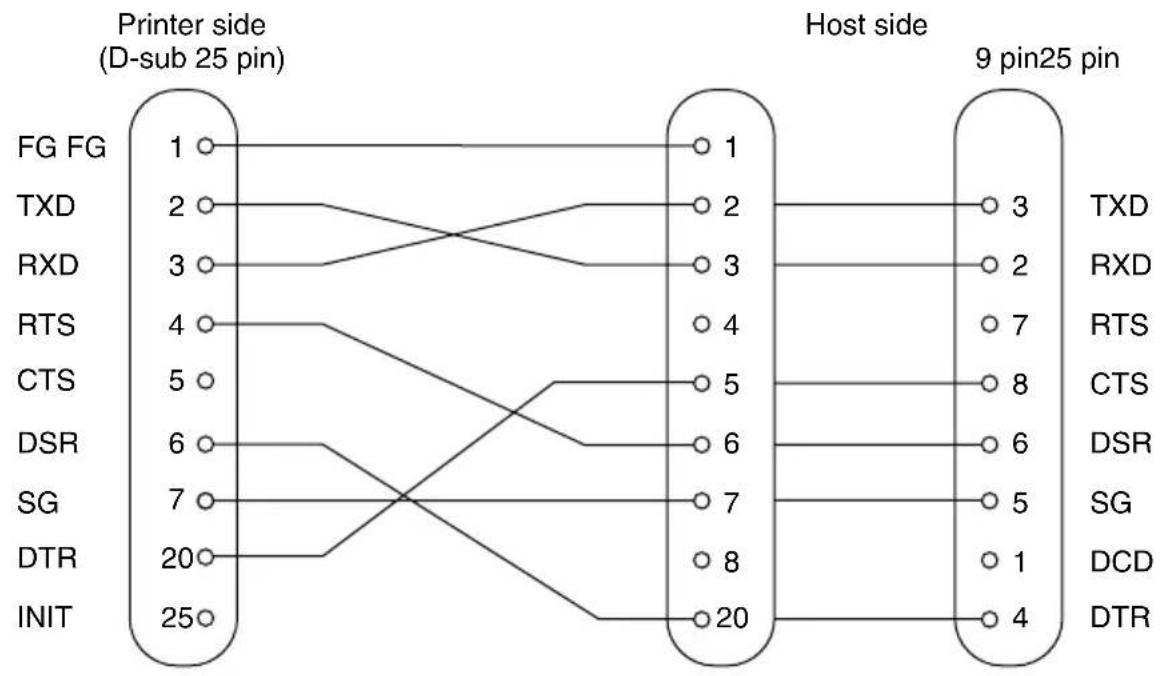
flowchart
graph LR
    subgraph_Printer_side["D-sub 25 pin"]
        FG_FG["FG FG"] --> 1
        TXD["TXD"] --> 2
        RXD["RXD"] --> 3
        RTS["RTS"] --> 4
        CTS["CTS"] --> 5
        DSR["DSR"] --> 6
        SG["SG"] --> 7
        DTR["DTR"] --> 20
        INIT["INIT"] --> 25
    end

    subgraph_Host_side["Host side"]
        1 --> 3
        2 --> 2
        3 --> 7
        4 --> 8
        5 --> 6
        6 --> 5
        7 --> 1
        8 --> 4
    end

    style Printer_side fill:#f9f,stroke:#333
    style Host_side fill:#bbf,stroke:#333
Note: Use shielded wire less than 3m in length.
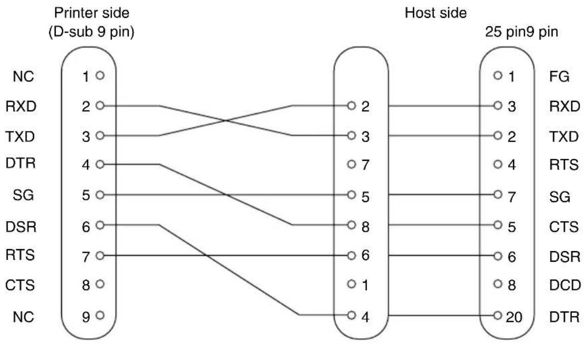
flowchart
graph LR
    subgraph Printer Side
        NC1["1"] --> RXD2["2"]
        RXD2 --> TXD3["3"]
        TXD3 --> DTR4["4"]
        DTR4 --> SG5["5"]
        SG5 --> DSR6["6"]
        DSR6 --> RTS7["7"]
        RTS7 --> CTS8["8"]
        CTS8 --> CTS9["6"]
        CTS9 --> DTR8["4"]
    end

    subgraph Host Side
        X1["2"] --> FG1["1"]
        X1 --> RXD3["3"]
        X1 --> TXD2["2"]
        X1 --> RTS4["4"]
        X1 --> SG6["7"]
        X1 --> CTS5["5"]
        X1 --> DSR6["6"]
        X1 --> DCD8["8"]
        X1 --> DTR8["20"]
    end

    style Printer Side fill:#f9f,stroke:#333
    style Host Side fill:#bbf,stroke:#333
Note: Use shielded wire less than 3m in length.
D-3. Electrical Characteristics
| Voltage Data | signal Control signal Binary status | |
| -3V to -15V Mark OFF 1 | ||
| +3V to +15V Space ON 0 |
Appendix E: USB, Ethernet and Wireless LAN Interface
E-1. USB Interface Specifications
- General Specification: Conforms to USB 2.0 Specifications
- Communication Speed: USB Full Speed Mode (12 Mbps)
- Communication Method: USB Bulk Transmission Mode
- Power Specifications: USB Self-power Function
- Connector: USB Up-Stream Port Connector (USB Type-B)
E-2. Ethernet Interface Specifications
- General Specification: Conforms to IEEE802.3
- Communication Media: 10 Base-T (Connectable to 100 Base-T)
- Communication Speed: 10 Mbps
- Protocol: TCP/IP
- TCP/IP detail: ARP, RARP, BOOTP, DHCP, LPR, #9100, IPP, POP3, HTTP, TELNET, SMTP, SNMP
- Connector: RJ-45 (8-pin modular)
E-3. Wireless LAN Interface Specifications
- General Specification: Conforms to IEEE802.1lb
- Communication Media: 2.4 GH z DSSS wireless CF card
- Communication Speed: 1M/2M/5.5M/11Mbps AUTO Full-Back
- Protocol: TCP/IP
- TCP/IP detail: ARP, RARP, BOOTP, DHCP, LPR, #9100, IPP, POP3, HTTP, TELNET, SMTP, SNMP, FTP
- Operating Channels: North America : 1-11 ch
Japan : 1-14 ch
Europe : 1-13 ch
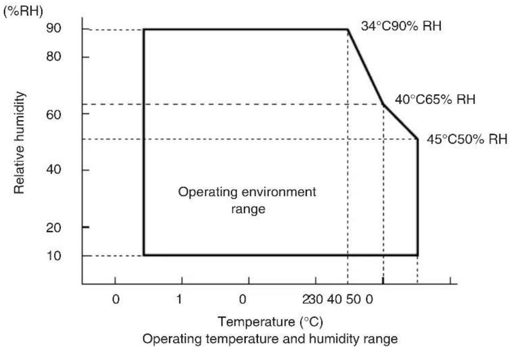
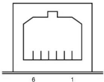
Appendix F: Buzzer Driver Circuit
This printer is equipped with a circuit for driving the buzzer. A 6-pin modular connector for connection of the buzzer is located on the back of the printer. To connect to the drive circuit, connect the buzzer to the modular connector using a cable supplied by you like that one shown in the figure below.

Caution
Never connect any other type of plug to the buzzer connector.
Modular plug
Modular plug: MOLEX 90075-0007, AMP641337, or JAPAN BURNDY B-66-4
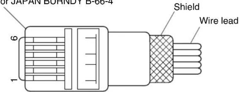
| Pin No. | Signal name direction | Function | I/O |
| 1 FG Frame ground — | |||
| 2 DRV1 Drive signal 1 OUT | |||
| 3 +24V Drive power OUT | |||
| 4 +24V Drive power OUT | |||
| 5 N.C. Not connected — | |||
| 6 N.C. Not connected — | |||
natural_image
Simple line drawing of a house-shaped structure with vertical lines inside, placed on a horizontal base (no text or symbols)
natural_image
Technical line drawing of a mechanical device with mounting base and internal components (no text or symbols)Drive circuit
The recommended drive unit is shown below.
![[ Drive Circuit ] F.G 2SD1866 M-GND +24V 7824 D1 1 2 3 4 Buzzer Drive Output: 24V, Max. 1.0A 6-P Modular jack connector Printer side ←→ User side](/content/2026/04/631534/images/47e4c7b58a3b476d9e423d659aae3d567e9030abed21ee4faf92d85e1772f70d.jpg)
Reference
2SD1866 Circuit Configuration
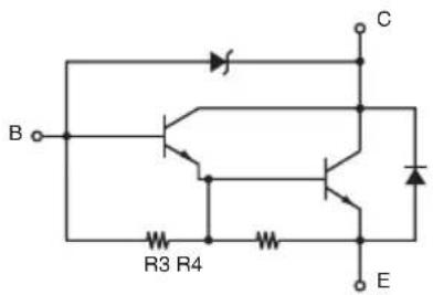
R3=3.5KΩ
R4=300Ω
Note:
1) Pin 1 must be shield drain wire connected to buzzer device frame ground.
2) For continuous driving, Maximum drive output is 0.1A.
3) Absolute maximum ratings for diodes D1 (Ta = 25°C) is:
Average Rectified Current Io = 1A
4) Absolute maximum rating for transistors 2SD1866 (Ta = 25°C) is:
Collector current Ic = 2A
Appendix G: Memory Switch Settings
Each memory switch is stored in EEPROM. For details on the functions and settings of memory switches, see the separate Specification Manual.
The table below shows the factory settings for the memory switches.
| Memory Switch Hexadecimal Code | |
| 0 0000 | |
| 1 0000 | |
| 2 0000 | |
| 3 0000 | |
| 4 | 0001(TSP1043) or 0000(TSP1045) |
| 8 0000 | |
| 9 0000 | |

CAUTION
Changing the memory switch settings can cause the printer to fail to operate correctly.
WEEE Statement
En
In the European Union, this label indicates that this product should not be disposed of with household waste. It should be deposited at an appropriate facility to enable recovery and recycling in accordance with legislation under the WEEE Directive (Directive 2002/96/EC).
Ge
natural_image
Symbol of a trash bin crossed with a diagonal line, no text or numbers present
SPECIAL PRODUCTS DIVISION STAR MICRONICS CO., LTD.
536 Nanatsushinya, Shimizu-ku, Shizuoka, 424-0066 Japan
Tel: (int+81)-54-347-0112
Fax: (int+81)-54-347-0409
Please access the following URL
http://www.star-m.jp/eng/dl/dl02.htm
for the latest revision of the manual.
OVERSEAS SUBSIDIARY COMPANIES STAR MICRONICS AMERICA, INC.
1150 King Georges Post Road, Edison, NJ 08837-3729 U.S.A.
Tel: (int+1)-732-623-5555, Fax: (int+1)-732-623-5590
STAR MICRONICS EUROPE LTD.
Star House, Peregrine Business Park, Gomm Road, High Wycombe, Bucks, HP13 7DL, U.K.
Tel: (int+44)-1494-471111, Fax: (int+44)-1494-473333
STAR MICRONICS ASIA LTD.
Rm. 1901-5, 19/F., Enterprise Square Two,
3 Sheung Yuet Road, Kowloon Bay, Hong Kong
Tel : (int+852)-2796-2727, Fax : (int+852)-2799-9344