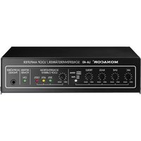
LA-40 - Receiver Monacor - Free user manual and instructions
Find the device manual for free LA-40 Monacor in PDF.


User questions about LA-40 Monacor
0 question about this device. Answer the ones you know or ask your own.
Ask a new question about this device
Download the instructions for your Receiver in PDF format for free! Find your manual LA-40 - Monacor and take your electronic device back in hand. On this page are published all the documents necessary for the use of your device. LA-40 by Monacor.
USER MANUAL LA-40 Monacor
GB Note concerning the installation of small induction loops
For small areas (e. g. information desks, reception desks, sales counters and confession boxes), the loop amplifier LA-40 can – deviating from the information in the operating instructions – be used with a shorter cable for the induction loop. The current must then be accordingly reduced with the control SCHLEIFENSTROM / LOOP CURRENT to prevent amplifier overload (the 100 % LED indicator may only flash briefly for signal peaks). The figure shows an example of a loop layout of approx. 5 m at an information desk.
text_image
MONACOR® IA-40 SCHLEIFENVERSTÄRKER / LOOP AMPLIFIER NIC UNE BASS TREBIE SCHLEIFENSTROM LOOP CURRENT BETRIEL KOMPODER ON MAX ON MAX ON MAX ON MAX ON MAX 30% 60% 100% ON MAX ON MAX ON MAX ON MAX ON MAX ON MAX ON MAX ON MAX ON MAX ON MAX ON MAX ON MAX ON MAX ON MAX ON MAX ON MAX ON MAX ON MAX ON MAX ON MAX ON MAX ON MAX ON MAX ON MAX ON MAX ON MAX ON MAX ON MAX ON MAX ON MAX ON MAX ON MAX ON MAX ON MAX ON MAX ON MAX ON MAX ON MAX ON MAX ON MAX ON MAX ON MAX ON MAX ON MAX ON MAX ON MAX ON MAX ON MAX ON MAX ON MAX ON MAX on max on max on max on max on max on max on max on max on max on max on max on max on max on max on max on max on max on max on max on max on max on max on max on max on max on max on max on max on max on max on max on max on max on max on max on max on max on max on max on max on max on max on max on max on max on max on max on max on max on max on min ON MAX ON MAX ON MAX ON MAX ON MAX ON MAX ON MAX ON MAX ON MAX ON MAX ON MAX ON MAX ON MAX ON MAX ON MAX ON MAX ON MAX ON MAX ON MAX ON MAX ON MAX ON MAX ON MAX ON MAX ON MAX ON MAX ON MAX ON MAX ON MAX ON MAX ON MAX ON MAX ON MAX ON MAX ON MAX ON MAX ON MAX ON MAX ON MAX ON MAX ON MAX ON MAX on max on max on max on max on max on max on max on max at 30% 60% 100%GB Please read these operating instructions carefully prior to operating the unit and keep them for later use. page 10
Please unfold page 3. Then you can always see the operating elements and connections described.
Contents
1 Operating Elements and Connections ..... 10
2 Safety Notes 11
3 Applications 11
4 Installation and Setting into Operation ..... 12
5 Operation 14
6 Specifications 15
1 Operating Elements and Connections
1.1 Front panel
1 Volume control for the microphone
2 Volume control for the audio source at the line input (13), e. g. TV set
3 Tone control BASS for the bass range
4 Tone control TREBLE for the high range
5 Indicator SIGNAL/PEAK; shows green if an input signal from the microphone or the audio source is available at
the line input (13); if it shows red, the input is overload -ed: in this case slightly turn back the corresponding control MIC (1) or LINE (2)
6 Control for adjusting the loop current (see chapter 4.7)
7 Indicator for the loop current
8 Power indicator
9 Headphone connection
1.2 Rear panel
10 Low-voltage jack 12 V\~/1.5 A for connection of the supplied plug-in power supply unit
11 Terminals for the induction loop
12 Terminals for a switch or momentary pushbutton for releasing a signal sound
13 Line input for connection of an audio source with line level (e.g. TV set, CD player, cassette recorder)
14 Microphone input, unbalanced 6.3 mm jack with a supply voltage for electret condenser microphones at the tip contact
2 Safety Notes
The units (amplifier and power supply unit) correspond to all required directives of the EU and are therefore marked with .
WARNING
The power supply unit is supplied with hazardous mains voltage. Leave servicing to skilled personnel only. Inexpert handling may cause an electric shock hazard.
It is essential to observe the following items:
- The amplifier and the power supply unit are suitable for indoor use only. Protect them against dripping water and splash water, high air humidity, and heat (admissible ambient temperature range 0 – 40 °C).
-
Do not set the amplifier into operation, or immediately disconnect the power supply unit from the mains socket if:
-
there is visible damage to the amplifier or the power supply unit,
- a defect might have occurred after a drop or similar accident,
- malfunctions occur.
The amplifier or the power supply unit must in any case be repaired by skilled personnel.
- For cleaning only use a dry, soft cloth, by no means chemicals or water.
- No guarantee claims for the amplifier or the power supply unit and no liability for any resulting personal damage or material damage will be accepted if the units are used for other purposes than originally intended, if they are not correctly connected, operated, or not repaired in an expert way.
If the units are to be put out of operation definitively, take them to a local recycling plant for a disposal which is not harmful to the environment.
3 Applications
The LA-40 is designed for setting up an inductive sound reproduction system for home applications. By means of a cable loop it transmits audio signals (e.g. from a TV set) to hearing aids with a "telephone coil" and to inductive receivers (e.g. LR-200 from MONACOR). Due to the wireless signal transmission the user can move freely within the loop.
The LA-40 is equipped with a dynamic compressor and is suitable for areas of 40 m² as a maximum. It allows to connect an audio source with line level (e.g. TV set, CD player) and a microphone and to adjust their volumes sepa-

rately. The microphone additionally transmits the ambient noise and words spoken in the room. This is useful if the receiver does not have an individual microphone or if the hearing aid does not allow to use its microphone and the telephone coil together (mode "MT"). Via a control input a signal sound can be triggered. A connection cable with a standard SCART plug for TV sets and a cable of 35 m length for setting up the induction loop are supplied together with the unit.
3.1 Operational principle
A cable is laid as an induction loop into the floor, the wall, or into the ceiling. Within this loop, according to the audio source, a magnetic field is created which is received with the "telephone coil" of the hearing aid or another inductive receiver and is reconverted into sound. It is possible to operate within an induction loop as many receivers as desired.
4 Installation and Setting into Operation
CAUTION
All connections should only be made by qualified personnel and in any case with the amplifier switched off.
4.1 Setting up the amplifier
Prior to setting up the amplifier glue the four self-adhesive rubber feet under the unit (as shown in figs. 1 and 2). For operation with a microphone, the amplifier should be set up outside the loop because of the increased susceptibility to acoustic feedback.
4.2 Induction loop
The LA-400 allows to realize an inductive sound reproduction system for an area of up to 40 m ^2 . As a loop, the supplied cable is laid with a single winding at the edge of the hearing area. The distance to ear level or to the receiver should be approx. 1 to 2 m. It should be avoided to lay the loop at different heights.
Magnetic fields (e. g. caused by transformers, high power cables, or fluorescent lamps) and metal parts in floors, ceilings, and walls may impair the operation of the induction loop. Therefore, prior to laying the cable definitively, make a trial run to determine the optimum loop position. When laying the induction loop in tubes, these must be made of plastic as metal tubes will affect the magnetic field of the loop.
Shorten the loop cable if it is not required in its full length, however, not shorter than 19 m, otherwise this value would
fall below the minimum load impedance which may lead to overload of the amplifier.
For connection of the loop cable, twist the cable section between the amplifier and the loop, if possible, and connect the two stripped cable ends to the terminals LOOP (11). Pay attention to a good contact so that no interfering contact resistance will result. When laying the cable, avoid any connection to earthing if the insulation is damaged.
4.3 Microphones
Connect a microphone for transmission of the ambient noise and words spoken in the room to the 6.3 mm jack MIC (14). An electret condenser microphone (e. g. ECM-300LA from MONACOR especially designed for this application) is recommended. This may e. g. be placed on a table from where it picks up ambient noise and telephone ringing best. The supply voltage required by this microphone is made available via the tip contact of the connection jack (7.2 V–via 2 kΩ).
Dynamic microphones are not suitable because of the susceptibility to feedback due to their electromagnetic operational system.
4.4 Units with line level
Connect an audio source with line output (e. g. TV set, CD player, cassette recorder) to the phono jacks LINE IN (13). For connection of a TV set, the supplied cable may be used.
4.5 Signal sound
A signal sound created in the unit may be released via a switch or momentary pushbutton (e.g. in the form of a bell knob) connected to the terminals ALERT (12). As long as the contacts are connected, the sound can be heard.
4.6 Power supply
Finally connect the low voltage plug of the power supply unit to the jack 12 V\~/1.5 A (10) and the power supply unit to a mains socket. With the connection of the power supply unit the amplifier is switched on; the power indicator ON (8) lights up. To switch the unit on and off conveniently, it is recommended to use a switchable mains socket or a master-slave socket rail which allows to switch the LA-40 automatically with the TV set.

4.7 Setting into Operation
All controls are of recessed design to prevent accidental misadjustment and can be adjusted with the supplied small screwdriver.
1) For the time being, turn the controls MIC (1) and LINE (2) and LOOP CURRENT (6) to the left stop (MIN). Turn the tone controls BASS (3) and TREBLE (4) to mid-position.
2) Switch on the audio source (e. g. TV set). Turn up the control LINE (2) so that the input level indicator (5) shows green with passages of high volume. If it shows red, slightly turn back the control as otherwise the sound will be distorted.
3) Turn up the control (6) for the loop current so that the 100 % LED of the indicator LOOP CURRENT (7) flashes with passages of high volume. If it lights up permanently, the current has been adjusted too high and the sound may be distorted; turn back the control correspondingly. If none of the three LEDs light up, check the loop for interruption.
4) With a hearing aid with "telephone coil" (mode or switch position "T") or an inductive receiver (e.g. LR-200 from MONACOR), check the reception quality and the sound within the cable loop.
5) Adjust the optimum sound with the controls BASS (3) for the bass range and TREBLE (4) for the high range.
6) If a microphone is connected to the jack MIC (14), add its sound with the control MIC (1). Only turn up the control so that the input level indicator (5) does not show red with ambient noise of high volume.
4.8 Headphones
Headphones may be connected to the 3.5 mm jack PHONES (9) to check the transmitted sound. The headphone volume depends on the adjusted loop current.
5 Operation
1) Switch on the audio source (e. g. TV set).
2) Switch on the power supply for the amplifier: Depending on the kind of the connection
- connect the plug-in power supply unit to the mains socket
or
- switch on the switch for the socket
or
– the unit has already been switched on (automatically).
The power indicator ON (8) lights up.
3) Switch on the inductive receiver or the hearing aid with "telephone coil" (mode or switch position "T" or "MT") and adjust the desired volume.
For switching off after use, proceed in reverse order.
5.1 Readjust the volume ratio
Only with a microphone connected: If the ambient noise e. g. the word spoken in the room is too low or too high compared to the audio source (e. g. TV set), readjust the microphone volume at the control MIC (1) with the supplied screwdriver.
5.2 Changing the sound
To readjust the sound, adjust the bass range with the control BASS (3) and the high range with the control TREBLE (4) in an optimum way with the supplied screwdriver.
5.3 Releasing the signal sound
Release the signal sound by pressing a momentary push-button (e. g. bell knob) connected to the amplifier.
6 Specifications
Max. loop current: ..... 2.8 A
Admissible loop resistance: 0.4 - 2 Ω
Maximum hearing area: ... 40 m²
Inputs (sensitivity/impedance, connection)
MIC: 2 mV/750 Ω, 6.3 mm jack, unbal.
microphone supply: .... 7.2 V via 2 kΩ (tip contact)
LINE: 200 mV/11 kΩ, phono, left/right
Tone control
BASS: 100 Hz, ±8 dB
HIGH: 10 kHz, ±10 dB
Frequency range: ..... 75 Hz – 7 500 Hz, ±3 dB
Power supply: 12 V\~/1.5 A via supplied power supply unit 230V\~/50Hz/22VA
Ambient temperature: ..... 0 – 40 °C
Dimensions (W × H × D): .. 175 × 45 × 102 mm
Weight: 510 g
Subject to technical modification.
All rights reserved by MONACOR® INTERNATIONAL GmbH & Co. KG. No part of this instruction manual may be reproduced in any form or by any means for any commercial use.
Dimensions (L × H × P) : .... 175 × 45 × 102 mm
Poids : 510 g