KAC142 - Gardening tool accessory KRESS - Free user manual and instructions
Find the device manual for free KAC142 KRESS in PDF.

| Product type | Garden tool accessory - Curved edge trimmer |
| Model | KAC142 |
| Brand | Kress |
| Intended use | Trimming grass along sidewalks, paths, edges and patios |
| Compatibility | Power head KAC104 |
| Cutting speed | 5400 / 7000 rpm |
| Blade size | 20 cm |
| Weight (net tool) | 2.3 kg |
| Protection rating | IPX4 |
| Sound pressure level (LpA) | 77.1 dB(A) (K=3 dB(A)) |
| Sound power level (LwA) | 93.68 dB(A) (K=1.37 dB(A)) |
| Vibration (ah) | < 2.1 m/s² (K < 1.5 m/s²) |
| Battery type | Lithium-ion (compatible with power head) |
| Blade tightening torque | 15-20 Nm |
| Lubrication | SHELL Gadus S2 V220 1 grease every 50 hours |
| Recommended discharge temperature | -20°C to 45°C |
| Recommended charging temperature | -5°C to 45°C |
| Storage | Dry and safe place, out of reach of children |
| Maintenance | Clean with a damp cloth and mild detergent; do not spray with water |
| Safety symbols | Read the manual, wear eye/ear protection, keep at a distance |
Frequently Asked Questions - KAC142 KRESS
User questions about KAC142 KRESS
0 question about this device. Answer the ones you know or ask your own.
Ask a new question about this device
Download the instructions for your Gardening tool accessory in PDF format for free! Find your manual KAC142 - KRESS and take your electronic device back in hand. On this page are published all the documents necessary for the use of your device. KAC142 by KRESS.
USER MANUAL KAC142 KRESS
natural_image
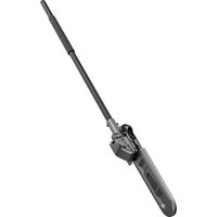
Black metal tool with a curved handle and flange, isolated on white background (no text or symbols)| Curved Edger attachment | EN | P02 |
| Gebogener Kantenschneideraufsatz | D | P13 |
| Accessoire de coupe-bordure incurvé | F | P25 |
| Accessorio per tagliabordi curvo | I | P36 |
| Accesorio de cortamárgenes curvo | ES | P47 |
| Acessório de corte curvo | PT | P58 |
| Gebogen kantensnijderopzetstuk | NL | P69 |
| Íves szegélynyíró tartozék | HU | P80 |
| Accesoriu pentru margini curbe | RO | P91 |
| Przystawka obrzynarki zakrzywionej | PL | P102 |
| Nástavec se zahnutými nůžkami na okraje trávníku | CZ | P113 |
| Nástavec orezávača so zakriveným hriadel'om | SK | P124 |
| Priključek prirezovalnik za ukrivljene robove | SL | P135 |
| Nastavak zakrivljenog rezača rubova travnjaka | HR | P146 |
| Kantskærerpåsats med buet skaft | DK | P156 |
| Kaareva reunaleikkuri | FIN | P166 |
| Utstyr for buet kantklipper | NOR | P176 |
| Krökt kantskärartillbehör | SV | P186 |
KAC142
TABLE OF CONTENTS
Introduction....3
Component List....3
Product Safety....4
Assembly&Operation....7
Transportation....8
Maintenance....8
Cleaning....9
Storage....9
Troubleshooting....9
Technical Data....10
EN
Environmental Protection....11
Declaration of Conformity....11
INTRODUCTION
Dear Customer,
Thank you for buying this Kress Commercial product. We are dedicated to developing high quality products to meet your commercial landscaping requirements.
The Kress brand is synonymous with premium quality service. Over the years of your product's life, if you have any questions or concerns about your product, please contact your dealer or our Customer Service Team for assistance.
We are confident you will enjoy working with your Kress product for years to come.
INTENDED USE
In conjunction with KAC104 - Power Head, this machine is intended for edging along sidewalks, driveways, curbs and patios.
EN
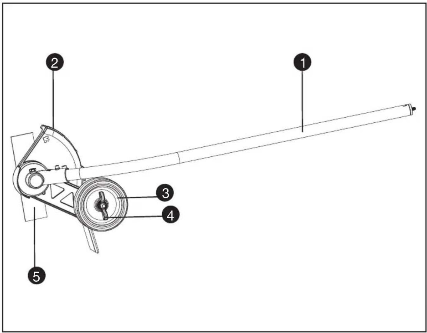
COMPONENT LIST
- SHAFT
- DEBRIS GUARD
- SUPPORT WHEEL
- SUPPORT WHEEL ADJUSTMENT WING NUT
- BLADE
ORIGINAL INSTRUCTION PRODUCT SAFETY GENERAL OUTDOOR POWER EQUIPMENT SAFETY WARNINGS
WARNING: Read all safety warnings, instructions, illustrations and specifications provided with this outdoor power equipment.
Failure to follow all instructions listed below may result in electric shock, fire and/or serious injury.
Save all warnings and instructions for future reference.
The term "outdoor power equipment" in the warnings refers to your mains-operated (corded) outdoor power equipment or battery-operated (cordless) outdoor power equipment.
1. Work area safety
a) Keep work area clean and well lit. Cluttered or dark areas invite accidents.
b) Do not operate outdoor power equipments in explosive atmospheres, such as in the presence of flammable liquids, gases or dust. Outdoor power equipments create sparks which may ignite the dust or fumes.
c) Keep children and bystanders away while operating a outdoor power equipment. Distractions can cause you to lose control.
2. Electrical safety
a) Outdoor power equipment plugs must match the outlet. Never modify the plug in any way. Do not use any adapter plugs with earthed (grounded) outdoor power equipments. Unmodified plugs and matching outlets will reduce risk of electric shock.
b) Avoid body contact with earthed or grounded surfaces, such as pipes, radiators, ranges and refrigerators. There is an increased risk of electric shock if your body is earthed or grounded.
c) Do not expose power tools to rain or wet conditions. Water entering a power tool will increase the risk of electric shock. Do not operate the machine in rain or wet conditions. This may increase the risk of electric shock.
d) Do not abuse the cord. Never use the cord for carrying, pulling or unplugging the outdoor power equipment. Keep cord away from heat, oil, sharp edges or moving parts. Damaged or entangled cords increase the risk of electric shock.
e) When operating a outdoor power equipment outdoors, use an extension cord suitable for outdoor use. Use of a cord suitable for outdoor use reduces the risk of electric shock.
f) If operating a outdoor power equipment in a damp location is unavoidable, use a residual current device (RCD) protected supply. Use of
an RCD reduces the risk of electric shock.
3. Personal safety
a) Stay alert, watch what you are doing and use common sense when operating a outdoor power equipment. Do not use a outdoor power equipment while you are tired or under the influence of drugs, alcohol or medication. A moment of inattention while operating outdoor power equipments may result in serious personal injury.
b) Use personal protective equipment. Always wear eye protection. Protective equipment such as dust mask, non-skid safety shoes, hard hat, or hearing protection used for appropriate conditions will reduce personal injuries.
c) Prevent unintentional starting. Ensure the switch is in the off-position before connecting to power source and/or battery pack, picking up or carrying the tool. Carrying outdoor power equipments with your finger on the switch or energising outdoor power equipments that have the switch on invites accidents.
d) Remove any adjusting key or wrench before turning the outdoor power equipment on. A wrench or a key left attached to a rotating part of the outdoor power equipment may result in personal injury.
e) Do not overreach. Keep proper footing and balance at all times. This enables better control of the outdoor power equipment in unexpected situations.
f) Dress properly. Do not wear loose clothing or jewellery. Keep your hair, clothing and gloves away from moving parts. Loose clothes, jewellery or long hair can be caught in moving parts.
g) If devices are provided for the connection of dust extraction and collection facilities, ensure these are connected and properly used. Use of dust collection can reduce dust-related hazards.
h) Do not let familiarity gained from frequent use of tools allow you to become complacent and ignore tool safety principles. A careless action can cause severe injury within a fraction of a second.
4. Outdoor Power Equipment use and care
a) Do not force the outdoor power equipment. Use the correct outdoor power equipment for your application. The correct outdoor power equipment will do the job better and safer at the rate for which it was designed.
b) Do not use the outdoor power equipment if the switch does not turn it on and off. Any outdoor power equipment that cannot be controlled with the switch is dangerous and must be repaired.
c) Disconnect the plug from the power source and/or remove the battery pack, if detachable, from the power tool before making any adjustments, changing accessories, or storing outdoor power equipments. Such preventive
safety measures reduce the risk of starting the outdoor power equipment accidentally.
d) Store idle outdoor power equipments out of the reach of children and do not allow persons unfamiliar with the outdoor power equipment or these instructions to operate the outdoor power equipment. Outdoor power equipments are dangerous in the hands of untrained users.
e) Maintain outdoor power equipment and accessories. Check for misalignment or binding of moving parts, breakage of parts and any other condition that may affect the outdoor power equipment's operation. If damaged, have the outdoor power equipment repaired before use. Many accidents are caused by poorly maintained outdoor power equipments.
f) Keep cutting tools sharp and clean. Properly maintained cutting tools with sharp cutting edges are less likely to bind and are easier to control.
g) Use the outdoor power equipment, accessories and tool bits etc. in accordance with these instructions, taking into account the working conditions and the work to be performed. Use of the outdoor power equipment for operations different from those intended could result in a hazardous situation.
h) Keep handles and grasping surfaces dry, clean and free from oil and grease. Slippery handles and grasping surfaces do not allow for safe handling and control of the tool in unexpected situations.
5. Battery tool use and care
a) Recharge only with the charger specified by the manufacturer. A charger that is suitable for one type of battery pack may create a risk of fire when used with another battery pack.
b) Use outdoor power equipments only with specifically designated battery packs. Use of any other battery packs may create a risk of injury and fire.
c) When battery pack is not in use, keep it away from other metal objects, like paper clips, coins, keys, nails, screws or other small metal objects, that can make a connection from one terminal to another. Shorting the battery terminals together may cause burns or a fire.
d) Under abusive conditions, liquid may be ejected from the battery; avoid contact. If contact accidentally occurs, flush with water. If liquid contacts eyes, additionally seek medical help. Liquid ejected from the battery may cause irritation or burns.
e) Do not use a battery pack or tool that is damaged or modified. Damaged or modified batteries may exhibit unpredictable behaviour resulting in fire, explosion or risk of injury.
f) Do not expose a battery pack or tool to fire or excessive temperature. Exposure to fire or temperature above 130 °C may cause explosion.
g) Follow all charging instructions and do not charge the battery pack or tool outside the temperature range specified in the instructions. Charging improperly or at
temperatures outside the specified range may damage the battery and increase the risk of fire.
6. Service
a) Have your outdoor power equipment serviced by a qualified repair person using only identical replacement parts. This will ensure that the safety of the outdoor power equipment is maintained.
b) Never service damaged battery packs. Service of battery packs should only be performed by the manufacturer or authorized service providers.
SAFETY INSTRUCTIONS FOR EDGERS
1. Training
a) Read the instructions carefully. Be familiar with the controls and the proper use of the equipment.
b) Never allow children or people unfamiliar with these instructions to use the edger. Local regulations may restrict the age of the operator.
c) Never edge while people, especially children, or pets are nearby.
d) Keep in mind that the operator or user is responsible for accidents or hazards occurring to other people or their property.
2. Preparation
a) While edging, always wear eye and ear protection, substantial foot wear, and long trousers.
b) Thoroughly inspect the surface where the equipment is to be used and remove all stones, sticks, wires, bones and other foreign objects.
c) Before using, always visually inspect to see that the blades, blade bolts and cutter assembly are not worn or damaged. Replace worn or damaged blades and bolts in sets to preserve balance.
d) Use only manufacturer-recommended replacement parts and accessories.
3. Operation
a) Edge only in daylight or in good artificial light.
b) Always be sure of your footing on slopes.
c) Walk, never run.
d) Use extreme caution when reversing or pulling the edger toward you.
e) Make sure the blade has stopped before crossing surfaces other than grass and when transporting the edger to and from the area to be edged.
f) Never operate the edger with defective, missing or incorrectly fitted guards.
g) Switch on the motor carefully according to instructions and with feet well away from the blade(s).
h) Do not tilt when switching on the motor, unless the edger has to be tilted for starting. In this case, do not tilt it more than absolutely necessary and lift only the part which is away
from the operator.
i) Do not switch on the motor when a bystander is standing in front of the blade(s).
j) Do not put hands or feet near or under rotating parts.
k) Always switch off the electric motor and remove battery pack from the machine:
1) before clearing blockages;
2) before checking, cleaning or working on the blade(s);
3) after striking a foreign object: inspect the blade(s) for damage and make repairs before restarting and operating the edger;
4) if edger starts to vibrate abnormally (check immediately).
I) Always remove battery pack from the machine whenever you leave the edger.
m) Always ensure that the ventilation openings are kept clear of debris.
4. Maintenance and storage
a) Keep all nuts, bolts and screws tight to be sure the equipment is in safe working conditions.
b) Replace worn or damaged parts.
c) Do not attempt to repair the machine unless you are competent to do so.
d) Use only manufacturer-recommended replacement parts and accessories.
e) When not in use, store the edger out of the reach of children.
f) Inspect and maintain the edger regularly.
Have the edger repaired only by an authorized repairer.
SAFETY WARNINGS FOR BATTERY PACK
a) Do not dismantle, open or shred cells or battery pack.
b) Do not short-circuit a battery pack. Do not store battery packs haphazardly in a box or drawer where they may short-circuit each other or be short-circuited by conductive materials. When battery pack is not in use, keep it away from other metal objects, like paper clips, coins, keys, nails, screws or other small metal objects, that can make a connection from one terminal to another. Shorting the battery terminals together may cause burns or a fire.
c) Do not expose battery pack to heat or fire. Avoid storage in direct sunlight.
d) Do not subject battery pack to mechanical shock.
e) In the event of battery leaking, do not allow the liquid to come into contact with the skin or eyes. If contact has been made, wash the affected area with copious amounts of water and seek medical advice.
f) Keep battery pack clean and dry.
g) Wipe the battery pack terminals with a clean dry cloth if they become dirty.
h) Battery pack needs to be charged before use. Always refer to this instruction and use the
correct charging procedure.
i) Do not maintain battery pack on charge when not in use.
j) After extended periods of storage, it may be necessary to charge and discharge the battery pack several times to obtain maximum performance.
k) Recharge only with the charger specified by Kress. Do not use any charger other than that specifically provided for use with the equipment.
I) Do not use any battery pack which is not designed for use with the equipment.
m) Keep battery pack out of the reach of children.
n) Retain the original product literature for future reference.
o) Remove the battery from the equipment when not in use.
p) Dispose of properly.
q) Do not use battery packs of different manufacture, size or type.
r) Keep the battery away from microwaves and high pressure.
s) Warning! Do not use non-rechargeable batteries.
SAVE THESE INSTRUCTIONS
SYMBOLS
 | To reduce the risk of injury,user must read instructionmanual |
 | WARNING |
 | Wear ear and eye protection |
 | Direction of edger bladerotation |
 | Keep bystanders at a safedistance |
 | Thrown objects |
 | Rotating cutting blade |
 | Waste electrical products must not be disposed of with household waste. Please recycle where facilities exist. Check with your local authorities or retailer for recycling advice. |
 Li-Ion Li-Ion | Li-Ion battery This product has been marked with a symbol relating to 'separate collection' for all battery packs and battery pack. It will then be recycled or dismantled in order to reduce the impact on the environment. Battery packs can be hazardous for the environment and for human health since they contain hazardous substances. |
 | Do not burn |
 | Batteries may enter water cycle if disposed improperly, which can be hazardous for ecosystem. Do not dispose of waste batteries as unsorted municipal waste. |
 | Wear protective gloves |
 | Remove battery from the socket before carrying out any adjustment, servicing or maintenance. |
NOTE: Before using the tool, read the instruction book carefully.

BEFORE OPERATION:
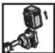
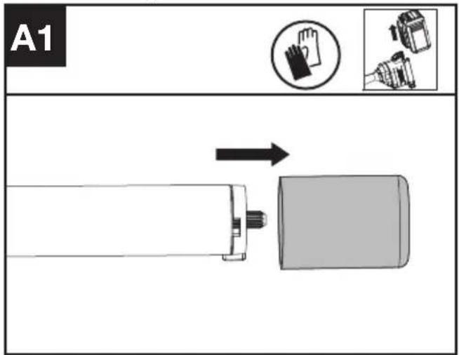
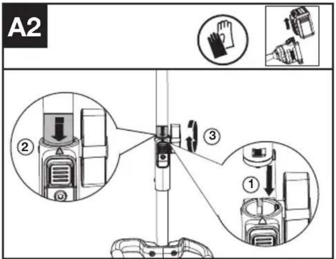
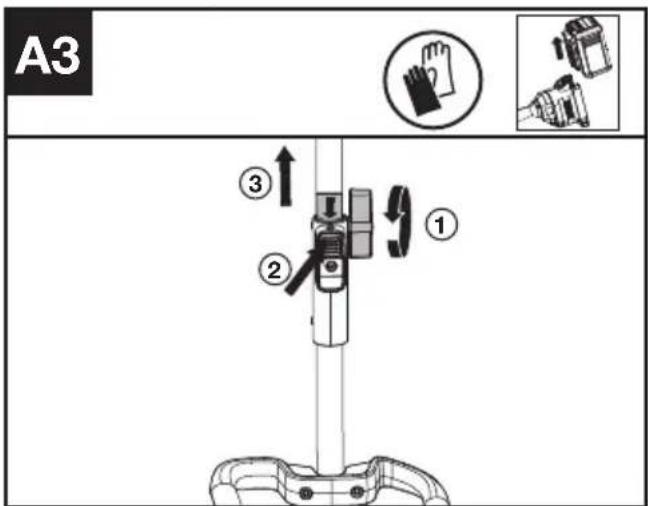
Assembling and disassembling the Power head attachment. (See Fig. A1, A2, A3)
- Remove the protective cap from the end of the attachment shaft.
- To assemble, align the triangle icon on the button with the arrow label on the attachment shaft.
- Push the shafts together until you hear a "click". The edge of the arrow label should be close to the shaft connection housing.(Note: If the curved edger working head cannot be fully installed into the power head, rotate the blade a little until it is
possible to insert the shaft fully.)
- Finish the assembly by tightening the knob clockwise.
- To disassemble, loosen the knob, turn counter clockwise, then press the release button and pull the shafts apart. Replace the protective cap on the attachment shaft to ensure that dust and debris do not get into the shaft.
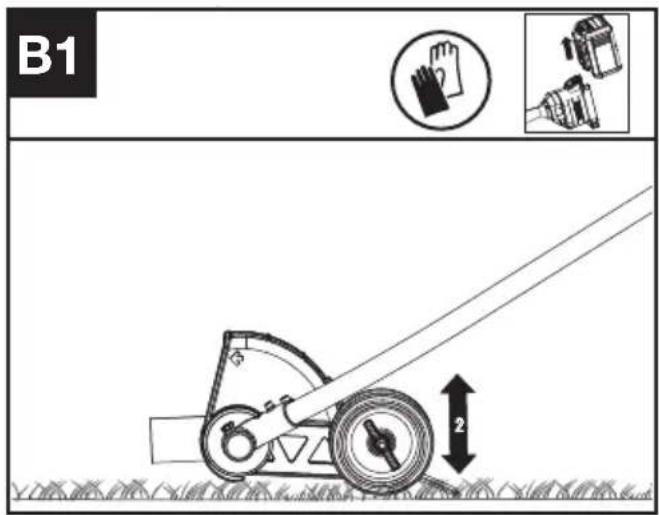
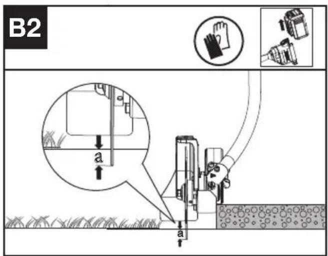
Adjust the cutting height (See Fig. B1, B2)
- Turn off the power tool and remove the battery.
-
Loosen the wing nut. Push the wheel upwards to increase the cut depth (a) or downward the wheel to reduce the cut depth (a).
-
It is recommended to adjust the depth wheel so that the edger blade just touching the ground or breaks the surface of the soil by no more than 0.2 in. (5 mm)
- Tighten the wing nut. Check the depth of cut while standing in the normal working position and correct it if necessary.
OPERATION: Starting the edger (See Fig. C)
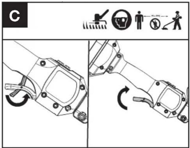
- Push the Safety Lock Off Lever forward first, then squeeze and hold the throttle trigger to start the machine
NOTE: More details can be found in the power head manual.
TRANSPORTATION
Transporting the edger
- Switch off the edger and remove the battery.
- When transporting your edger by hand, hold the middle of shaft to make sure that your machine is parallel to the ground.
- When transporting your edger in a vehicle, secure and position it to prevent movement or damage.
For Battery tools
The recommended ambient temperature range for discharging is -4^ 113^ (-20°C\~45°C).
The recommended ambient temperature range for the charging system during charging is 23^ F\~ 113^ F (-5°C\~45°C).
MAINTENENCE
Replacing the blade (See Fig. D1, D2, D3)
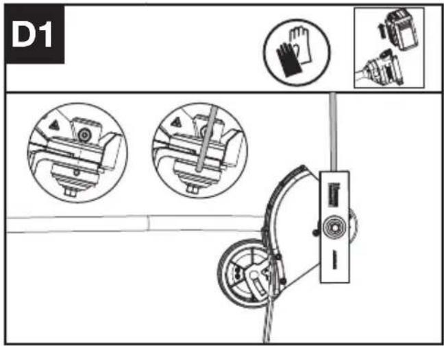
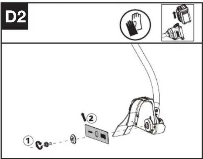
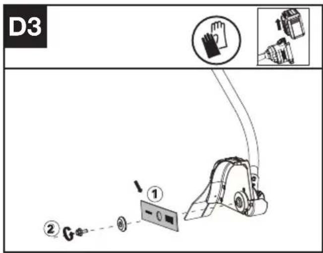
- Align hole in inner blade adapter with notch in gear housing, and insert locking tool to prevent from rotating.
- Loosen the bolt.
- Replace the blade and tighten the bolt to 15\~20 Nm (11\~15 ft-lb).
Lubricating the Gear Box (See Fig. E1, E2)
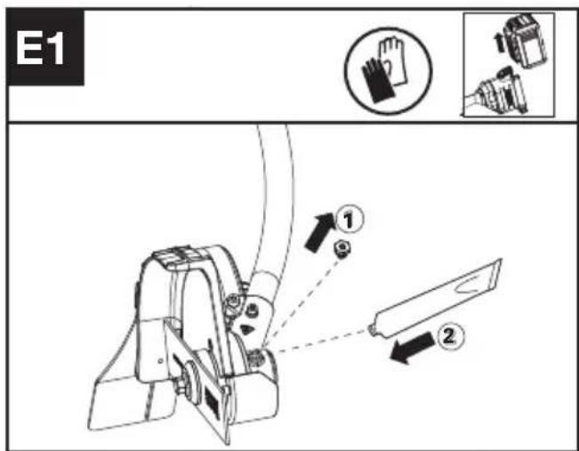
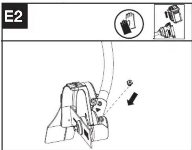
- Remove the screw plug from the gear housing and inject about 5g of grease into gear case every time.
- Tighten the screw.
NOTE: Lubricating the gear case through the oil-hole after every 50 hours operation. For best operation and longer lifetime, it is recommended to lubricate the Lawn Edger gear case with dedicated grease (SHELL Gadus S2 V220 1).
CLEANING
- Switch off the edger and remove the battery.
- Do not use aggressive detergents or solvents. Clean the machine after use with a damp cloth dipped in mild detergent.
- Keep battery connection free of dirt and debris, and clean with a soft and dry brush or cloth.
- Do not spray water onto the motor and electrical components.
- Do not use pressure washer to clean your machine.
STORAGE
- Remove the battery pack from the edger before storage.
- Store the edger and the battery in a dry and secure place that is inaccessible to children and other unauthorized people. Remove the cutting attachment if no use for a long time.
- If the machine becomes wet in the rain during operation, the machine and the battery should be dried before storing or charging. Remove the battery and reinsert it if the machine fails to turn on.
TROUBLESHOOTING
The following table gives problems and actions that you can perform if your machine does not operate correctly.
WARNING: Switch the machine off and remove the battery prior to any troubleshooting.
EDGER
| Problems Possible Causes | Corrective Action | |
| Battery indicator LED flashing | Low battery voltage. | Charge the battery. |
| Error LED flashing | Overload. The cutting attachment is jammed. Deactivate the product. Remove the battery. Clean the cutting attachment from unwanted materials. | |
| Temperature issue. | Let the product cool down. | |
| The Throttle Trigger and the start/stop button are pressed at the same time. | Release Throttle Trigger. Perform the starting sequence again. | |
| Other problems | Contact Service Agent | |
| The product does not start | Debris in the battery connectors. | Clean the battery connectors with compressed air or a soft brush. |
| The power of the battery pack has been run out. | Charge the battery pack. | |
| Other problems | Contact Service Agent. | |
| Edger runs intermittently | The battery is not fully inserted to the machine. | Remove & reinsert battery fully. |
| Potential electrical issue. | Contact Service Agent. | |
| Excessive vibrations/ noise. | Blade balance issue. | Evaluate blade for damage, replace blade. |
| Soil/debris build-up in blade guard. | Clean blade guard, remove debris. | |
| Cutting attachment issue. Machine defective. | Replace cutting attachment. Contact Service Agent. | |
TECHNICAL DATA
| KAC142 | |
| Cutting Speed | 5400/7000rpm |
| Blade Size | 20 cm |
| Degree of protection | IPX4 |
| Machine Weight (Bare tool) | 2.3 kg |
COMBINATIONS OF CUTTING ATTACHMENTS AND CARRYING SYSTEMS
| Cutting attachment Carrying system | |
| 20 cm replacement edger blade | - Shoulder strap- Backpack batteryHarness |
NOISE INFORMATION
| A weighted sound pressure L | _pA =77.1 dB(A) |
| K_pA | 3 dB(A) |
| A weighted sound power L | _wA =93.68 dB(A) |
| K_wA | 1.37 dB(A) |
| Wear ear protection |
VIBRATION INFORMATION
| Vibration total values (triax vector sum) determined according to EN 62841: | |
| Typical weighted vibration | a _h < 2,1 m/s^2 |
| Uncertainty K < 1,5 m/s ^2 | |
The declared vibration total value and the declared noise emission value have been measured in accordance with a standard test method and may be used for comparing one tool with another.
The declared vibration total value and the declared noise emission value may also be used in a preliminary assessment of exposure.

WARNING: The vibration and noise emissions during actual use of the power tool can differ
from the declared value depending on the ways in which the tool is used especially what kind of workpiece is processed dependant on the following examples and other variations on how the tool is used:
How the tool is used and the materials being cut or drilled.
The tool being in good condition and well maintained.
The use of the correct accessory for the tool and ensuring it is sharp and in good condition.
The tightness of the grip on the handles and if any anti vibration and noise accessories are used. And the tool is being used as intended by its design and these instructions.
This tool may cause hand-arm vibration syndrome if its use is not adequately managed.

WARNING: To be accurate, an estimation of exposure level in the actual conditions of use should also take account of all parts of the operating cycle such as the times when the tool is switched off and when it is running idle but not actually doing the job. This may significantly reduce the exposure level over the total working period.
Helping to minimise your vibration and noise exposure risk.
Always use sharp chisels, drills and blades.
Maintain this tool in accordance with these instructions and keep well lubricated (where appropriate).
If the tool is to be used regularly then invest in anti-vibration and noise accessories.
Plan your work schedule to spread any high vibration tool use across a number of days
ENVIRONMENTAL PROTECTION

Waste electrical products must not be disposed of with household waste. Please
recycle where facilities exist. Check with your local authorities or retailer for recycling advice.
DECLARATION OF CONFORMITY
We,
Positec Germany GmbH
Postfach 680194, 50704 Cologne, Germany
On behalf of Positec declare that the product, Description Battery operated lawn edger Type KAC142 (142-designation of machinery, representative of Battery operated lawn edger) Function trimming grass edger
Complies with the following Directives:
2006/42/EC, 2014/30/EU, 2011/65/
EU&(EU)2015/863, 2000/14/EC amended by 2005/88/EC
2000/14/EC amended by 2005/88/EC:
- Conformity Assessment Procedure as per Annex V
- Measured Sound Power Level 94 dB (A)
- Declared Guaranteed Sound Power Level 96 dB (A)
Standards conform to,
EN 62841-1, ISO 11789, EN ISO 3744,
EN IEC 55014-1, EN IEC 55014-2, EN IEC 63000
The person authorized to compile the technical file, Name Marcel Filz
Address Positec Germany GmbH
Postfach 680194, 50704 Cologne, Germany


2024/3/8
Allen Ding
Deputy Chief Engineer Testing & Certification
Positec Technology (China) Co., Ltd
18, Dongwang Road, Suzhou Industrial
Park, Jiangsu 215123, P. R. China
DECLARATION OF CONFORMITY
We,
Positec (UK & Ireland) Ltd
PO Box 6242, Newbury, RG14 9LT, UK
On behalf of Positec declare that the product,
Description Battery operated lawn edger
Type KAC142 (142-designation of machinery, representative of Battery operated lawn edger)
Function trimming grass edger
Complies with the following regulations:
Supply of Machinery (Safety) Regulations 2008
Electromagnetic Compatibility Regulations 2016
The Restriction of the Use of Certain Hazardous
Substances in Electrical and Electronic
Equipment Regulations
Noise Emission in the Environment by Equipment for Use Outdoors Regulations
- Conformity Assessment Procedure as per
SCHEDULE 8
- Measured Sound Power Level 94 dB (A)
- Declared Guaranteed Sound Power Level 96 dB (A)
Standards conform to,
BS EN 62841-1, ISO 11789, BS EN ISO 3744, BS
EN IEC 55014-1, BS EN IEC 55014-2, BS EN IEC 63000
The person authorized to compile the technical file,
Name Jim Kirkwood
Address Positec (UK & Ireland) Ltd,
PO Box 6242, Newbury, RG14 9LT, UK


2024/3/8
Allen Ding
Deputy Chief Engineer Testing & Certification
Positec Technology (China) Co., Ltd
18, Dongwang Road, Suzhou Industrial
Park, Jiangsu 215123, P. R. China
INHALTSVERZEICHNIS
Einführung....13
Komponenten....14
KOMPONENTEN
18, Dongwang Road, Suzhou Industrial
Park, Jiangsu 215123, P. R. China
SOMMAIRE
Introduction......25
LISTE DES COMPOSANTS
- FLASQUE
- PROTECTION ANTI-DÉBRIS
- ROUE DE SOUTIEN
- ÉCROU À AILETTES DE RÉGLAGE DE LA ROUE DE SOUTIEN
- LAME
NOTICE ORIGINALE AVERTISSEMENTS DE SÉCURITÉ SÉCURITÉ DU PRODUIT AVERTISSEMENTS GÉNÉRAUX DE SÉCURITÉ POUR L'OUTIL

INFORMATIONS RELATIVES AU BRUIT
INFORMATIONS RELATIVES AUX VIBRATIONS
DÉCLARATION DE CONFORMITÉ
Nous, Positec Germany GmbH Postfach 680194, 50704 Cologne, Germany
ELENCO COMPONENTI
- ALBERO
- PROTEZIONE ANTI-DETRITI
- RUOTA DI SUPPORTO
- DADO A FARFALLA PER LA REGOLAZIONE DELLA RUOTA DI SUPPORTO
- LAMA
ISTRUZIONI ORIGINALI AVVISI PER LA SICUREZZAGENERALI PER LA SICUREZZA DEGLI UTENSILI A MOTORE

18, Dongwang Road, Suzhou Industrial
Park, Jiangsu 215123, P. R. China
TUTELA AMBIENTALE

18, Dongwang Road, Suzhou Industrial
Park, Jiangsu 215123, P. R. China
ÍNDICE
Introdução....58
Lista de componentes....59
PT
18, Dongwang Road, Suzhou Industrial
Park, Jiangsu 215123, P. R. China
INHOUDSOPGAVE
Inleiding....69
ONDERDELENLIJST
WAARSCHUWING: Voor de
18, Dongwang Road, Suzhou Industrial
Park, Jiangsu 215123, P. R. China
TARTALOMJEGYZÉK
Bevezető....80
HU
18, Dongwang Road, Suzhou Industrial
Park, Jiangsu 215123, P. R. China
KÖRNYEZETVÉDELEM

LISTA DE COMPONENTE
- ARBORE
- PROTECTIEI ÎMPOTRIVA RESTURILOR
- ROATĂ DE SUPORT
- PIULITĂ-FLUTURE PENTRU REGLAREA ROȚII DE SUPORT
- LAMÄ
INSTRUCTIUNI ORIGINALE SECURITATEA PRODUSULUI AVERTISMENTE GENERALE DE SIGURANTĂ PENTRU UNELTE ELECTRICE
18, Dongwang Road, Suzhou Industrial
Park, Jiangsu 215123, P. R. China
SPIS TREŚCI
Wprowadzenie....102
PL
LISTA KOMPONENTÓW
18, Dongwang Road, Suzhou Industrial
Park, Jiangsu 215123, P. R. China
OBSAH
Úvod....113
SEZNAM KOMPONENTÜ
- RUKOJETI
- OCHRANNÉHO KRYTU PROTI NEČISTOTÁM
- OPĚRNÉ KOLO
- KŘÍDLOVÁ MATICE PRO SEŘÍZENÍ OPĚRNÉHO KOLA
- ČEPEL
PŮVODNÍ NÁVOD K POUŽÍVÁNÍ BEZPEČNOST VÝROBKU OBECNÁ BEZPEČNOSTNÍ UPOZORNĚNÍ PRO ELEKTRICKÉ NÁSTROJE

TYTO POKYNY USCHOVEJTE
SYMBOLY

INFORMACE TÝKAJÍCÍ SE HLUČNOSTI
18, Dongwang Road, Suzhou Industrial
Park, Jiangsu 215123, P. R. ChinaPositec
Technology (China) Co., Ltd
18, Dongwang Road, Suzhou Industrial
Park, Jiangsu 215123, P. R. China
OBSAH
Úvod....124
SK
ZOZNAM SÚČASTÍ
- TYČ
- OCHRANNÉHO KRYTU PROTI ÚLOMKOM
- OPORNÉ KOLESO
- KRÍDLOVÁ MATICA NASTAVENIA PODPORNÉHO KOLESA
- ČEPEL'
PÔVODNÝ NÁVOD NA POUŽITIE BEZPEČNOST VÝROBKU VŠEOBECNÉ BEZPEČNOSTNÉ UPOZORNENIA

TIETO POKYNY USCHOVAJTE
SYMBOLY
- Zarovnajte otvor vo vnútornom adaptéri čepele so zárezom v kryte prevodovky a vložte uzamykací nástroj, aby ste zabránili otáčaniu.
- Uvol'nite skrutku.
- Vymeňte nôž a utiahnite skrutku na 15-20 Nm (11-15 ft-lb).
18, Dongwang Road, Suzhou Industrial
Park, Jiangsu 215123, P. R. China
KAZALO VSEBINE
Uvod....135
Sestavni deli....136
Varnost izdelka....137
Sestavljanje in delovanje....140
Prevoz....142
Vzdrževanje....142
Čiščenje....143
Shranjevanje....143
SESTAVNI DELI
- GREDI
- ŠČITNIKA ZA OBREZKE
- OPORNO KOLO
- NASTAVNA KRILATA MATICA OPORNEGA KOLESA
- REZILO
IZVIRNA NAVODILA VARNOST IZDELKA SPLOŠNA VARNOSTNA OPOZORILA

- Poravnajte luknjo v adapterju notranjega rezila z zarezo v ohišju prestave in vstavite orodje za zaklepanje (ni priloženo), da preprečite vrtenje.
- Odvijte vijak.
- Zamenjajte rezilo in privijte vijak na 15\~20 Nm (11\~15 ft-lb).
HR
POPIS KOMPONENTI
- OSOVINA
- ŠTITNIK OD KRHOTINA
- POTPORNI KOTAČ
- LEPTIRASTA MATICA ZA PRILAGOĐAVANJE POTPORNOG KOTAČA
- OŠTRICA
ORIGINALNE UPUTE ZA RAD SIGURNOST PROIZVODA UOBICAJENA SIGURNOSNA UPOZORENJA ZA ELEKTRIČNE ALATE

UPOZORENJE Pročitajte sva sigurnosna upozorenja, upute, ilustracije i specifikacije
DK
18, Dongwang Road, Suzhou Industrial
Park, Jiangsu 215123, P. R. China
SISÄLLYSLUETTELO
Johdanto....166
Komponenttiluettelo....167
FIN
KOMPONENTTILUETTELO
- VARI SI
- ROSKASUOJA
- TUKIPYÖRÄ
- TUKIPYÖRÄN SÄÄTÖSIIPIMUTTERI
- TERÄ
ALKUPERÄISET OHJEET TURVALLISUUSOHJEET TUOTETURVALLISUUS YLEISET SÄHKÖTYÖKALUJEN TURVALLISUUTEEN LIITTYVÄT VAROITUKSET
NOR
KOMPONENTLISTE
- AKSEL
- BESKYTTELSESSKJERMEN
- ST∅TTEHJUL
- VINGEMUTTER FOR JUSTERING AV ST∅TTEHJUL
- BLAD
ORIGINAL DRIFTSINSTRUKS PRODUKTSIKKERHET GENERELLE ADVARSLER FOR ELEKTROVERKT∅Y

ADVARSEL Les alle
18, Dongwang Road, Suzhou Industrial
Park, Jiangsu 215123, P. R. China
INNEHÅLLSFÖRTECKNING
Introduktion....186
Komponenter....187
Produktsäkerhet.... 188
SV
KOMPONENTER
- SKAFT
- SKRÄPSKYDD
- STÖDHJUL
- VINGMUTTER FÖR JUSTERING AV STÖDHJUL
- KNIV
ORIGINAL DRIFTSINSTRUKS PRODUKTSIKKERHET GENERELLE ADVARSLER FOR ELEKTROVERKT∅Y

ADVARSEL Les alle
18, Dongwang Road, Suzhou Industrial
Park, Jiangsu 215123, P. R. China

Copyright © 2024, Positec. All Rights Reserved.
AR01757700