Cine 1 - Projector LEICA - Free user manual and instructions
Find the device manual for free Cine 1 LEICA in PDF.

| Product type | Laser TV projection screen |
| Brand | Leica |
| Model | Cine 1 |
| Screen size | 120 inches (diagonal) |
| Projection area | 2657 × 1494 mm |
| Aspect ratio | 16:9 |
| Screen material | PET + PU |
| Horizontal viewing angle | ≥ 70° |
| Screen color | Black |
| Frame color | Black |
| Product dimensions (W × H × D) | 2697 × 1534 × 31 mm |
| Package dimensions | 1700 × 492 × 317 mm |
| Product weight | 15.1 kg |
| Accessories included | Inner and outer frames, protective cloth, gloves, spring hooks, wall brackets, adjustment rods, dowels, paper template, Velcro strips |
| Installation type | Wall mounting (not recommended for ceiling) |
| Recommended number of people for installation | 2 |
| Care and cleaning | Soft cotton cloth, horizontal wiping only, avoid organic solvents |
| Safety instructions | Do not look directly at the laser; installation by qualified person; keep out of reach of children |
| Warranty | Leica additional product warranty (conditions online) |
| Customer service | Leica Customer Care: +49 6441 2080-189, customer.care@leica-camera.com |
Frequently Asked Questions - Cine 1 LEICA
User questions about Cine 1 LEICA
0 question about this device. Answer the ones you know or ask your own.
Ask a new question about this device
Download the instructions for your Projector in PDF format for free! Find your manual Cine 1 - LEICA and take your electronic device back in hand. On this page are published all the documents necessary for the use of your device. Cine 1 by LEICA.
USER MANUAL Cine 1 LEICA
BEKNOPTE HANDLEIDING
GUIDA RAPIDA
INSTRUCCIONES ABREVIADAS
КРАТКАЯ ИНСТРУКЦИЯ
VORWORT
Hinweis
flowchart
graph TD
    A["Rectangle with corners A1, A2, B, C"] -->|→| B["Rectangle with arrow down"]
    B --> C["Rectangle with arrow left"]
LEINWAND MONTIEREN
Hinweis
natural_image
Line drawing of a hand performing a wrist massage or acupressure technique (no text or symbols present)Abbildung 1

natural_image
Pure technical diagram of a rectangular frame with internal vertical and horizontal lines, no text or symbols present.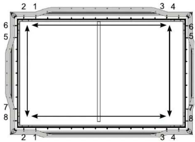

natural_image
Empty rectangular frame with a vertical line on the left side, surrounded by decorative border (no text or symbols)natural_image
Diagram showing a tool interacting with a panel-like structure, no text or symbols present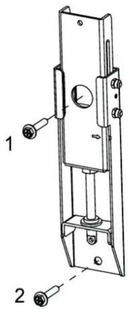
natural_image
Diagram showing a hammer striking a screw with a spring, illustrating the process (no text or symbols present)natural_image
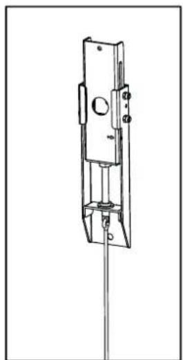
Technical line drawing of a mechanical lock or latch assembly (no text or symbols)LEINWAND AUFHÄNGEN
natural_image
Silhouette of two people holding a blank rectangular board (no text or symbols)natural_image
Pure architectural line drawing of a rectangular frame with vertical and horizontal lines, no text or symbols presentnatural_image
Simple circular diagram with a hanging ring and curved arrow, no text or symbols present.natural_image
Simple circular diagram with a hanging ring and curved arrow, no text or symbols present.natural_image
Pure technical line drawing of a rectangular frame with two vertical supports and two horizontal connectors, no text or symbols present.BEKNOPTE HANDLEIDING
GUIDA RAPIDA
INSTRUCCIONES ABREVIADAS
КРАТКАЯ ИНСТРУКЦИЯ
FOREWORD
Dear Customer,
We hope you enjoy using your new Leica Laser TV Screen for many years to come. Please begin by reading this manual thoroughly to familiarize yourself with the full scope of functions your screen has to offer.
Your Leica Camera AG
Please read the “Legal information”, “Safety information”, and “General information” sections before using the product for the first time to prevent product damage, injuries, and other risks.
Note
- If you have any questions or would prefer to have the screen professionally installed, please contact our Customer Care team (see the “Leica Customer Care” section).
LEGAL INFORMATION
TECHNICAL DATA
Changes to the product or services may have occurred after the editorial deadline. The manufacturer reserves the right to effect structural or shape changes, color variations, and changes to the scope of delivery or service during the delivery period where these are reasonably acceptable for the customer under consideration of the interests of Leica Camera AG. To that extent, Leica Camera AG reserves the right to changes and errors. The figures in this manual may depict accessories, special features, or other items that are not part of the standard scope of delivery or service. Some pages may present model types and services that are not offered in certain countries.
BRANDS AND LOGOS
The brands and logos used in this document are protected trademarks and must not be used without prior approval by Leica Camera AG.
SAFETY INFORMATION
GENERAL INFORMATION
- Do not commence installation until you have read the complete user manual and fully understood its content.
- This product should only be installed by persons with technical and mechanical knowledge.
- The safe installation of this product requires two people.
- It is important to ensure that screws are tightened sufficiently but without applying too much force. Excessive force may overtighten the screws, which can cause considerable damage.
- Do not use a cordless screwdriver or similar.
- This product is designed for indoor use only. Any outdoor use may result in irreparable damage.
- Suspended loads must be checked at least twice a year to ensure they are secure and offer sufficient load-bearing capacity.
OPERATING CONDITIONS AND USE
- The screen has a frame and is intended for use in rooms in which the ceiling lights cannot be moved.
- This screen must not be installed in the vicinity of radiators or air conditioning units, in locations exposed to direct sunlight, or directly in front of a window. The PVC surface of the projection screen fabric is temperature sensitive and can be damaged by exposure to extreme temperatures.
- We recommend waiting approx. 2 hours after delivery before installing the product, especially if the screen is moved from a cold to a warm environment. This allows the projection screen fabric to acclimatize.
- Please be very careful when handling the PVC projection screen fabric. Stains of any kind on the fabric must be avoided as they may be impossible to remove.
- It is also extremely important not to crease or touch the projection screen fabric as this can cause long-term damage.
GENERAL INFORMATION
- New products and materials may release chemicals into the air through evaporation. For the first few hours of operation, the device can therefore generate a slight odor. This is caused by some of the device components heating up for the first time. All materials used fully comply with environmental requirements and regulations. The vapors responsible for the odor will diminish over time. We recommend running the machine in a well-ventilated environment for some time before its actual initial use.
CARE AND STORAGE
- The surface of the screen has a horizontal structure. Do not wipe it from top to bottom or using circular movements; only wipe it from left to right.
- Never touch the screen with bare hands or wipe it with a regular towel.
- Do not spill dirty water, oil, or other contaminants on the screen.
- Never position the product on a cart, stand, or other piece of furniture that is unstable. The product falling to the ground could cause severe damage or personal injury.
- Never scratch or directly touch the front of the screen with hard objects.
- Do not expose the screen to direct sunlight.
- Do not position the screen in the immediate vicinity of flammable, explosive, or other hazardous products.
- Do not use any acetone, benzene, alcohol, or other organic solvents to clean the screen; these can permanently damage it.
MAINTENANCE AND REPAIR
- The screen can be gently wiped with a soft, lint-free, cotton cloth.
WARRANTY
In addition to your statutory warranty rights in relation to your retailer, you will receive an additional Leica Camera AG product warranty for this Leica product valid from the date of purchase from an authorized Leica retailer. The warranty conditions were previously included in the product packaging. As a new service, they are now only provided online. This offers the benefit that you can access the warranty conditions for your product at any time. Please note that this only applies to products that no longer come with a hard copy of the warranty conditions. In the case of products still delivered with a hard copy of the warranty conditions, these still exclusively apply. For more information regarding the warranty scope, warranty services, and limitations, please visit: https://warranty.leica-camera.com
LEICA CUSTOMER CARE
Please contact Leica Camera AG's Customer Care department for the maintenance of your Leica equipment or for help and advice regarding Leica products and how to order them. You can also contact the Customer Care department or the repair service provided by your regional Leica subsidiary for repairs or warranty claims.
LEICA GERMANY
Leica Camera AG
Leica Customer Care
Am Leitz-Park 5
35578 Wetzlar
Germany
Phone: +49(0)6441 2080-189
Fax: +49(0)6441 2080-339
E-mail: customer.care@leica-camera.com
https://leica-camera.com
YOUR NATIONAL REPRESENTATIVE
You will find the Customer Care department responsible for your locality on our website:
https://leica-camera.com/en-US/contact
SCOPE OF DELIVERY
Please check that you have received all the individual parts before commissioning your product. The standard scope of delivery* contains the following:
| Code | Name Part image | Quantity | |
| A1 | Inner frame long side 2 |  | |
| A2 | Inner frame long side 2 |  | |
| B | Inner frame short side 2 |  | |
| C | Corner connector for inner frame 4 |  | |
| D | Corner connector for inner frame 4 | 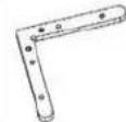 | |
| E | M4×6 screw 40 |  | |
| F | Protective sheet 1 |  | |
| G | Installation gloves 4 |  | |
| H | Screen 1 |  | |
| K | Spring hook 2 | 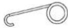 | |
| L1 | Outer frame long side 2 |  | |
| L2 | Outer frame long side 2 |  | |
| M | Outer frame short side 2 |  | |
| N | M3×7 screw 44 |  | |
| O | Vertical frame |  | 1 |
| P | Corner connector for outer frame | 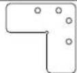 | 4 |
| Q | Longitudinal connector for inner framelong side |  | 2 |
| R | Longitudinal connector for inner framelong side |  | 2 |
| S | Longitudinal connector for outer framelong side |  | 2 |
| J | ST5.5x70 screw |  | 4 |
| Y | M3x6 screw 8 |  | |
| W | Wall bracket 2 |  | |
| X | Adjustment rod |  | 2 |
| Y1 | Adjustment rod for wall bracket 460 mm |  | 2 |
| Y2 | Adjustment rod for wall bracket 500 mm |  | 2 |
| Y3 | Adjustment rod for wall bracket 269 mm |  | 2 |
| Z1 | Wall plug 8x60 |  | 4 |
| Z2 | Paper template | 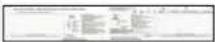 | 1 |
| Z3 | Velcro strips | [ST2K] | 4 |
* The actual scope of delivery may vary depending on the model.
Caution
- Desiccants and plastic bags must be stored out of the reach of children. Plastic bags pose a risk of suffocation and desiccants are a health hazard when swallowed.
ASSEMBLY
The following preparations must be made before commencing assembly.
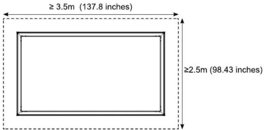
▶ Create sufficient space on a level and clean floor area. The assembly area should have a minimum size of 3.5 m x 2.5 m (137.8 inches x 98.43 inches).
▶ Lay the white protective sheet ( F ) flat on the ground
- Make sure that there are no foreign bodies on or under the protective sheet during assembly.
Note
- More than one of some of the components (e.g. the halves of the frame long sides, spacers, pressure plates) are provided. This can be seen in the figures. In such cases, the work steps described must be performed multiple times.
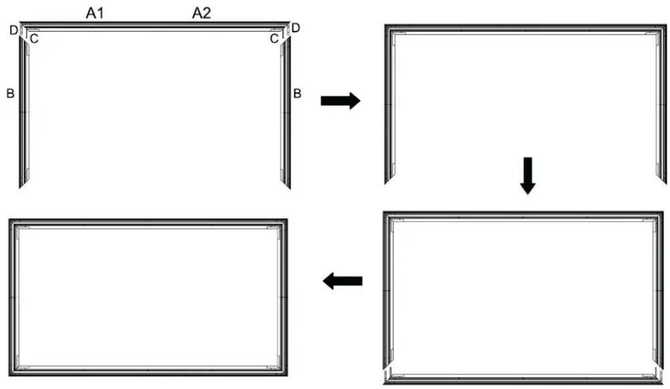
ASSEMBLING THE INNER FRAME
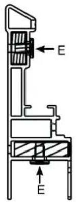
▶ Use the longitudinal connectors (Q and R) and the M4x6 screws (E) to connect the inner frame long sides (with 17 springs) (A1 and A2). Work in the following order:
- Use the M4x6 screws (E) to connect the longitudinal connectors (Q) and R to the inner frame long side (A1).
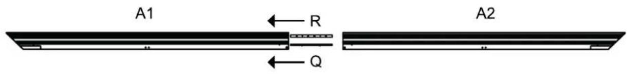
- Insert the longitudinal connectors (Q and R) into the inner frame long side (A2).
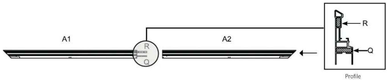
- Use the M4x6 screws (E) to connect the longitudinal connectors (Q) and R to the inner frame long side (A2).

- Insert the corner connector for the inner frame (C) followed by the corner connector for the inner frame (D) (with the front up) into each end of the inner frame long sides (A1 and A2) as shown below.
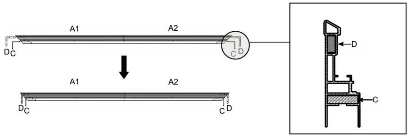
- Insert both inner frame short sides (B) into the corner connectors (C and D) as shown in the figure below.
flowchart
graph TD
    A["Rectangle with corners A1, A2, B, C"] -->|→| B["Rectangle with arrow down"]
    B --> C["Rectangle with arrow left"]
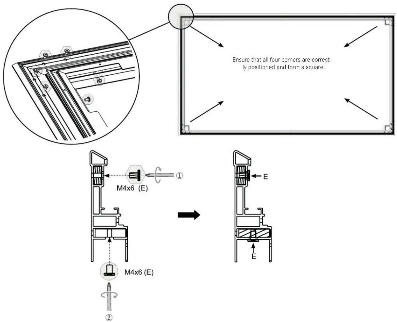
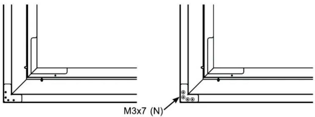
- Secure the four corners with the M4x6 screws (3). Start by tightening the screws marked with the symbol followed by the screws marked with the symbol (see the figure below).
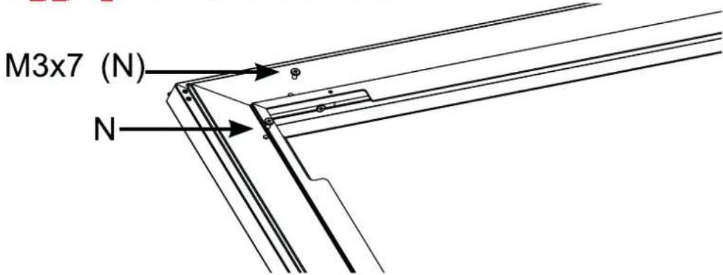
- Attach the vertical frame (O) to support the inner frame. Ensure that the vertical frame sits on the connection point of the inner frame long sides (A1 and A2) and is secured with four M3x7 screws (N).
MOUNTING THE SCREEN
Note
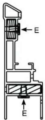
Before mounting the screen (H), put on the assembly gloves provided (E) to prevent the transfer of fingerprints, dust, or oil from your hands to the surface of the material (figure 1). The screen (H) is highly sensitive and should be handled with the utmost care. Ensure that the material is not misshapen or creased. Failure to observe the instructions can result in permanent damage to the screen material that is not covered by the warranty.
Remove the screen ( H ) from the packaging tube and carefully place it on a clean surface.
- Tip: carefully place a small, flat, heavy object on the edge to prevent the screen from slipping.
- Ensure the front of the screen points downward.
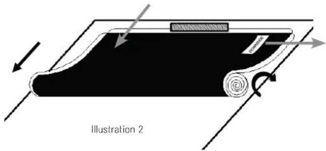
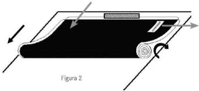
We strongly recommend the screen being unrolled by two people to prevent it from bending or unrolling unevenly.
• Each person should hold one end of the roll and slowly unroll the screen in a clockwise direction (figure 2).
- Tip: check the labeling to determine which is the underside of the screen.
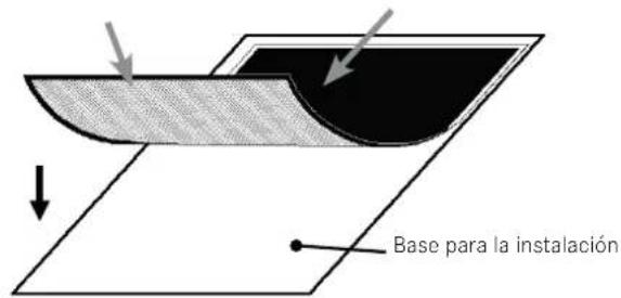
Place the screen front down and completely flat on a clean surface in a horizontal position (figure 3).

natural_image
Line drawing of a hand performing a wrist massage or acupressure technique (no text or symbols present)Figure 1
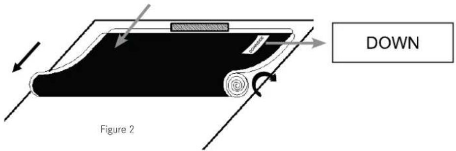
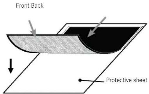
Figure 3
Carefully place the assembled inner frame on the screen. Align the corners of the screen with the corners of the assembled inner frame, as shown in the figure below. To prevent the screen from being pierced, the angled edge of the frame must not come into direct contact with the screen.
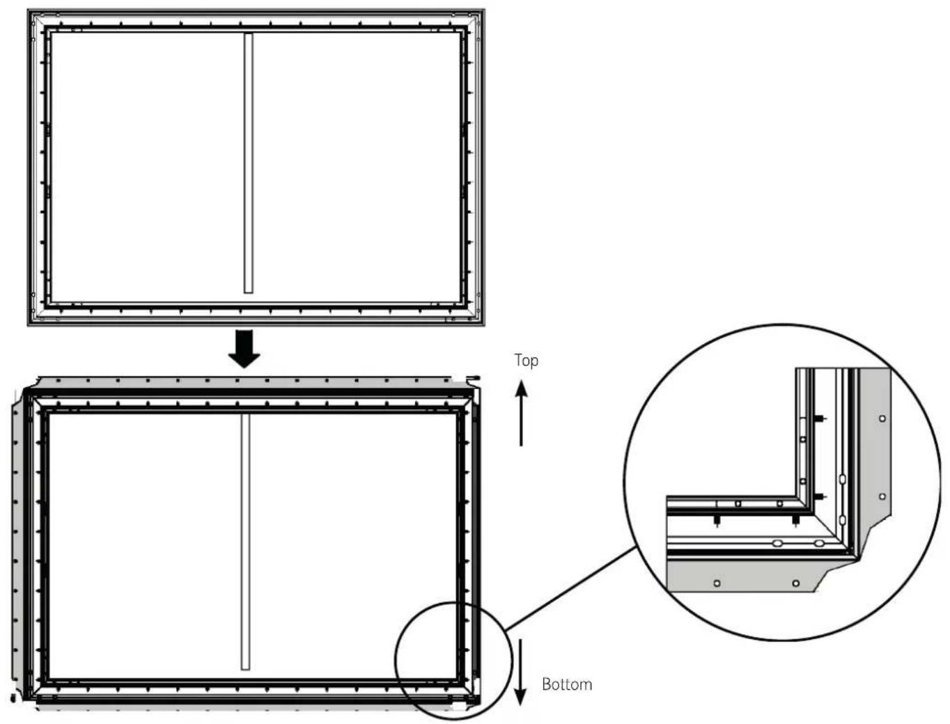
Use the spring hook (X) to attach the inner frame's springs into the holes on the outer edge of the screen. Each hole on the outer edge of the screen goes with one spring.
▶ Start by securing the four corners. Two people should use the spring hook (✗) to attach the springs into the holes on the outer edge of the screen. Please do this in the following order: first 1-1 → 2-2 → 3-3 → 4-4 and then 5-5 → 6-6 → 7-7 → 8-8.
natural_image
Pure architectural or structural diagram of a rectangular frame with vertical and horizontal lines, no text or symbols present.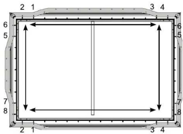
- Note: there is one additional spring on each side that can be used if necessary.
Pull the screen tight in the direction indicated by the arrow.
Use the spring hook (K) to attach the springs into the holes on the horizontal and vertical outer edges of the screen.
Repeat the process until all of the springs have been attached.
- Note: the screen is optimally positioned if the outer edge precisely covers the M4x6 screws (E) indicated above.
Once you have attached the corners of the screen, connect the remaining springs in the order 1 → 2 as shown below.


natural_image
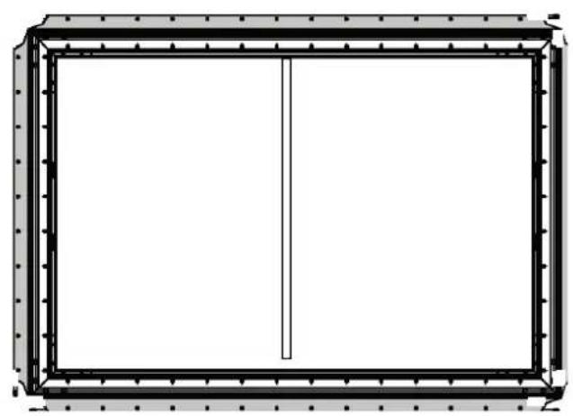
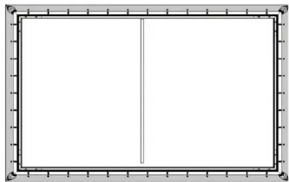
Empty rectangular frame with a vertical line on the left side, surrounded by decorative border (no text or symbols)Once you have completed the steps above, stand up the inner frame with the attached screen and check if the screen protrudes over its edges. If this is the case, release the individual springs and readjust the screen. The screen is correctly positioned if it does not protrude over the edges of the inner frame and all sides run parallel to the sides of the inner frame.
ASSEMBLING THE OUTER FRAME
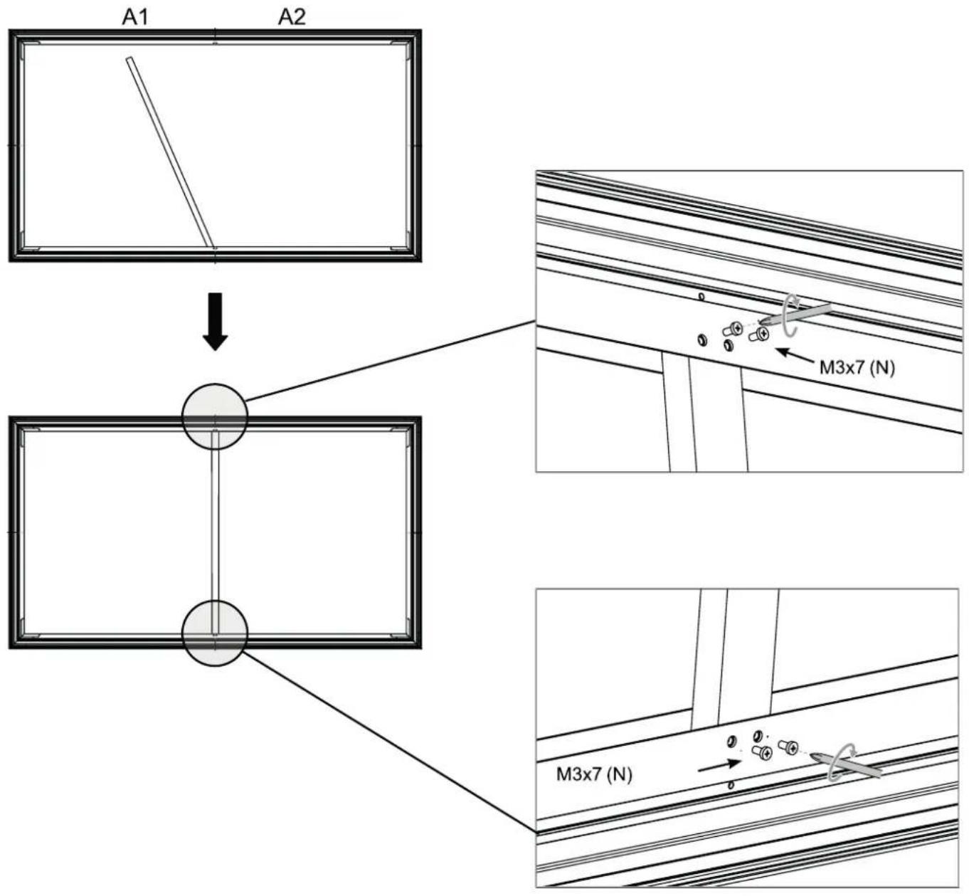
▶ Use the longitudinal connector (S) and the M3x7 screws (N) to connect the outer frame long sides (L1 and L2).
Place all parts of the outer frame around the screen ensuring that the outer frame long side (1) with the logo is at the bottom right.
▶ Position all parts of the outer frame on the edges of the screen. Adjust the cover so the upper and lower cover sections touch and there are no gaps in the middle. Align the M3x7 screws (N) with the holes as shown in the figure below, then insert and loosely tighten them.
Note: when assembling the outer frame, ensure that there is no screen protection paper, foam, non-woven fabric, or other materials on the edge of the screen.
Place the corner connectors (P) on the four corners. Once the corner connectors (P) are fully positioned against the outer frame, fully tighten the screws in the holes.
Note: Do not tighten the corner connectors (P) too firmly as a high torsional force can make them slip. The force should be less than 0.3 Nm.
Six screws need to be used for the outer frame long side and three for the outer frame short side.
- Align the components L1, L2, and M with the corners of the frame and the holes.
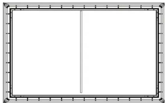
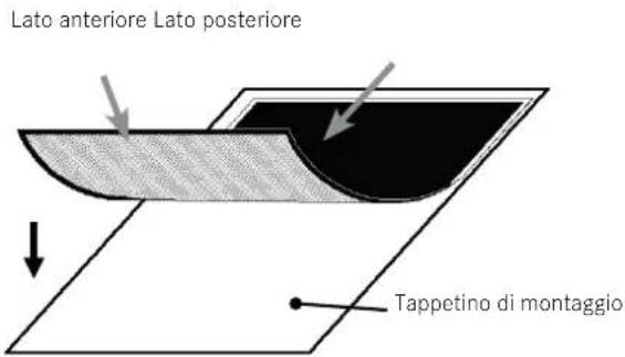
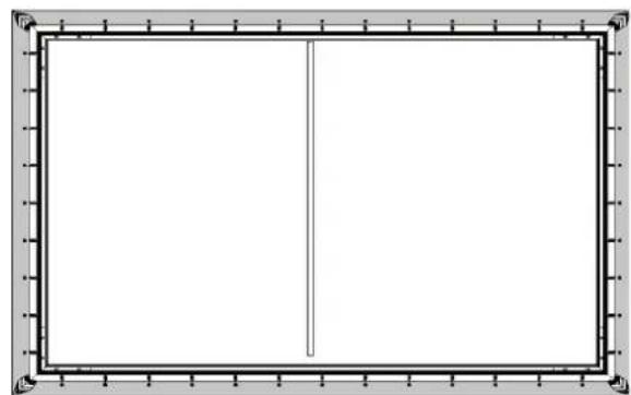
▶ Look at the screen from a horizontal perspective. If the screen looks black, it is correctly positioned and ready to be attached to the wall. If the screen looks white, rotate it and then attach it.
- Once the installation is complete, the front and back of the screen should look as pictured below.
natural_image
Empty white rectangle with a thin black border (no text or symbols)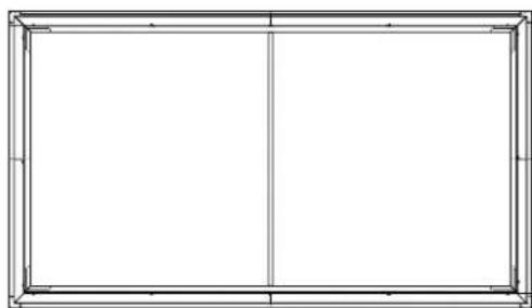
natural_image
Empty rectangular frame with vertical centerline and corner markers (no text or symbols)BackFront
INSTALLING THE WALL BRACKETS
Check the wall type
| Studded drywall Solid concrete or hollow blocks | |
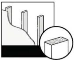 | 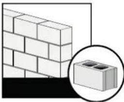 |
| Minimum stud size:standard 51 x 102 mm (2 x 4 inches)nominal 38 x 89 mm ( 112 x 312 inches) | Minimum solid concrete thickness: 203 mm (8 inches)Minimum hollow block size:standard 203 x 203 x 406 mm (8 x 8 x 16 inches)Place the screen on the wall brackets. |
Prepare the room
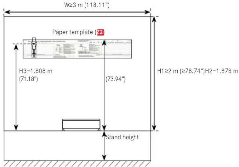
▶ Check the size of your room:
• Width: 3 m (\~118.11 inches)
- Height: 2 m (\~78.74 inches) from the installation area to the ceiling.
- For an optimal visual experience, we recommend a minimum clearance of 4.5 m (177 inches) from the screen.
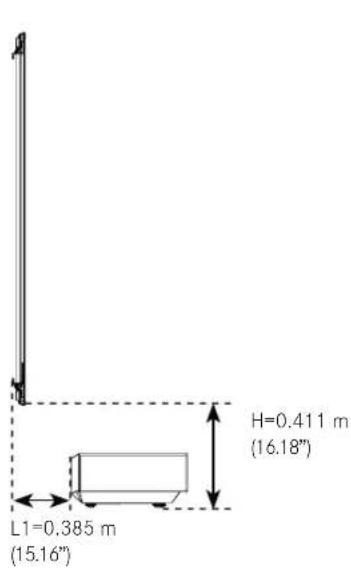
▶ Recommended stand size:
We recommend positioning the Leica Laser TV on a stand measuring approximately 50 cm (20 inches) high by 42 cm (16 inches) wide.
Install the wall bracket
Note: ensure that you have the paper template (72), a pencil, adhesive tape, a spirit level, and a screwdriver to hand.
▶ Measure 1.85 m (73 inches) up from the top edge of the stand for the Leica Laser TV and mark the height with the pencil.
Place the top edge of the paper template in the center of the wall on the mark.
▶ Ensure that the paper template is totally straight.
In the case of a studded drywall
▶ Use a stud detector to find the studs that lie behind the paper template (22). Mark the middle of the studs with a pencil.
▶ Follow the vertical line on the paper template and mark the positions of the lower screws in the suggested area.
▶ Drill holes for the four screws at the marked points.
Remove the paper template and use the screws to fasten the wall brackets (W) in place. Note: hold the wall brackets while tightening the screws to prevent them from slipping.
natural_image
Diagram showing a tool interacting with a panel-like structure, no text or symbols present
In the case of a solid concrete or hollow block wall
▶ Drill holes for the top screws.
▶ Follow the vertical line on the paper template (72) and drill holes for the bottom screws within the intended area.
Remove the paper template and insert four wall plugs ( 21) into the holes.
▶ Ensure that the wall plugs end flush with the wall.
▶ Use the screws to fasten the wall brackets (W) in place.
Note: hold the wall brackets while tightening the screws to prevent them from slipping.
natural_image
Diagram showing a hammer striking a screw with a spring, illustrating the process (no text or symbols present)Note: All screws must be fully tightened to prevent the wall brackets from moving. Ensure that the wall brackets are securely attached to the wall before moving on to the next step.
Attach the connection rod for the wall brackets
Put together the connection rods (Y1, Y2, and Y3) as shown in the figure. Ensure that all parts are straight and tighten the screws.
▶ Hang the connection rods on the wall brackets.
natural_image
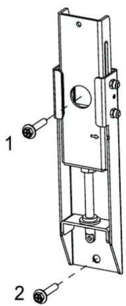
Technical line drawing of a mechanical lock or latch assembly (no text or symbols)HANGING THE SCREEN
We strongly recommend the screen being carried by two people. Always wear gloves (included) to protect the screen against grease, sweat, and dirt.
natural_image
Silhouettes of two people holding a blank rectangular board (no text or symbols)▶ Place the assembled screen on the floor in an upright position.
▶ Look at the screen from a horizontal perspective. If the screen looks black, it is correctly positioned and ready to be attached to the wall. If the screen looks white, rotate it and then attach it.
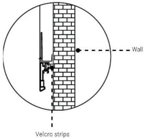
Remove the protective paper on one side of the Velcro strips. Attach the Velcro strips to the bottom left and right of the back of the screen.
natural_image
Pure architectural or structural line drawing of a rectangular frame with vertical and horizontal lines, no text or symbols present.▶ Place the screen on the wall brackets.
Note: The Leica Laser TV should not be ceiling mounted. If you ceiling mount the Leica Laser TV, the orientation of the screen must be rotated. This impairs the ability to compensate for the ambient light.
WARNING: Laser beams can damage the eyes. Do not look directly into the lens of the Leica Laser TV when it is switched on.
Adjust the height of the screen by twisting the adjustment hooks ( X ) and the adjustment rods ( Y ) for the wall brackets. Use the top edge of the screen for guidance to adjust the screen to the displayed image.
natural_image
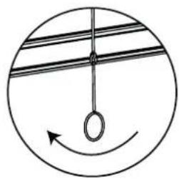
Simple circular diagram with a hanging ring and an arrow, no text or symbols present.If the screen is higher than the image displayed, twist the adjustment hooks clockwise to lower the screen.
natural_image
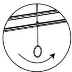
Simple circular diagram with a hanging ring and curved arrow, no text or symbols present.If the screen is lower than the image displayed, twist the adjustment hooks counterclockwise to raise the screen.
▶ Ensure that the screen is completely straight both horizontally and vertically.
Remove the adjustment hooks (X).
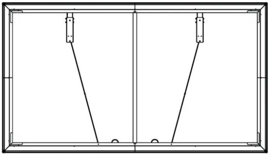
To prevent the adjustment rods from lifting the screen off the wall, fold them up and place them on the brackets at the bottom of the screen (see figure).
natural_image
Pure technical line drawing of a rectangular frame with two vertical supports and two horizontal connectors, no text or symbols present.Once you have fully positioned the screen, remove the protective paper from the other side of the two Velcro strips. Remove the foam bracket and press the screen onto the wall.
Disclaimer:
all products, product specifications and data can be modified without prior announcement to improve the reliability, function, design, or other factors.
TECHNICAL DATA
| Model name Leica Laser TV Screen | |
| Size | 120" |
| Projection area | 2657 × 1494 mm |
| Projection screen fabric | PET+PU |
| Horizontal viewing angle | ≥70° |
| Aspect ratio | 16:9 |
| Screen color | Black |
| Frame color | Black |
| Dimensions (product) | 2697 × 1534 × 31 mm |
| Dimensions (packaging) | 1700 × 492×317 mm |
| Weight | 15.1 kg |
All specified dimensions are approximate values.

KEY INFORMATION
Leica Smart Projection GmbH | Am Leitz-Park 5 | 35578 WETZLAR | GERMANY
Phone +49(0)6441-2080-0 | Fax +49(0)6441-2080-333 | www.leica-lasertv.com
X/22/D

LEICA LASER TV SCREEN
KURZANLEITUNG
QUICK START GUIDE
MODE D'EMPLOI SUCCINCT
BEKNOPTE HANDLEIDING
GUIDA RAPIDA
INSTRUCCIONES ABREVIADAS
КРАТКАЯ ИНСТРУКЦИЯ
AVANT-PROPOS
Chère cliente, cher client,
Remarque
flowchart
graph TD
    A["Rectangle with corners A1, A2, B, C"] -->|→| B["Rectangle with arrow down"]
    B --> C["Rectangle with arrow left"]
MONTAGE DE L'ÉCRAN DE PROJECTION
Remarque
natural_image
Line drawing of a hand holding an object, possibly a wrist or wrist (no text or symbols present)Illustration 1
DOWN
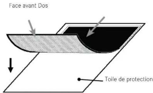
Illustration 3
natural_image
Pure technical diagram of a rectangular frame with internal vertical and horizontal lines, no text or symbols present.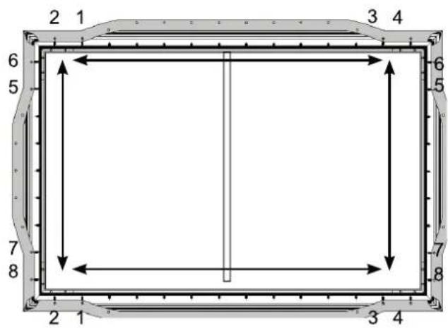


natural_image
Empty rectangular frame with a vertical line on the left side, surrounded by decorative border (no text or symbols)natural_image
Two empty rectangular frames with vertical centerlines, no text or symbols presentDosFace avant
MONTAGE DES FIXATIONS MURALES
natural_image
Diagram showing a tool interacting with a vertical panel and a diagonal line, no text or symbols present
natural_image
Diagram showing a hammer striking a screw with a spring, illustrating the process (no text or symbols present)natural_image
Technical line drawing of a mechanical lock or latch assembly (no text or symbols)SUSPENSION DE L'ÉCRAN DE PROJECTION
natural_image
Silhouette of two people holding a blank rectangular board (no text or symbols)natural_image
Pure architectural line drawing of a rectangular frame with vertical and horizontal lines, no text or symbols presentnatural_image
Simple circular diagram with a hanging ring and curved arrow, no text or symbols present.natural_image
Simple circular diagram with a hanging ring and curved arrow, no text or symbols present.natural_image
Pure technical line drawing of a rectangular frame with two vertical supports and two horizontal connectors, no text or symbols present.BEKNOPTE HANDLEIDING
GUIDA RAPIDA
INSTRUCCIONES ABREVIADAS
КРАТКАЯ ИНСТРУКЦИЯ
VOORWOORD
Geachte klant,
https://leica-camera.com/en-int/contact
LEVERINGSOMVANG
Aanwijzing
BINNENFRAME MONTEREN
flowchart
graph TD
    A["Rectangle with corners A1, A2, B, C"] -->|→| B["Rectangle with arrow down"]
    B --> C["Rectangle with arrow left"]
HET SCHERMDOEK MONTEREN
Aanwijzing
natural_image
Line drawing of a hand performing a wrist massage or acupressure technique (no text or symbols present)Afbeelding 1

natural_image
Pure technical diagram of a rectangular frame with a vertical line inside, no text or symbols present.

natural_image
Empty rectangular frame with a vertical line inside, surrounded by decorative border (no text or symbols)natural_image
Diagram showing a tool interacting with a panel-like structure, no text or symbols present
natural_image
Diagram showing a hammer striking a screw with a spring, no text or symbols present▶ Hang de instelstangen in de wandhouders.
natural_image
Technical line drawing of a mechanical lock or latch assembly (no text or symbols)SCHERM OPHANGEN
natural_image
Silhouettes of two people holding a blank rectangular board (no text or symbols)natural_image
Pure architectural or structural line drawing of a rectangular frame with vertical and horizontal lines, no text or symbols present.natural_image
Simple circular diagram with a hanging ring and curved arrow, no text or symbols present.natural_image
Simple circular diagram with a hanging ring and curved arrow, no text or symbols present.natural_image
Pure technical line drawing of a rectangular frame with two vertical supports and two horizontal connectors, no text or symbols present.BEKNOPTE HANDLEIDING
GUIDA RAPIDA
INSTRUCCIONES ABREVIADAS
КРАТКАЯ ИНСТРУКЦИЯ
PREFAZIONE
Gentile cliente,
https://leica-camera.com/it-IT/contatto
Avvertenza
flowchart
graph TD
    A["Rectangle with corners A1, A2, B, C"] -->|→| B["Rectangle with arrow down"]
    B --> C["Rectangle with arrow left"]
MONTAGGIO DELLO SCHERMO
Avvertenza
natural_image
Line drawing of a hand performing a wrist massage or acupressure technique (no text or symbols present)Figura 1

DOWN
natural_image
Pure technical diagram of a rectangular frame with a vertical line inside, no text or symbols present

natural_image
Empty rectangular frame with a vertical line on the left side, surrounded by decorative border (no text or symbols)natural_image
Diagram showing a tool interacting with a vertical panel and diagonal lines, no text or symbols present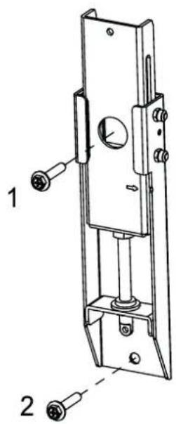
natural_image
Diagram showing a hammer striking a screw with a threaded rod, illustrating the process (no text or symbols present)natural_image
Technical line drawing of a mechanical lock or latch assembly (no text or symbols)APPENDERE LO SCHERMO
natural_image
Silhouette of two people holding a blank rectangular board (no text or symbols)natural_image
Pure architectural line drawing of a rectangular frame with vertical and horizontal lines, no text or symbols presentnatural_image
Simple circular diagram with a hanging ring and curved arrow, no text or symbols present.natural_image
Simple circular diagram with a hanging ring and curved arrow, no text or symbols present.natural_image
Pure technical line drawing of a rectangular frame with two vertical supports and two horizontal connectors, no text or symbols present.BEKNOPTE HANDLEIDING
GUIDA RAPIDA
INSTRUCCIONES ABREVIADAS
КРАТКАЯ ИНСТРУКЦИЯ
INTRODUCCIÓN
Nota
flowchart
graph TD
    A["Rectangle with corners A1, A2, B, C"] -->|→| B["Rectangle with arrow down"]
    B --> C["Rectangle with arrow left"]
MONTAJE DE LA PANTALLA
Nota
natural_image
Line drawing of a hand performing a wrist massage or acupressure technique (no text or symbols present)Figura 1
DOWN
Lado delantero Lado trasero
natural_image
Pure technical diagram of a rectangular frame with internal vertical and horizontal lines, no text or symbols present.
natural_image
Technical diagram of a corner joint with mounting holes and a rotation arrow indicating rotational motion (no text or symbols)natural_image
Technical diagram of a corner joint with mounting hardware (no text or symbols)

natural_image
Empty rectangular frame with a vertical line on the left side, surrounded by decorative border (no text or symbols)natural_image
Diagram showing a tool interacting with a vertical panel and a diagonal line, no text or symbols present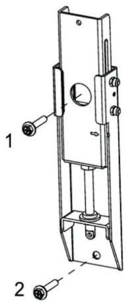
natural_image
Diagram showing a hammer striking a screw with a spring, no text or symbols presentnatural_image
Technical line drawing of a mechanical lock or latch assembly (no text or symbols)COLGAR LA PANTALLA
natural_image
Silhouette of two people holding a blank rectangular board (no text or symbols)natural_image
Pure architectural or engineering diagram showing a rectangular frame with vertical and horizontal lines, and two small rectangular blocks below (no text or symbols)natural_image
Simple circular diagram with a hanging ring and curved arrow, no text or symbols present.natural_image
Simple circular diagram with a hanging ring and curved arrow, no text or symbols present.natural_image
Pure technical line drawing of a rectangular frame with two vertical supports and two horizontal connectors, no text or symbols present.Указание
flowchart
graph TD
    A["Rectangle with corners A1, A2, B, C"] -->|→| B["Rectangle with arrow down"]
    B --> C["Rectangle with arrow left"]
МОНТАЖ ЭКРАНА
Указание
natural_image
Line drawing of a hand performing a wrist-wrist or acupressure technique (no text or symbols present)Рисунок 1

natural_image
Pure technical diagram of a rectangular frame with internal vertical and horizontal lines, no text or symbols present.

natural_image
Empty rectangular frame with a vertical line on the left side, surrounded by decorative border (no text or symbols)natural_image
Two empty rectangular frames with vertical centerlines, no text or symbols presentnatural_image
Diagram showing a tool interacting with a vertical panel and diagonal lines, no text or symbols present