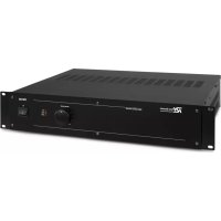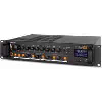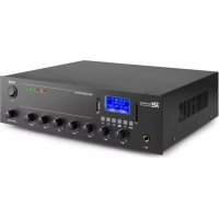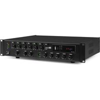
PMP360 - Audio Amplifier Power Dynamics - Free user manual and instructions
Find the device manual for free PMP360 Power Dynamics in PDF.


User questions about PMP360 Power Dynamics
0 question about this device. Answer the ones you know or ask your own.
Ask a new question about this device
Download the instructions for your Audio Amplifier in PDF format for free! Find your manual PMP360 - Power Dynamics and take your electronic device back in hand. On this page are published all the documents necessary for the use of your device. PMP360 by Power Dynamics.
USER MANUAL PMP360 Power Dynamics
Power Dynamics Professional Audio
PMP Series Mixer Amplifier
Ref. nr.: 954.010, 954.012, 954.014, 954.016
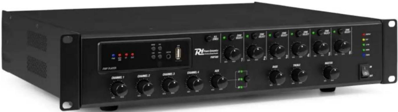
text_image
Rd Power Dynamics RdPPLATE CHANNEL 1 CHANNEL 2 CHANNEL 3 CHANNEL 4 MAIN MAIN MAIN MAIN MAIN MAIN MAIN MAIN MAIN MAIN MAIN MAIN MAIN MAIN MAIN MAIN MAIN MAIN MAIN MAIN MAIN MAIN MAIN MAIN MAIN MAIN MAIN MAIN MAIN MAIN MAIN MAIN MAIN MAIN MAIN MAIN MAIN MAIN MAIN MAIN MAIN MAIN MAIN MAIN MAIN MAIN MAIN MAIN MAIN MAIN RAIN RAIN RAIN RAIN RAIN RAIN RAIN RAIN RAIN RAIN RAIN RAIN RAIN RAIN RAININSTRUCTION MANUAL GEBRUIKSAANWIJZING BEDIENUNGSANLEITUNG MANUAL DE INSTRUCCIONES MANUEL D'INSTRUCTIONS INSTRUKCJA OBSŁUGI NÁVOD K POUŽITÍ
Congratulations to the purchase of this Power Dynamics product. Please read this manual thoroughly prior to using the unit in order to benefit fully from all features.
Read the manual prior to using the unit. Follow the instructions in order not to invalidate the warranty. Take all precautions to avoid fire and/or electrical shock. Repairs must only be carried out by a qualified technician in order to avoid electrical shock. Keep the manual for future reference.
- Prior to using the unit, please ask advice from a specialist. When the unit is switched on for the first time, some smell may occur. This is normal and will disappear after a while.
- The unit contains voltage carrying parts. Therefore, do NOT open the housing.
- Do not place metal objects or pour liquids into the unit This may cause electrical shock and malfunction.
- Do not place the unit near heat sources such as radiators, etc. Do not place the unit on a vibrating surface. Do not cover the ventilation holes.
- The unit is not suitable for continuous use.
- Be careful with the mains lead and do not damage it. A faulty or damaged mains lead can cause electrical shock and malfunction.
- When unplugging the unit from a mains outlet, always pull the plug, never the lead.
- Do not plug or unplug the unit with wet hands.
- If the plug and/or the mains lead are damaged, they need to be replaced by a qualified technician.
- If the unit is damaged to such an extent that internal parts are visible, do NOT plug the unit into a mains outlet and DO NOT switch the unit on. Contact your dealer. Do NOT connect the unit to a rheostat or dimmer.
- To avoid fire and shock hazard, do not expose the unit to rain and moisture.
- All repairs should be carried out by a qualified technician only.
- Connect the unit to an earthed mains outlet (220-240Vac/50Hz) protected by a 10-16A fuse.
- During a thunderstorm or if the unit will not be used for a longer period of time, unplug it from the mains. The rule is: Unplug it from the mains when not in use.
- If the unit has not been used for a longer period of time, condensation may occur. Let the unit reach room temperature before you switch it on.
- For use in humid rooms or outdoors: refer to the installation guidelines for safe assembly.
-
To prevent accidents in companies, you must follow the applicable guidelines and follow the instructions.
-
Do not repeatedly switch the fixture on and off. This shortens the lifetime.
- Keep the unit out of the reach of children. Do not leave the unit unattended.
- Do not use cleaning sprays to clean switches. The residues of these sprays cause deposits of dust and grease. In case of malfunction, always seek advice from a specialist.
- Do not force the controls.
- This unit is with speaker inside which can cause magnetic field. Keep this unit at least 60cm away from computer or TV.
- If this product has a built-in lead-acid rechargeable battery: Please recharge the battery every 3 months if you are not going to use the product for a long period of time. Otherwise, the battery may be permanently damaged.
- If the battery is damaged, please replace with same specifications battery. And dispose the damaged battery environment friendly.
- If the unit has fallen, always have it checked by a qualified technician before you switch the unit on again.
- Do not use chemicals to clean the unit. They damage the varnish. Only clean the unit with a dry cloth.
- Keep away from electronic equipment that may cause interference.
- Only use original spares for repairs, otherwise serious damage and/or dangerous radiation may occur.
- Switch the unit off prior to unplugging it from the mains and/or other equipment. Unplug all leads and cables prior to moving the unit.
- Make sure that the mains lead cannot be damaged when people walk on it. Check the mains lead before every use for damages and faults!
- The mains voltage is 220-240Vac/50Hz. Check if power outlet match. If you travel, make sure that the mains voltage of the country is suitable for this unit.
- Keep the original packing material so that you can transport the unit in safe conditions.

This mark attracts the attention of the user to high voltages that are present inside the housing and that are of sufficient magnitude to cause a shock hazard.

This mark attracts the attention of the user to important instructions that are contained in the manual and that he should read and adhere to.
The unit has been certified CE. It is prohibited to make any changes to the unit. They would invalidate the CE certificate and their guarantee!
NOTE: To make sure that the unit will function normally, it must be used in rooms with a temperature between 5^ C/41°F and 35^ C/95°F.

Electric products must not be put into household waste. Please bring them to a recycling centre. Ask your local authorities or your dealer about the way to proceed. The specifications are typical. The actual values can slightly change from one unit to the other. Specifications can be changed without prior notice.
Do not attempt to make any repairs yourself. This would invalid your warranty. Do not make any changes to the unit. This would also invalid your warranty. The warranty is not applicable in case of accidents or damages caused by inappropriate use or disrespect of the warnings contained in this manual. Power Dynamics cannot be held responsible for personal injuries caused by a disrespect of the safety recommendations and warnings. This is also applicable to all damages in whatever form.
UNPACKING INSTRUCTION
CAUTION! Carefully unpack the box upon receipt. Check the contents to ensure that all parts are present and have been received in good condition. Notify the shipper immediately and retain packaging material if any parts appear damaged from shipping or the package itself shows signs of mishandling. Save the package and all packaging materials. If the product must be returned, it is important that the product is returned in the original factory box and packaging. If the device has been exposed to drastic temperature fluctuation (e.g. after transportation), do not switch it on immediately. The arising condensation water might damage your device. Leave the device switched off until it has reached room temperature.
POWERSUPPLY
The label on the back/under side of the product indicates the mains voltage to which it must be connected. Check that the mains voltage corresponds to this. Any other voltage than the one indicated may cause irreparable damage to the unit. The unit must also be connected directly to the mains voltage and no dimmer or adjustable power supply may be used.

Always connect the device to a protected circuit (circuit breaker or fuse). Make sure the device has an appropriate electrical ground to avoid the risk of electrocution or fire.
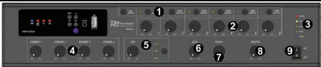
FRONT PANEL
text_image
PROF PLANS 1 2 3 4 5 6 7 8 9 CHANNEL 1 CHANNEL 2 CHANNEL 3 CHANNEL 4 CHANNEL 5 CHANNEL 6 CHANNEL 7 CHANNEL 8 CHANNEL 9- ZONE SELECT
Press to (de)select separate zones, or press ALL ZONES to (de)select all zones at once. - ZONE VOLUME
Rotate to adjust the volume level per zone.
- STATUS INDICATORS
LED status indicators (power, level, protect).
- CHANNEL VOLUME
Rotate to adjust the volume level per channel.
- AUX CONTROLS
Press the button to select AUX (A or B) and media (M) sources. Rotate the knob to adjust the AUX/MEDIA volume level.
- BASS
Rotate to adjust the bass level.
- TREBLE
Rotate to adjust the treble level.
- MASTER VOLUME
Rotate to adjust the master (main) volume.
- POWER ON/OFF
Press to turn the device on/off.
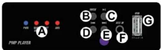
MEDIA PLAYER FRONT
A. STATUS/MODE INDICATORS
LED status and source (mode) indicators (power, WiFi/USB, BT, AUX).
B. MODE
Press to change operating modes.
C. PLAY/PAUSE
Press to start/resume or pause playback.
D. PREVIOUS
Press to change to previous track.
E. NEXT
Press to skip to next track.
F. AUX INPUT
3.5mm input jack for auxiliary input.
G. USB
USB input socket.
text_image
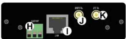
PMP PLAYER A B C D E F GMEDIA PLAYER REAR
H. OUTPUT
Stereo line output connector block.
I. LAN
RJ45 input connector for cabled internet radio function.
J. WIFI ANTENNA
Connector for installing a WiFi antenna.
K. BT ANTENNA
Connector for installing a BT antenna.
text_image
OUTPUT H LAW I WiFi J BT K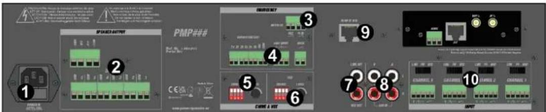
text_image
SPRING OUTPUT PMP### C:\Program Files\Output\Control\Switch\Control\Switch\Control\Switch\Control\Switch\Control\Switch\Control\Switch\Control\Switch\Control\Switch\Control\Switch\Control\Switch\Control\Switch\Control\Switch\Control\Switch\Control\Switch\Control\Switch\Control\Switch\Control\Switch\Control\Switch\Control\Switch\Control\Switch\Control\Switch\Control\Switch\Control\Switch\Control\Switch\Control\Switch\Control\Current Control 1 2 3 4 5 6 7 8 9 10 OUTPUT-
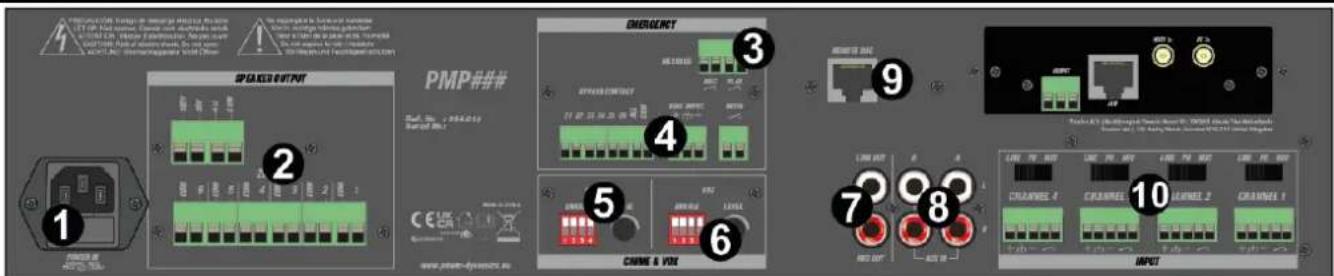
AC IN AND FUSE HOLDER Socket for plugging in the supplied power cord. For instructions on how to change the fuse, see "REPLACING THE FUSE".
-
SPEAKER OUTPUT Speaker output terminal for connecting speakers (individual zones (100V) and 100V, 70V, 4 Ohm).
-
EMERGENCY MESSAGE Terminal to enable the recording or playback of an emergency message.
-
EXTERNAL EVACUATION Terminal to enable an external evacuation message, with options of muting and bypassing individual zones.
-
CHIME Chime enable dip switches and level knob. If a chime on channel 2 is desired, set the channel 2 dip switch to "enable" position. Adjust the chime level by rotating the knob.
-
VOX VOX enable dip switches and level knob. VOX (voice-operated exchange) provides the option to enable a channel when voice input (above a certain threshold) is detected. Set the dip switch(es) to "enable" position to make use of this function.
-
LINK- AND REC OUTPUT RCA connectors for link- and rec output.
-
AUX INPUT RCA connectors for AUX A- and B input (left and right).
-
REMOTE MIC Remote microphone input connector (RJ45).
- CHANNEL INPUT AND INPUT SELECTORS Balanced line/mic input for channel input 1-4, including pre-announcement chime possibility. The inputs are equipped with line, phantom power and microphone setting switches.
Phantom power: set the input switch to PH to supply DC +48V phantom power to accommodate the use of a condenser microphone.
REPLACING THE FUSE
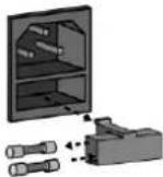
If the fuse is defective, replace the fuse with a fuse of the same type and value. Before replacing the fuse, unplug mains lead.
Procedure: Step 1: Open the fuse holder on the rear panel with a fitting screwdriver. Step 2: Remove the old fuse from the fuse holder. Step 3: Install the new fuse in the fuse holder. Step 4: Replace the fuse holder in the housing.
CONNECTING WITH BT
Connecting your BT-device to the amplifier, follow below steps:
- Turn on BT on your smartphone or tablet.
- Press the MODE button until the BT LED is illuminated.
- Search for "MPlayer A" in the BT menu of the smartphone or tablet.
- Connect with "MPlayer A".
WIFI
Download the latest version of the LEGACY Player app via Apple store or Google play. Here you will also find the latest features and explanations on how to use them.

text_image
QR code image containing encoded data, no visible human-readable textLegacy Player Apple Store

text_image
QR code image containing encoded data, no visible human-readable textLegacy Player Google Play
SPEAKER TERMINALS
These terminals are offering a low voltage output of 4Ω (minimum load). A 100V commercial output is also available. Please note that one wire only should be connected to COM screw and one wire to the selected impedance or voltage.
ATTENTION: Multiple combinations cannot be done at the output level.
Two different types of connections are provided. The low impedance section: 4 (minimum load) is designed for a small amount of speakers to be connected to your amplifier. The 100V section is especially designed for a multiple speaker distribution. When using the 100V output, speakers have to be equipped with a 100V transformer. The maximum amount of speakers to be placed on your distribution line is in relation to the power allocated to each speaker. The total wattage set on the secondary side of the transformers on your speaker line must not exceed the maximum RMS output power of the device. Failure to respect this may cause permanent damage to the amplifier.
OPERATION STEPS
- When all connections to the amplifier are made, turn all rotary controls down and switch on the power (the power LED will illuminate). Turn BASS and TREBLE controls to the 12 o'clock position (pointing straight up) and turn MASTER rotary control up part way for testing.
- Ensure a signal is being fed to one of the inputs and gradually increase the volume control for that channel until the output is heard through the speakers. Turn up the MASTER to the maximum required volume level and reduce the channel volume control if necessary.
Note: The initial test can be made using the built-in USB audio player. The output of the amplifier is represented on the level meter LEDs and care should be taken that the CLIP LED is not (constantly) lit during use. Illumination of this LED may be indicating distortion or clipping of the output signal and the MASTER/MAIN VOLUME should be turned down. - If a microphone is connected, make sure it is switched on and if it requires phantom power, make sure this feature is enabled. Gradually increase its volume control whilst speaking into the microphone until the required volume level is reached. The microphone should not be able to "hear" (detect) the speakers, which can cause feedback (squealing or howling noise).
In addition to channel and MASTER volume controls, there are BASS and TREBLE EQ controls to adjust the tone of the overall output. At the 12 o'clock position, these controls are applying no effect to the signal (no boost or cut). Rotating the BASS control clockwise boosts the low frequencies in the audio, whilst rotating it anticlockwise will cut these low frequencies. Likewise, rotating the TREBLE control clockwise boosts the high frequencies in the audio, whilst rotating it anticlockwise will cut these high frequencies. Adjust these EQ controls to suit the type of audio signal or compensate for the room acoustics.
- Normally, playback will start automatically when a USB stick is inserted in the corresponding slot. If not, select USB by pressing MODE to initiate the USB mode manually. Press PLAY / PAUSE to start playback. Press PREVIOUS and/or NEXT to change tracks.
100V LINE SYSTEM
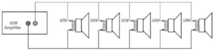
For 100V line systems, connect the amplifier to the first speaker in the system using double-insulated speaker wire which has adequate current rating to handle the total output of the amplifier.
Connect the "100V" output terminal to the positive (+) connection of the speaker and "COM" output to the negative (-) connection of the speaker. Connect further speakers in parallel to the first speaker with all positive terminals and connected together and all negative terminals connected together as shown below.
text_image
60W Amplifier 10W 10W 10W 10W 10WA 100V line speaker system can comprise of many speakers connected together. The determining factor for how many speakers can be used on a single amplifier is the power rating. For most purposes, it is advised to connect as many speakers as needed with a combined wattage of no more than 90% of the amplifier's output power rating. The terminals of a 100V speaker are connected to a transformer and in some cases, this transformer may be “tapped” for different power ratings. These tapings can be used to adjust the wattage (and output volume) of each speaker in the system to help achieve the ideal total power of the system for the amplifier.
text_image
OUTPUT H LAN I J WiFi BT KACHTERPANEEL
text_image
1 2 3 4 5 6 7 8 9 10 PMP### EMERGENCY SPRING SWITCH RUN OUT RUN OUT RUN OUT RUN OUT RUN OUT RUN OUT RUN OUT RUN OUT RUN OUT RUN OUT RUN OUT RUN OUT RUN OUT RUN OUT RUN OUT RUN OUT RUN OUT RUN OUT RUN OUT RUN OUT RUN OUT RUN OUT RUN OUT RUN OUT RUN OUT RUN OUT RUN OUT RUN OUT RUN OUT RUN OUT RUN OUT RUN OUT RUN OUT RUN OUT1. STROOMINGANG EN ZEKERINGHOUDER
4. EVACUATIE (EXTERN)
text_image
QR code image containing encoded data, no visible human-readable textLegacy Player Apple Store

text_image
QR code image containing encoded data, no visible human-readable textLegacy Player Google Play
LUIDSPREKERAANSLUITINGEN
text_image
OUTPUT H LAN J WiFi th BT th K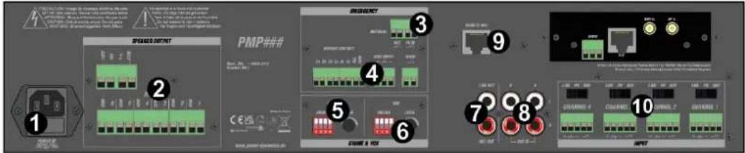
text_image
1 2 3 4 5 6 7 8 9 10 PMP### C#E SWEER SWEER SWEER SWEER SWEER SWEER SWEER SWEER SWEER SWEERtext_image
QR code image containing encoded data, no visible human-readable textLegacy Player Apple Store

text_image
QR code image containing encoded data, no visible human-readable textLegacy Player Google Play
text_image
QR code image containing encoded data, no visible human-readable text
text_image
QR code image containing encoded data, no visible human-readable textLegacy Player Apple Store
Legacy Player Google Play
text_image
PMP PLAYER A B C D E F G H I J K L M N O P Q R S T U V W X Y Z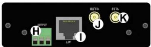
text_image
OUTPUT LUN WIFTh J BTTh K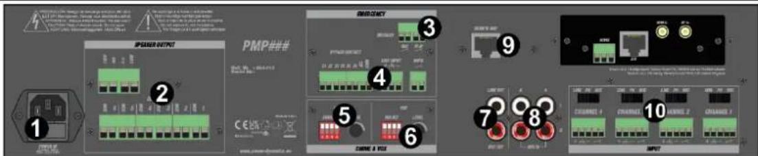
text_image
SPAPER INPUT PMP### C E# SPAPER INPUT SPAPER C E# SPAPER C E# SPAPER C E# SPAPER C E# SPAPER C E# SPAPER C E# SPAPER C E# SPAPER C E# SPAPER C E# SPAPER C E# SPAPER C E# SPAPER C E# SPAPER C E# SPAPER C E# SPAPER C E# SPAPER C E# SPAPER C E# SPAPER S S S S S S S S S S S S S S S S S S S S S S S S S S S S S S S S S S S S S S S S S S S S S S S S S S 11. ENTRÉE AC ET PORTE-FUSIBLE
REPLACEMENT DU FUSIBLE
text_image
QR code image containing encoded data, no visible human-readable textLegacy Player Apple Store

text_image
QR code image containing encoded data, no visible human-readable textLegacy Player Google Play
BORNES DU HAUT-PARLEUR
text_image
QR code image containing encoded data, no visible human-readable textLegacy Player Apple Store

text_image
QR code image containing encoded data, no visible human-readable textLegacy Player Google Play
ZACISKI GŁOŚNIKOWE
text_image
OUTPUT H LAN I WIFI b J RT b K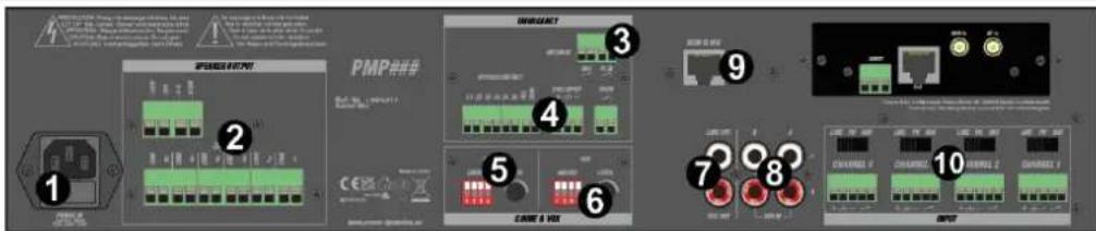
text_image
Diagram showing 10 labeled electrical panel components with Chinese annotations and icons, likely illustrating a power system or network configuration.- VSTUP STRÍDAVÉHO PROUDU A DRŽÁK POJISTEK
text_image
QR code image containing encoded data, no visible human-readable textLegacy Player Apple Store

text_image
QR code image containing encoded data, no visible human-readable textLegacy Player Google Play
The specifications are typical. The actual values can slightly change from one unit to the other. Specifications can be changed without prior notice.
The products referred to in this manual conform to the European Community Directives to which they are subject:
European Union
Tronios B.V.,
7602KR Almelo, The Netherlands
2014/35/EU
2014/30/EU
2011/65/EC
2014/53/EU

United Kingdom
Tronios Ltd.,
130 Harley Street,
London W1G 7JU, United Kingdom
S.I. 2016:1101
S.I. 2016:1091
S.I. 2012:3032
S.I. 2017:1206

Specifications and design are subject to change without prior notice.
www.tronios.com
Copyright © 2023 by TRONIOS the Netherlands