GF500mmF5.6 R LM OIS WR - Lens FUJIFILM - Free user manual and instructions
Find the device manual for free GF500mmF5.6 R LM OIS WR FUJIFILM in PDF.

| Product type | Telephoto super telephoto lens |
| Brand | Fujifilm |
| Model | GF500mmF5.6 R LM OIS WR |
| Mount | FUJIFILM G (exclusive, not compatible with X mount) |
| Focal length | 500 mm (396 mm equivalent in 35 mm) |
| Maximum aperture | f/5.6 |
| Minimum aperture | f/32 |
| Optical construction | 21 elements in 14 groups (5 ED elements, 2 Super ED elements) |
| Field of view | 6.3° |
| Minimum focusing distance | 2.75 m (from the focal plane) |
| Maximum magnification | 0.2× |
| Filter diameter | 95 mm |
| Dimensions (Diameter × Length) | ø104.5 × 246.5 mm |
| Weight (without accessories) | 1375 g |
| Image stabilization | OIS (Optical Image Stabilization) with ON/OFF switch |
| Focus | Linear motor, autofocus, manual, with focus control buttons, AF-L/AF/PRESET selector |
| Focus range | Selectable: FULL or 5m–∞ |
| Power supply | Powered by the camera via mount contacts |
| Supplied accessories | Front cap, rear cap, lens hood, strap, lens case, tripod collar |
| Maintenance and cleaning | Dust blower, soft cloth and optical cleaner for stains, avoid organic solvents; store in a cool, dry place |
| Weather sealing | Rubber ring at mount protects against dust and splashes (replaceable at service center) |
| Safety | Do not look at the sun through the lens; do not immerse; do not disassemble; avoid high temperatures and humidity |
| Spare parts and repairability | Replaceable sealing ring; maintenance by qualified personnel; contact FUJIFILM representative |
| General information | Compliant with FCC (Class B) and ICES-003 regulations; recycle at a collection point or store |
Frequently Asked Questions - GF500mmF5.6 R LM OIS WR FUJIFILM
User questions about GF500mmF5.6 R LM OIS WR FUJIFILM
0 question about this device. Answer the ones you know or ask your own.
Ask a new question about this device
Download the instructions for your Lens in PDF format for free! Find your manual GF500mmF5.6 R LM OIS WR - FUJIFILM and take your electronic device back in hand. On this page are published all the documents necessary for the use of your device. GF500mmF5.6 R LM OIS WR by FUJIFILM.
USER MANUAL GF500mmF5.6 R LM OIS WR FUJIFILM
https://fujifilm-x.com/ja-jp/support/download/firmware/
JA-5
ストラップの取り付け方
レンズフードの取り外し方
PL フィルターの使い方
natural_image
Technical illustration of a mechanical component with an arrow indicating assembly direction (no text or symbols)natural_image
Technical illustration of a cylindrical connector with internal components and directional arrows (no text or symbols)natural_image
Diagram showing two views of a camera lens assembly with adjustment parts (no text or symbols)三脚座について
Be sure to read these notes before use
Safety Notes
Thank you for your purchase of this product. For repair, inspection, and internal testing, contact your FUJIFILM dealer.
• Make sure that you use the lens correctly. Read these safety notes and the camera Owner's Manual carefully before use.
• After reading these safety notes, store them in a safe place.
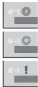
About the Icons
The icons shown below are used in this document to indicate the severity injury or damage that can result if the formation indicated by the icon is ignored and the product is used incorrectly as a result.
| This icon indicates that death or serious injury can result if the information is ignored. | |
| This icon indicates that personal injury or material damage can result if the information is ignored. |
The icons shown below are used to indicate the nature of the instructions which are to be observed.
| Triangular icons tell you that this information requires attention ("Important"). | |
| if the | Circular icons with a diagonal bar tell you that the action indicated is prohibited ("Prohibited"). |
| Filled circles with an exclamation mark indicate an action t be performed ("Required"). |
| WARNING | |
| Do not use in the bathroom or shower | Do not immerse in or expose to water.Failure to observe this precaution can cause a fi re or electric shock. |
| Do not disassemble | Do not disassemble.Failure to observe this precaution can cause fi re, electric shock, or injury due to product malfunction. |
| Do not touch internal parts must | Should the case break open as the result of a fall or other accident, do not touch the exposed parts.Failure to observe this precaution could result in electric shock or in injury from touching the damaged parts.Remove the camera battery immediately, taking care to avoid injury or electric shock, and take the product to the point of purchase for consultation. |
| Do not place on unstable surfaces.The product may fall, causing injury. | |

WARNING

Do not view the sun through the lens or camera viewf nders. Failure to observe this precaution can cause permanent visual impairment.

CAUTION

Do not use or store in locations that are exposed to steam, or smoke or are very humid or extremely dusty. Failure to observe this precaution can cause fire or electric shock.

Do not leave in direct sunlight or in locations subject to very high temperatures, such as in a closed vehicle on a sunny day. Failure to observe this precaution can cause fi re.

Keep out of the reach of small children. This product could cause injury in the hands of a child.

Do not handle with wet hands. Fail ure to observe this precaution can cause electric shock.

CAUTION

Keep the sun out of the frame when shooting backlit subjects. Sunlight focused into the camera when the sun is in or close to the frame can cause fire or burns.

When the product is not in use, replace the lens caps and store out of direct sunlight. Sunlight focused by the lens can cause fire or burns.

Do not carry the camera or lens while they are attached to a tripod. The product can fall or strike other objects, causing injury.

Do not rapidly rotate the camera while holding the grip. Your hand could strike the tripod or tripod collar foot, causing injury.

Before handling the camera, fully tighten or loosen the tripod collar ring-locking knob according to whether the camera will be used in a fixed orientation or rotated. If the knob is only partially tightened, the camera may move unexpectedly, causing injury.
For Customers in the U.S.A.
Tested To Comply With FCC Standards FOR HOME OR OFFICE USE
FCC Statement: This device complies with Part 15 of the FCC Rules. Operation is subject to the following two conditions: (1) This device may not cause harmful interference, and (2) this device must accept any interference received, including interference that may cause undesired operation.
CAUTION: This equipment has been tested and found to comply with the limits for a Class B digital device, pursuant to Part 15 of the FCC Rules. These limits are designed to provide reasonable protection against harmful interference in a residential installation. This equipment generates, uses, and can radiate radio frequency energy and, if not installed and used in accordance with the instructions, may cause harmful interference to radio communications. However, there is no guarantee that interference will not occur in a particular installation. If this equipment does cause harmful interference to radio or television reception, which can be determined by turning the equipment off and on, the user is encouraged to try to correct the interference by one or more of the following measures:
- Reorient or relocate the receiving antenna.
- Increase the separation between the equipment and receiver.

EN-2ENGLI
- Connect the equipment into an outlet on a circuit different from that to which the receiver is connected.
- Consult the dealer or an experienced radio/TV technician for help.
- You are cautioned that any changes or modifications not expressly approved in this manual could void the user's authority to operate the equipment.
Notes on the Grant: To comply with Part 15 of the FCC Rules, this product must be used with a Fujifi Im-specific ed ferrite-core A/V cable, USB cable, and DC supply cord.
For Customers in Canada
CAN ICES-003 (B)/NMB-003(B)
CAUTION: This Class B digital apparatus complies with Canadian ICES-003.
IMPORTANT SAFETY INSTRUCTIONS
- Read these instructions.
- Keep these instructions.
- Heed all warnings.
- Follow all instructions.
- Do not use this apparatus near water (excluding waterproof products).
- Clean only with a dry cloth.
-
Do not block any ventilation openings. Install in accordance with the manufacturer's instructions.
-
Do not install near any heat sources such as radiators, heat registers, stoves, or other apparatus (including amplifiers) that produce heat.
- Protect the power cord from being walked on or pinched particularly at plugs, convenience receptacles, and the point where they exit from the apparatus.
- Only use attachments/accessories specified by the manufacturer.
- Unplug this apparatus during lightning storms or when unused for long periods of time.
- Refer all servicing to qualified service personal. Servicing is required when the apparatus has been damaged in any way, such as power supply cord or plug is damaged, liquid has been spilled or objects have fallen into the apparatus, the apparatus has been exposed to rain or moisture, does not operate normally, or has been dropped.
Disposal of Electrical and Electronic Equipment in Private Households
In the European Union, Norway, Iceland and Liechtenstein: This symbol on the product, or in the manual and in the warranty, and/or on its packaging indicates that this product shall not be treated as household waste. Instead it should be taken to an applicable collection point for the recycling of electrical and electronic equipment.

By ensuring this product is disposed of correctly, you will help prevent potential negative consequences to the environment and human health, which could otherwise be caused by inappropriate waste handling of this product.
The recycling of materials will help to conserve natural resources. For more detailed information about recycling this product, please contact your local city office, your household waste disposal service or the shop where you purchased the product.
In Countries Outside the European Union, Norway, Iceland and Liechtenstein: If you wish to discard this product, including the batteries or accumulators, please contact your local authorities and ask for the correct way of disposal.
U.K. Importer:
FUJIFILM UK Limited
Fujifi Im House, Whitbread Way, Bedford,
Bedfordshire, MK42 0ZE, United Kingdom
EU Importer:
FUJIFILM Electronic Imaging Europe GmbH Fujistrasse 1 47533 Kleve, Germany
Australian RCM

EN-3 ENGLISH
Before Using This Product
The lens may not perform as expected and some features may not be available with outdated lens or camera fi rmware. Be sure to update the lens and camera fi rmware to the latest versions. Instructions on viewing fi rmware version information and updating fi rmware are available from the following website:
https://fujifilm-x.com/support/download/firmware/
If you do not have access to a computer, support is available from the local distributor listed in the "FUJIFILM Worldwide Network" material provided with your camera.
Product Care
- When using a lens hood, do not pick up or hold the camera using only the hood.
- Keep the lens signal contacts clean.
- Use a blower to remove dust and lint from the
glass surfaces of the lens or fi lter. To remove smudges and fi ingerprints, apply a small amount of lens cleaner to a soft, clean cotton cloth or lens-cleaning tissue and clean from the center outwards using a circular motion, taking care not to leave smears or touch the glass with your fi ngers.
- Never use organic solvents such as paint thinner or benzene to clean the lens.
- Attach the front and rear caps when the lens is not in use.
- Store the lens and fi Iter in cool, dry locations to prevent mold and rust. Do not store in direct sunlight or with naphtha or camphor moth balls.
- Keep the lens dry. Rusting can cause irreparable damage. Wipe off rain and water droplets.
• Leaving the lens in extremely hot locations could cause damage or warping. - Note that depending on the positions of the camera and tripod, the hand holding the camera grip may contact the tripod or tripod collar foot when the camera is rotated.
Parts of the Lens
GF500mmF5.6 R LM OIS WR

① The lens mount includes a rubber ring to ensure that the lens remains dust- and splash-proof. The ring can be replaced for a fee at any Fujifi lm service center.
① Lens hood
② Hood latch release
③ Mounting marks
④ Focus control button (×4)
⑤ Focus ring
⑥ Aperture ring
⑦ Aperture ring lock release
⑧ Orientation index (on lens)
⑨ Tripod collar reference index (on collar)
⑩ Tripod collar ring-locking knob
⑪ Mounting marks (focal length)
⑫ Focus range selector
⑬ Focus preset button
⑭ Focus selector
⑮ O.I.S. switch
⑯ Strap eyelet
⑰ Lens signal contacts
⑱ Filter access port
⑲ Tripod collar-locking knob
⑳ Tripod collar foot
②1 Tripod collar release lever
②2 Front lens cap
②3 Rear lens cap
Supplied Accessories
- Front lens cap
- Lens hood
- Rear lens cap
- Lens pouch
- Shoulder strap
- Tripod Collar Foot
Attaching the Lens
See the camera manual for information on attaching and removing lenses.
① This lens is for use exclusively with FUJIFILM G mounts and can not be used with X mounts.
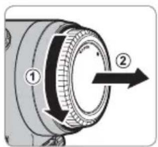
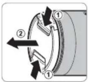
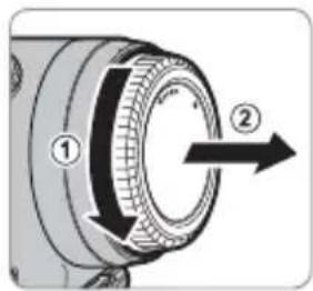
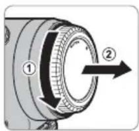
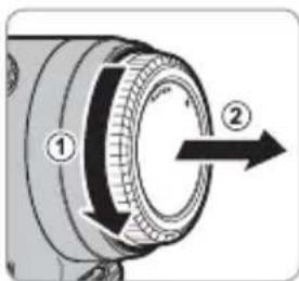
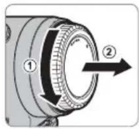
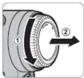
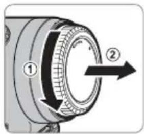
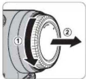
Removing the Caps
Remove the caps as shown.
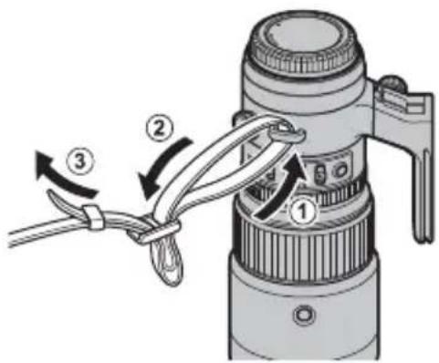
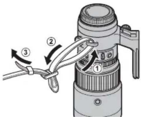
Attaching the Shoulder Strap
Attach the strap to the two strap eyelets as shown.
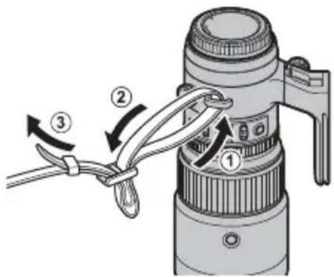
① To avoid dropping the lens, be sure the strap is correctly secured.
① Use the lens strap, not the camera strap, when carrying the camera with the lens attached.
Attaching the Hood
When attached, lens hoods reduce glare and protect the front lens element.
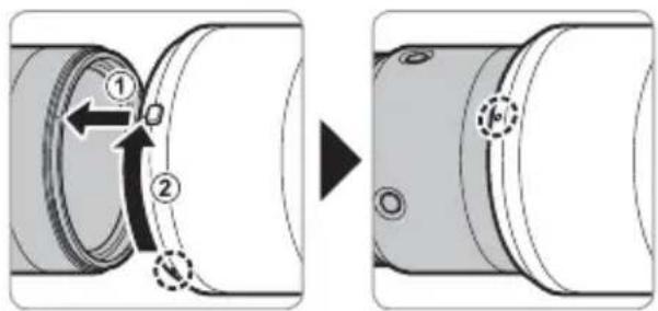
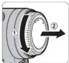
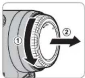
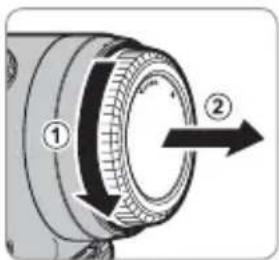
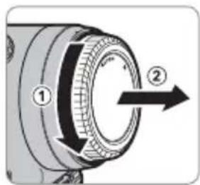
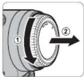
Removing the Hood
To remove the hood, press and hold the hood latch release while rotating the hood counterclockwise.
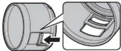
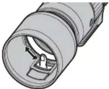
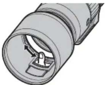
The Polarizing Filter
To access the polarizing fi Iter, open the fi Iter access port cover.
natural_image
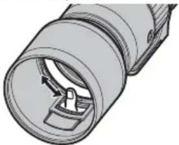
Technical illustration of a mechanical component with an arrow indicating a detail (no text or symbols present)The filter can be rotated by inserting a finger through the access port.
natural_image
Technical illustration of a cylindrical connector with internal slots and a handle (no text or symbols)① Note that the port cover could move and catch your finger.
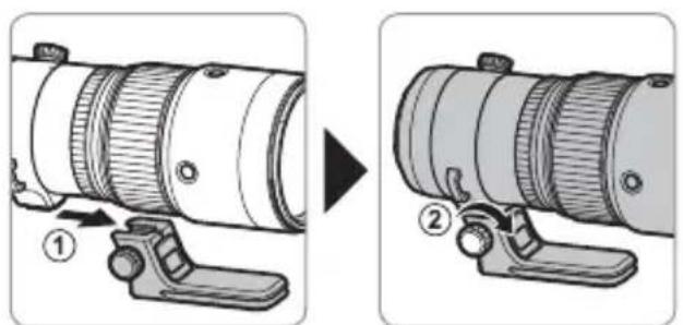
Attaching the Tripod Collar Foot
Slide the lens tripod collar ring fully into the tripod collar foot ^① . Tighten the tripod collar-locking knob ^② to fasten it in place.
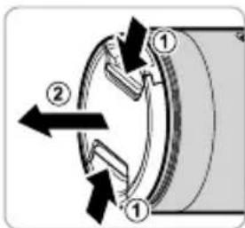
Removing the Tripod Collar Foot
Loosen the tripod collar-locking knob (①) and keep the tripod collar release lever pressed (②) while sliding the tripod collar foot from the lens (③).
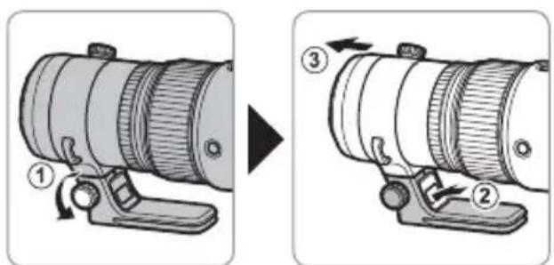
① The foot cannot be securely fastened if orientated incorrectly. Orient the foot as shown in the illustration.
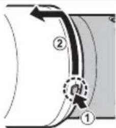
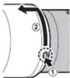
The Tripod Collar
To rotate the camera to take pictures in "tall" (portrait) or "wide" (landscape) orientation, loosen the tripod collar ring-locking knob.
① Tighten the tripod collar ring-locking knob to prevent the camera rotating unexpectedly.
The Focus Range Selector
Choose the focus range for autofocus.

• FULL: Focus on subjects at any distance.
- 5m–∞: Focus on subjects at distances of 5 m or more. Focus is faster than when FULL is selected.
Optical Image Stabilization (OIS)
To use optical image stabilization, slide the O.I.S. switch to ON.
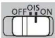
Because image stabilization is also effective in reducing blur caused by the motion of the mechanical shutter, we recommend that you enable optical image stabilization even when using a tripod.
The Focus Control Buttons, Focus Selector, and Focus Preset Button
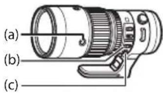
AF-LOCK (Focus Lock)
1 Slide the focus selector (b) to AF-L.
2 Press any of the focus control buttons (a) to lock focus at the current position.
Focus can also be locked using camera controls.
Autofocus (AF-ON)
1 Slide the focus selector (b) to AF.
2 The focus control buttons (a) will now perform the same function as the camera AF-ON button.
EN-9 ENGLISH
PRESET (Focus Preset)
① Creating a Focus Preset
To save the current focus position in the lens as a focus preset, press the focus preset button (c).
The focus distance can be saved with the focus selector (b) in any position.
② Recalling the Focus Preset
1 Slide the focus selector (b) to PRESET.
2 Press any focus control button (a) to restore the preset focus position.
Status is shown in the camera LCD monitor.
- Preset saved (green)
- Preset recalled (green)
- Preset save/load error (blinks red)
The lens will store the preset focus distance even when the camera is off or the lens is removed from the camera.
If ON is selected for AF+MF, pressing a focus control button will return the lens to the preset focus position even while the shutter button is pressed halfway.
Specifications
| Type GF500mmF5.6 R LM OIS WR | |
| Lens construction | 21 elements in 14 groups (5 ED elements, 2 super ED elements) |
| Focal length (35 mm format equivalent) f= | 500mm (396mm) |
| Angle of view 6.3° | |
| Max. aperture f/5.6 | |
| Min. aperture f/32 | |
| Aperture control | |
| Number of blades | 9 (rounded diaphragm opening) |
| Stop size | 13 EV (16 stops) |
| Minimum focus distance (measured from focal plane) | 2.75 m |
| Max. magnifi cation 0.2 × | |
| External dimensions: Diameter × Length* (approx.) * distance from front of lens to lens mount fl ange | ∅104.5 × 246.5 mm |
| Weight* (approx.) * excluding caps, hoods, and tripod collar feet | 1375 g |
| Filter size | ∅95 mm |
① Improvements may result in unannounced changes to specifications and appearance.
① Owing to how this lens is constructed, the "Distance indicator" displayed by the camera may in some cases differ from the actual focus distance. Use the "Distance indicator" as a guide only.
This lens uses linear motors to ensure fast and accurate auto focus while maintaining the highest image quality. When the camera is turned off, the lens is disconnected from the camera body, or the playback feature is turned on, there may be an audible sound and slight physical vibration due to the linear motor's magnets being disengaged. This is perfectly normal and will not negatively affect image quality or lens performance.
To reduce blurring due to vibration from the mechanical shutter, enable E-FRONT CURTAIN SHUTTER or ELECTRONIC SHUTTER in the camera menus.
Pour votre sécurité
https://fujifilm-x.com/support/download/firmware/
natural_image
Technical illustration of a mechanical component with an arrow indicating assembly or adjustment (no text or symbols present)natural_image
Technical illustration of a cylindrical mechanical component with internal channels and a handle (no text or symbols)The Ground Truth image displays a single, solid horizontal line. According to Rule 2 (UNDERSCORE & LINE RULES), if the GT contains lines used for stylistic emphasis or as background elements (like ruled paper), the OCR result must ignore them. The OCR content provided is "____", which represents four underscores. This is incorrect because underscores are not equivalent to a solid line and are not permitted under the “Stylistic/Background Lines (Ignore)” rule. The OCR has hallucinated text (underscores) where none should exist, violating the rule to ignore stylistic lines. Therefore, the OCR result is inconsistent with the Ground Truth.

The Ground Truth image displays a single, solid horizontal line. According to Rule 2 (UNDERSCORE & LINE RULES), if the GT contains lines used for stylistic emphasis or as background elements (like ruled paper), the OCR result must ignore them. The line in the GT is clearly a stylistic or background line, not a placeholder for text. Therefore, the OCR should not have output any underscores. Outputting `____` constitutes an error under Rule 2, as it hallucinates placeholder symbols where none are semantically intended. Hence, the OCR result is inconsistent with the Ground Truth.

The Ground Truth image displays a single, solid horizontal line. According to Rule 2 (UNDERSCORE & LINE RULES), if the GT contains lines used for stylistic emphasis or as background elements (like ruled paper), the OCR result must ignore them. The line in the GT is clearly a stylistic or background line, not a placeholder for text. Therefore, the OCR should not have output any underscores. Outputting `____` constitutes an error under Rule 2, as it hallucinates placeholder symbols where none are semantically intended. Hence, the OCR result is inconsistent with the Ground Truth.

The Ground Truth image displays a single, solid horizontal line. According to Rule 2 (UNDERSCORE & LINE RULES), if the GT contains lines used for stylistic emphasis or as background elements (like ruled paper), the OCR result must ignore them. The line in the GT is clearly a stylistic or background line, not a placeholder for text. Therefore, the OCR should not have output any underscores. Outputting `____` constitutes an error under Rule 2, as it hallucinates placeholder symbols where none are semantically intended. Hence, the OCR result is inconsistent with the Ground Truth.

The Ground Truth image displays a single, solid horizontal line. According to Rule 2 (UNDERSCORE & LINE RULES), if the GT contains lines used for stylistic emphasis or as background elements (like ruled paper), the OCR result must ignore them. The OCR content provided is "____", which represents four underscores. This is incorrect because underscores are not equivalent to a solid line and are not permitted under the “Stylistic/Background Lines (Ignore)” rule. The OCR has hallucinated text (underscores) where none should exist, violating the rule to ignore stylistic lines. Therefore, the OCR result is inconsistent with the Ground Truth.

The Ground Truth image displays a single, solid horizontal line. According to Rule 2 (UNDERSCORE & LINE RULES), if the GT contains lines used for stylistic emphasis or as background elements (like ruled paper), the OCR result must ignore them. The line in the GT is clearly a stylistic or background line, not a placeholder for text. Therefore, the OCR should not have output any underscores. Outputting `____` constitutes an error under Rule 2, as it hallucinates placeholder symbols where none are semantically intended. Hence, the OCR result is inconsistent with the Ground Truth.

The Ground Truth image displays a single, solid horizontal line. According to Rule 2 (UNDERSCORE & LINE RULES), if the GT contains lines used for stylistic emphasis or as background elements (like ruled paper), the OCR result must ignore them. The line in the GT is clearly a stylistic or background line, not a placeholder for text. Therefore, the OCR should not have output any underscores. Outputting `____` constitutes an error under Rule 2, as it hallucinates placeholder symbols where none are semantically intended. Hence, the OCR result is inconsistent with the Ground Truth.

The Ground Truth image displays a single, solid horizontal line. According to Rule 2 (UNDERSCORE & LINE RULES), if the GT contains lines used for stylistic emphasis or as background elements (like ruled paper), the OCR result must ignore them. The line in the GT is clearly a stylistic or background line, not a placeholder for text. Therefore, the OCR should not have output any underscores. Outputting `____` constitutes an error under Rule 2, as it hallucinates placeholder symbols where none are semantically intended. Hence, the OCR result is inconsistent with the Ground Truth.

The Ground Truth image displays a single, solid horizontal line. According to Rule 2 (UNDERSCORE & LINE RULES), if the GT contains lines used for stylistic emphasis or as background elements (like ruled paper), the OCR result must ignore them. The line in the GT is clearly a stylistic or background line, not a placeholder for text. Therefore, the OCR should not have output any underscores. Outputting `____` constitutes an error under Rule 2, as it hallucinates placeholder symbols where none are semantically intended. Hence, the OCR result is inconsistent with the Ground Truth.

The Ground Truth image displays a single, solid horizontal line. According to Rule 2 (UNDERSCORE & LINE RULES), if the GT contains lines used for stylistic emphasis or as background elements (like ruled paper), the OCR result must ignore them. The line in the GT is clearly a stylistic or background line, not a placeholder for text. Therefore, the OCR should not have output any underscores. Outputting `____` constitutes an error under Rule 2, as it hallucinates placeholder symbols where none are semantically intended. Hence, the OCR result is inconsistent with the Ground Truth.

The Ground Truth image displays a single, solid horizontal line. According to Rule 2 (UNDERSCORE & LINE RULES), if the GT contains lines used for stylistic emphasis or as background elements (like ruled paper), the OCR result must ignore them. The OCR content provided is "____", which represents four underscores. This is incorrect because underscores are not equivalent to a solid line and are not permitted under the “Stylistic/Background Lines (Ignore)” rule. The OCR has hallucinated text (underscores) where none should exist, violating the rule to ignore stylistic lines. Therefore, the OCR result is inconsistent with the Ground Truth.

The Ground Truth image displays a single, solid horizontal line. According to Rule 2 (UNDERSCORE & LINE RULES), if the GT contains lines used for stylistic emphasis or as background elements (like ruled paper), the OCR result must ignore them. The line in the GT is clearly a stylistic or background line, not a placeholder for text. Therefore, the OCR should not have output any underscores. Outputting `____` constitutes an error under Rule 2, as it hallucinates placeholder symbols where none are semantically intended. Hence, the OCR result is inconsistent with the Ground Truth.

The Ground Truth image displays a single, solid horizontal line. According to Rule 2 (UNDERSCORE & LINE RULES), if the GT contains lines used for stylistic emphasis or as background elements (like ruled paper), the OCR result must ignore them. The line in the GT is clearly a stylistic or background line, not a placeholder for text. Therefore, the OCR should not have output any underscores. Outputting `____` constitutes an error under Rule 2, as it hallucinates placeholder symbols where none are semantically intended. Hence, the OCR result is inconsistent with the Ground Truth.

The Ground Truth image displays a single, solid horizontal line. According to Rule 2 (UNDERSCORE & LINE RULES), if the GT contains lines used for stylistic emphasis or as background elements (like ruled paper), the OCR result must ignore them. The line in the GT is clearly a stylistic or background line, not a placeholder for text. Therefore, the OCR should not have output any underscores. Outputting `____` constitutes an error under Rule 2, as it hallucinates placeholder symbols where none are semantically intended. Hence, the OCR result is inconsistent with the Ground Truth.

The Ground Truth image displays a single, solid horizontal line. According to Rule 2 (UNDERSCORE & LINE RULES), if the GT contains lines used for stylistic emphasis or as background elements (like ruled paper), the OCR result must ignore them. The OCR content provided is "____", which represents four underscores. This is incorrect because underscores are not equivalent to a solid line and are not permitted under the “Stylistic/Background Lines (Ignore)” rule. The OCR has hallucinated text (underscores) where none should exist, violating the rule to ignore stylistic lines. Therefore, the OCR result is inconsistent with the Ground Truth.

The Ground Truth image displays a single, solid horizontal line. According to Rule 2 (UNDERSCORE & LINE RULES), if the GT contains lines used for stylistic emphasis or as background elements (like ruled paper), the OCR result must ignore them. The line in the GT is clearly a stylistic or background line, not a placeholder for text. Therefore, the OCR should not have output any underscores. Outputting `____` constitutes an error under Rule 2, as it hallucinates placeholder symbols where none are semantically intended. Hence, the OCR result is inconsistent with the Ground Truth.
https://fujifilm-x.com/support/download/firmware/
Abnehmen der Haube
Der Polfi Iter
natural_image
Technical illustration of a mechanical component with an arrow indicating a detail view (no text or symbols present)natural_image
Technical illustration of a cylindrical connector with internal components (no text or symbols)https://fujifilm-x.com/support/download/firmware/
natural_image
Technical illustration of a mechanical component with an arrow indicating a process or assembly (no text or symbols present)natural_image
Technical illustration of a cylindrical mechanical component with internal channels and a handle (no text or symbols)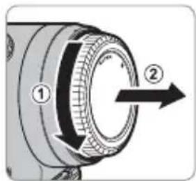
natural_image
Technical illustration of a mechanical component with an arrow indicating assembly or adjustment (no text or symbols present)natural_image
Technical illustration of a cylindrical mechanical component with internal slots and a handle (no text or symbols)De statiefgondel
Optical Image Stabilization (OIS)
AF-LOCK (scherpstelvergrendeling)
https://fujifilm-x.com/support/download/firmware/
SV-6 SVENSKA
Fästa axelremmen
natural_image
Technical illustration of a mechanical component with an arrow indicating a step, showing internal structure and assembly (no text or symbols)natural_image
Technical illustration of a cylindrical mechanical component with internal channels and a handle (no text or symbols)Stativkragen
AF-LOCK (Fokuslås)
https://fujifilm-x.com/support/download/firmware/
Feste skulderstroppen
Fjerne solblenderen
natural_image
Technical illustration of a mechanical component with an arrow indicating a step, showing internal structure (no text or symbols)natural_image
Technical illustration of a cylindrical mechanical component with internal channels and a handle (no text or symbols)Stativkrage
AF-LOCK (Fokuslås)
https://fujifilm-x.com/support/download/firmware/
Polarisaatiosuodin
natural_image
Technical illustration of a mechanical component with an arrow indicating a step, showing internal structure and assembly (no text or symbols)natural_image
Technical illustration of a cylindrical mechanical component with internal channels and a handle (no text or symbols)Jalustarengas
https://fujifilm-x.com/support/download/firmware/
Снятие бленды
natural_image
Technical illustration of a mechanical component with an arrow indicating a detail (no text or symbols present)natural_image
Technical illustration of a cylindrical connector with internal components and directional arrows (no text or symbols)Кольцо штатива
https://fujifilm-x.com/support/download/firmware/

IT-6 ITALIANO
natural_image
Technical illustration of a mechanical component with an arrow indicating a joint or connection (no text or symbols present)natural_image
Cross-sectional diagram of a cylindrical mechanical component with internal channels and a central valve (no text or symbols)La fl angia treppiedi
https://fujifilm-x.com/support/download/firmware/
natural_image
Technical illustration of a mechanical component with an arrow indicating assembly or adjustment (no text or symbols present)natural_image
Technical illustration of a cylindrical connector with internal slots and a handle (no text or symbols)Stativkraven
AF-LOCK (fokuslås)
PL-6 POLSKI
Zdejmowanie osłony
Filtr polaryzacyjny
natural_image
Technical illustration of a mechanical component with an arrow indicating a detail (no text or symbols present)natural_image
Technical illustration of a cylindrical connector with internal components (no text or symbols)Kołnierz statywu
AF-LOCK (blokada ostrości)
https://fujifilm-x.com/support/download/firmware/
安装肩带
如图所示将肩带安装至 2 个肩带穿孔。
取下遮光罩
偏光滤镜
natural_image
Mechanical assembly diagram showing a cylindrical component being inserted into a housing with a close-up view of the housing (no text or symbols present)随后,将手指插入操作端口即可旋转滤镜。
natural_image
Technical illustration of a cylindrical connector with internal slots and a handle (no text or symbols)三脚架固定环
AF-LOCK(对焦锁定)
https://fujifilm-x.com/support/download/firmware/
安装肩带
如圖所示將肩帶安裝至 2 個肩帶穿孔。
取下遮光罩
若要取下遮光罩,請按住遮光罩釋放栓扣並同時逆時針旋轉遮光罩。
偏光濾鏡
若要操作偏光濾鏡,請打開濾鏡操作埠蓋。

natural_image
Technical illustration of a mechanical component with an arrow indicating assembly or adjustment (no text or symbols present)隨後,將手指插入操作埠中即可旋轉濾鏡。
natural_image
Technical illustration of a cylindrical connector with internal slots and a handle (no text or symbols)三腳架固定環
拍攝對象。
AF-LOCK(對焦鎖定)
https://fujifilm-x.com/support/download/firmware/
KO-6
어깨 스트랩 부착
후드 제거
편광 필터
natural_image
Technical illustration of a mechanical component with an arrow indicating a detail (no text or symbols present)natural_image
Technical illustration of a cylindrical connector with internal slots and a handle (no text or symbols)삼각대 칼라
AF-LOCK(초점 고정)
.PRESET (b) feebtmeyr mcdd tskiyz

natural_image
Technical illustration of a mechanical component with an arrow indicating a step, showing no text or symbols.natural_image
Technical illustration of a cylindrical mechanical component with internal channels and a central lock (no text or symbols)تركيب الواقية
natural_image
Technical line drawing of a mechanical component with no visible text or symbols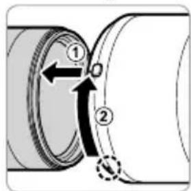
إزالةWOAQIY
عربي
AR-6
① واقية العدسة
② تحرير قفل الواقية
③ علامات التركيب