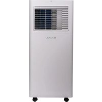
BC7KL24FWV2 - Air Conditioning Be Cool - Free user manual and instructions
Find the device manual for free BC7KL24FWV2 Be Cool in PDF.


| Product type | Monoblock mobile air conditioner |
| Brand | Be Cool |
| Model | BC7KL24FWV2 |
| Cooling capacity | 7,000 BTU/h (2.055 kW) |
| Power consumption (cooling) | 790 W |
| Supply voltage | 220-240 V ~ 50 Hz |
| Refrigerant | R290 (propane) |
| Sound level (acoustic power) | 65 dB(A) |
| Energy class | A |
| Airflow | 320 m³/h |
| Dimensions (W × H × D) | 290 × 675 × 280 mm |
| Net weight | 19.6 kg |
| Operating modes | Cooling, Dehumidification, Fan |
| Programmable timer | Yes (delayed start and stop) |
| Remote control | Yes (range 7 m, AAA 1.5 V batteries) |
| Air filter | Washable, weekly cleaning recommended |
| Condensate drainage | Manual or continuous (hose Ø 12.7 mm) |
| Safety | Automatic stop when tank full, compressor protection (restart after 3 min) |
| Warranty | 2 years (valid in Austria) |
| Supplied accessories | Exhaust hose, window adapter, window slider, remote control, drainage hose |
Frequently Asked Questions - BC7KL24FWV2 Be Cool
User questions about BC7KL24FWV2 Be Cool
0 question about this device. Answer the ones you know or ask your own.
Ask a new question about this device
Download the instructions for your Air Conditioning in PDF format for free! Find your manual BC7KL24FWV2 - Be Cool and take your electronic device back in hand. On this page are published all the documents necessary for the use of your device. BC7KL24FWV2 by Be Cool.
USER MANUAL BC7KL24FWV2 Be Cool
natural_image
Exterior view of a white industrial air conditioner unit with ventilation grille and 'BE COOL' branding (no other text or symbols visible)HERZLICHEN GLÜCKWUNSCH!
natural_image
Line drawings of various electronic devices including a coiled tube, ring, and control panel (no text or symbols)natural_image
Diagram showing a bolt and a cylindrical component with a curved arrow indicating rotation (no text or symbols)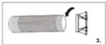
natural_image
Diagram of a cylindrical object with a curved arrow pointing to a triangular structure, labeled '3.' (no text or symbols on the diagram itself)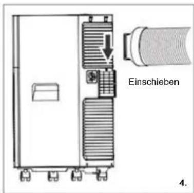
natural_image
Interior view of a room with a white hose and a small electronic device, overlooking a window with trees and greenery (no visible text or symbols)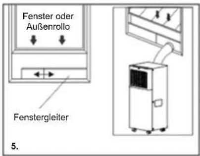
natural_image
Diagram of a vacuum cleaner emitting exhaust pipes, with no text or symbols presentnatural_image
Line drawing of hands holding a mobile phone with an arrow indicating the device (no text or symbols present)Symbolbild
natural_image
Simple line drawing of a vertical stacker with a checkmark symbol (no text or labels)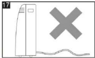
natural_image
Simple line drawing of a tower with a cross symbol above it, no text or labels presentREINIGUNG
natural_image
Diagram of a portable air conditioner unit with cooling fan and mounting base (no text or symbols)BE COOL
MANUEL D'INSTRUCTION
Climatiseur mobile BC7KL24FWV2
natural_image
White industrial air conditioner unit with ventilation grille and 'BE COOL' branding (no other text or symbols visible)FÉLICITATIONS! MERCI D'AVOIR CHOISI UN PRODUIT DE BE COOL.
BE COOL


VEUILLEZ LIRE ATTENTIVEMENT LE MODE D'EMPLOI AVANT DE COMMENCER L'ASSEMBLAGE, L'INSTALLATION, LE FONCTIONNEMENT OU L'ENTRETIEN. PROTÉGEZ-VOUS ET PROTÉGEZ LES AUTRES EN RESPECTANT LES CONSIGNES DE SÉCURITÉ. LE NON-RESPECT DES INSTRUCTIONS PEUT ENTRAÎNER DES BLESSURES CORPORELLES ET/OU DES DOMMAGES MATÉRIELS ET/OU LA PERTE DE LA COUVERTURE DE LA GARANTIE !
INFORMATIONS IMPORTANTES CONCERNANT LA SÉCURITÉ, L'EMPLACEMENT ET LE BRANCHEMENT ÉLECTRIQUE.
natural_image
Line drawings of various remote control devices including a coiled tube, lens, and camera (no text or symbols)natural_image
Simple line drawing of a cylindrical object with a separate inset showing a curved arrow (no text or symbols)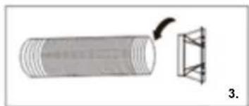
natural_image
Diagram of a cylindrical object with a separate triangular structure, labeled '3.' (no text or symbols on the object itself)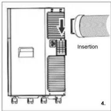
natural_image
Interior view of a room with a white hose and wooden box, overlooking a window with trees and a fence in the background (no visible text or symbols)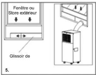
natural_image
Diagram of a device connected to a pipe with a diagonal line crossing through it (no text or symbols present)PANNEAU DE CONTRÔLE ET TÉLÉCOMMANDE
natural_image
Illustration of hands holding a mobile phone with an arrow indicating the device (no text or symbols present)Image du symbole
natural_image
Simple line drawing of a vertical stacker with a checkmark overlay (no text or symbols)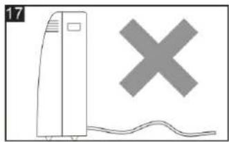
natural_image
Simple line drawing of a tower with a cross symbol above it, no text or labels presentNETTOYAGE
natural_image
Diagram of a portable air conditioner unit with cooling fan and wheels, showing a small component inserted (no text or symbols)BE COOL
natural_image
White industrial air conditioner unit with ventilation grille and 'BE COOL' branding (no other text or symbols visible)CONGRATULAZIONI! GRAZIE PER AVER SCELTO UN PRODOTTO BE COOL.
BE COOL


LEGGERE ATTENTAMENTE LE ISTRUZIONI PER L'USO PRIMA DI INIZIARE IL MONTAGGIO, L'INSTALLAZIONE, IL FUNZIONAMENTO O LA MANUTENZIONE. PROTEGGERE SE STESSI E GLI ALTRI SEGUENDO LE ISTRUZIONI DI SICUREZZA. LA MANCATA OSSERVANZA DELLE ISTRUZIONI PUÒ CAUSARE LESIONI PERSONALI E/O DANNI MATERIALI E/O LA PERDITA DELLA COPERTURA DELLA GARANZIA!
IMPORTANTI INFORMAZIONI SULLA SICUREZZA, L'UBICAZIONE E IL COLLEGAMENTO ELETTRICO.
natural_image
Line drawings of various remote control devices including a coiled tube, ring, and remote control panel (no text or symbols)natural_image
Diagram showing a mechanical component with a curved arrow indicating rotation (no text or symbols)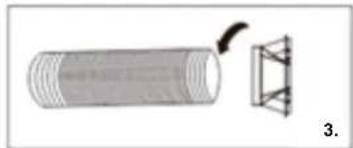
natural_image
Diagram showing a cylindrical object with a curved arrow pointing to a triangular structure, labeled '3.' (no text or symbols on the diagram itself)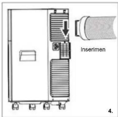
natural_image
Interior view of a room with a white hose and a small device, overlooking a window with trees and a fence in the background (no visible text or symbols)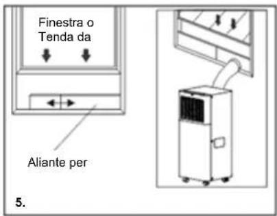
natural_image
Diagram of a vehicle with a curved ramp and diagonal line crossing (no text or symbols)PANNELLO DI CONTROLLO E TELECOMANDO
ACCENSIONE DEL DISPOSITIVO
natural_image
Line drawing of hands holding a mobile phone with an arrow indicating the right-hand side (no text or symbols present)Immagine simbolo
natural_image
Simple line drawing of a vertical stacker with a checkmark overlay (no text or symbols)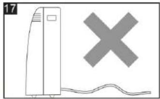
natural_image
Simple line drawing of a tower with a cross symbol and wavy base (no text or labels)PULIZIA
natural_image
Line drawing of a portable air conditioner unit with cooling fan and wheels (no text or symbols)BE COOL
RICERCA MANCANTE
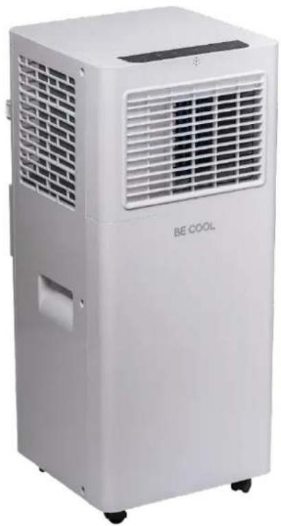
Mobiele airconditioner BC7KL24FWV2
natural_image
White industrial air conditioner unit with ventilation grille and 'BE COOL' branding (no other text or symbols visible)GEFELICITEERD!
BEDANKT VOOR HET KIEZEN VAN EEN PRODUCT VAN BE COOL.
BE COOL


LEES DE BEDIENINGSINSTRUCTIES ZORGVULDIG DOOR VOORDAT U BEGINT MET DE MONTAGE, INSTALLATIE, BEDIENING OF HET ONDERHOUD. BESCHERM UZELF EN ANDEREN DOOR DE VEILIGHEIDSINSTRUCTIES OP TE VOLGEN. HET NIET OPVOLGEN VAN DE INSTRUCTIES KAN LEIDEN TOT PERSOONLIJK LETSEL EN/OF MATERIËLE SCHADE EN/OF VERLIES VAN DE GARANTIEDEKKING!
BELANGRIJKE INFORMATIE OVER VEILIGHEID, LOCATIE EN ELEKTRISCHE AANSLUITING.



natural_image
Line drawings of various remote control devices including a coiled tube, lens, and remote control panel (no text or symbols)natural_image
Simple line drawing of a cylindrical object with a circular inset, no text or symbols present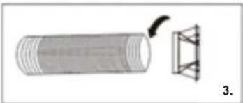
natural_image
Diagram of a cylindrical object with a curved arrow pointing to a triangular structure, labeled '3.' (no text or symbols on the diagram itself)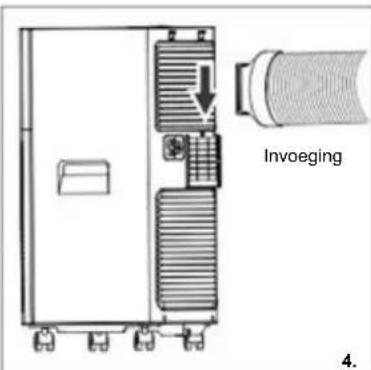
natural_image
Black-and-white photo of a window with a white hose and cloth, overlooking a garden (no text or symbols visible)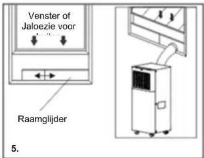
natural_image
Diagram showing a vehicle with a diagonal line crossing a curved road, no text or symbols presentBEDIENINGSPANEELE EN AFSTANDSBEDIENING
- timertoets
- ventilatorknop
- toets verhogen
- display
- "Verlagen" toets
- modusknop
- AAN/UIT-knop
HET APPARAAT INSCHAKELEN
natural_image
Line drawing of hands inserting a mobile phone into a device (no text or symbols)Symbool afbeelding
BE COOL
natural_image
Simple line drawing of a vertical stacker with a checkmark symbol (no text or labels)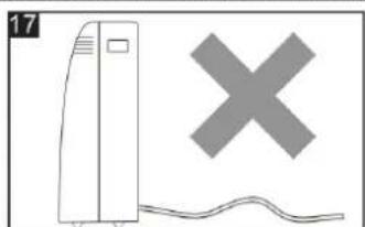
natural_image
Simple line drawing of a tower with a cross symbol and a wavy line below (no text or labels)BE COOL
SCHOONMAKEN
natural_image
Diagram of a portable air conditioner unit with cooling fan and base, no visible text or symbolsBE COOL
MISSING ZOEKEN
natural_image
White portable air conditioner unit with ventilation grille and 'BE COOL' branding (no other text or symbols visible)¡ENHORABUENA!
GRACIAS POR ELEGIR UN PRODUCTO DE BE COOL.
BE COOL


natural_image
Line drawings of various household appliances including a coiled tube, hand tools, and a control panel (no text or symbols)1x manguera de escape
1x adaptador de ventana
1x adaptador de manguera de escape
natural_image
Diagram showing a mechanical component with a rotating shaft and a flanged housing (no text or symbols)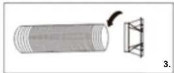
natural_image
Diagram showing a cylindrical object with a curved arrow pointing to a triangular structure, labeled '3.' (no text or symbols on the diagram itself)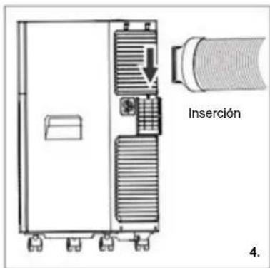

natural_image
Interior view of a room with a large white hose hanging from a window, overlooking trees and a distant structure (no visible text or symbols)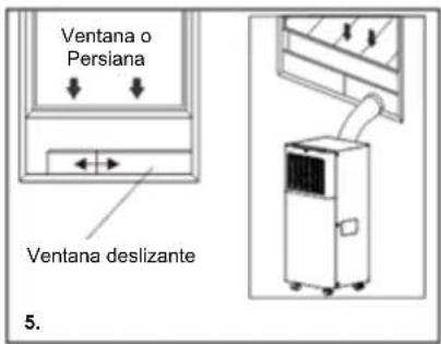
natural_image
Diagram showing a device with a diagonal line crossing over a curved pipe or duct, no text or symbols present.PANEL DE CONTROL Y MANDO A DISTANCIA
natural_image
Line drawing of hands holding a mobile phone with an arrow indicating the device (no text or symbols present)Imagen del símbolo
natural_image
Illustration of a vertical air conditioner unit with a checkmark symbol (no text or labels)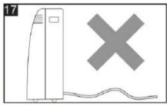
natural_image
Simple line drawing of a tower with a cross symbol and wavy base (no text or labels)LIMPIEZA
natural_image
White industrial air purifier unit with ventilation grille and 'BE COOL' branding (no other text or symbols visible)GRATULUJEME!
DĚKUJEME, ŽE JSTE SI VYBRALI PRODUKT OD SPOLEČNOSTI BE COOL.
BE COOL


PŘED ZAHÁJENÍM MONTÁŽE, INSTALACE, PROVOZU NEBO ÚDRŽBY SI POZORNĚ PŘEČTĚTE NÁVOD K OBSLUZE. DODRŽOVÁNÍM BEZPEČNOSTNÍCH POKYNŮ CHRAŇTE SEBE I OSTATNÍ. NEDODRŽENÍ POKYNŮ MŮŽE MÍT ZA NÁSLEDEK ZRANĚNÍ OSOB A/NEBO POŠKOZENÍ MAJETKU A/NEBO ZTRÁTU ZÁRUKY!
DÜLEŽITÉ INFORMACE O BEZPEČNOSTI, UMÍSTĚNÍ A ELEKTRICKÉM PŘIPOJENÍ.
natural_image
Line drawings of various household appliances including a coiled tube, ring-shaped device, and control panel (no text or symbols)natural_image
Simple diagram showing a cylindrical object being dropped with a curved arrow, no text or symbols present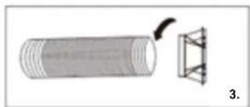
natural_image
Diagram showing a cylindrical object with a curved arrow pointing to a triangular structure, labeled '3.' (no text or symbols on the diagram itself)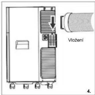
natural_image
Interior view of a room with a white hose and a small electronic device, overlooking a window with trees and a distant tree (no text or symbols visible)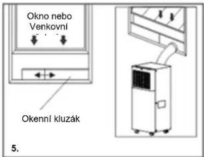
natural_image
Diagram showing a vehicle with a curved ramp and a diagonal line intersecting it, alongside a shaded rectangular area (no text or symbols)OVLÁDACÍ PANEL A DÁLKOVÉ OVLÁDÁNÍ
ZMĚNA JEDNOTKY TEPLOTY
natural_image
Simple line drawing of a vertical stacker with a checkmark symbol (no text or labels)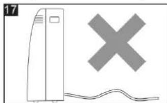
natural_image
Simple line drawing of a server unit and a cross symbol (no text or labels)ČIŠTĚNÍ
natural_image
Diagram of a portable air conditioner unit with cooling fan and mounting bracket (no text or symbols)natural_image
Exterior view of a white BE COOL air conditioner unit with ventilation grille and wheels (no visible text or symbols on the device body)GRATULUJEME! ĐAKUJEME, ŽE STE SI VYBRALI PRODUKT OD SPOLOČNOSTI BE COOL.
BE COOL


PRED ZAČATÍM MONTÁŽE, INŠTALÁCIE, PREVÁDZKY ALEBO ÚDRŽBY SI POZORNE PREČÍTAJTE NÁVOD NA OBSLUHU. DODRŽIAVANÍM BEZPEČNOSTNÝCH POKYNOV CHRÁŇTE SEBA AJ OSTATNÝCH. NEDODRŽANIE POKYNOV MÔŽE MAŤ ZA NÁSLEDOK ZRANENIE OSÔB A/ALEBO POŠKODENIE MAJETKU A/ALEBO STRATU ZÁRUČNÉHO KRYTIA!
DÔLEŽITÉ INFORMÁCIE O BEZPEČNOSTI, UMIESTNENÍ A ELEKTRICKOM PRIPOJENÍ.
natural_image
Line drawings of various household appliances including a coiled tube, a wrist strap, and a remote control panel (no text or symbols)natural_image
Simple diagram showing a mechanical component with a curved arrow indicating rotation (no text or symbols)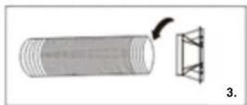
natural_image
Diagram showing a cylindrical object with a curved arrow pointing to a triangular structure, labeled '3.' (no text or symbols on the diagram itself)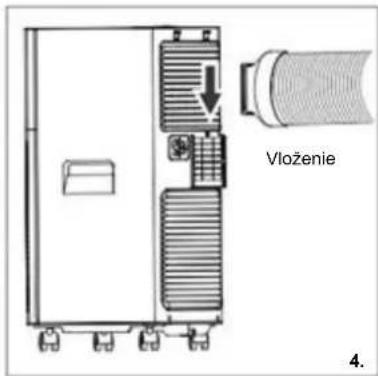
natural_image
Interior view of a room with a large white hose and window, showing outdoor trees and a small device (no text or symbols visible)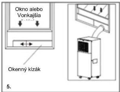
Montáž vodiacich líšt okien
Krok 1: Materialy
A) Hlavný panel
B) Doska s otvorom
C) Skrutka/kolík
Krok 2: Montáž
natural_image
Diagram of a vacuum cleaner with a curved duct and diagonal line crossing it (no text or symbols)OVLÁDACÍ PANEL A DIAL'KOVÉ OVLÁDANIE
ZMENA JEDNOTKY TEPLOTY
natural_image
Line drawing of hands holding a mobile phone with an arrow indicating the device (no text or symbols present)Obrázok symbolu
natural_image
Simple line drawing of a vertical stacker with a checkmark symbol (no text or labels)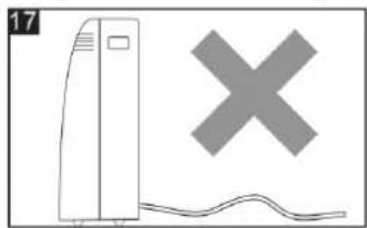
natural_image
Illustration of a server unit and a cross symbol (no text or labels)ČISTENIE
Pred čistením alebo údržbou prístroja ho vypnite stlačením tlačidla na ovládacom paneli alebo dial'kovom ovládači, počkajte niekol'ko minút a potom odpojte napájací kábel zo zásuvky.
Čistenie puzdra
Kryt zariadenia vyčistite mierne navlhčenou handričkou a potom ho dôkladne vysušte suchou handričkou.
MANUAL DE INSTRUCTIUNI
natural_image
White industrial air conditioner unit with ventilation grille and 'BE COOL' branding (no other text or symbols visible)FELICITĂRI!
VĂ MULTUMIM CĂ AȚI ALES UN PRODUS BE COOL.

VĂ RUGĂM SĂ CITIȚI CU ATENTIE INSTRUCTIUNILE DE UTILIZARE ÎNAINTE DE A ÎNCEPĂ ASAMBLAREA, INSTALAREA, FUNCTIONAREA SAU ÎNTRETINEREA. PROTEJAȚI-VĂ PE DUMNEAVOASTRĂ ȘI PE CEILALȚI RESPECTÂND INSTRUCTIUNILE DE SIGURANTĂ. NERESPECTAREA INSTRUCTIUNILOR AR PÚTEA DUCE LA VĂTĂMĂRI CORPORALE ȘI/SAU DAUNE MATERIALE ȘI/SAU PIERDEREA ACOPERIRII GARANTIEI!
INFORMATII IMPORTANTE PRIVIND SIGURANTA, AMPLASAREA ŞI CONECTAREA ELECTRICĂ.

natural_image
Line drawings of various remote control devices including a coiled tube, lens, and remote control panel (no text or symbols)natural_image
Interior view of a room with a white hose and a wall-mounted device, overlooking a window with trees and distant plants (no visible text or symbols)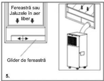
natural_image
Diagram of a device with a curved pipe and intersecting lines, no text or symbols presentPANOU DE CONTROL ŞI TELECOMANDĂ
natural_image
Illustration of hands holding a mobile phone with an arrow indicating the device (no text or symbols present)Imagine simbolică
natural_image
Simple line drawing of a vertical stacker with a checkmark symbol (no text or labels)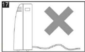
natural_image
Simple line drawing of a tower with a cross symbol above it, no text or labels presentCURĂȚARE
natural_image
Line drawing of a portable air conditioner unit with a small hand holding a small object underneath (no text or symbols)BE COOL
CĂUTAREA DISPĂRUTĂ
natural_image
Exterior view of a white industrial air conditioner unit with ventilation grille and 'BE COOL' branding (no other text or symbols visible)GRATULACJE! DZIEKUJEMY ZA WYBRANIE PRODUKTU OD BE COOL.
BE COOL


PRZED ROZPOCZĘCIEM MONTAŻU, INSTALACJI, OBSŁUGI LUB KONSERWACJI NALEŻY UWAŻNIE PRZECZYTAĆ INSTRUKCJĘ OBSŁUGI. NALEŻY CHRONIĆ SIEBIE I INNYCH, POSTĘPUJĄC ZGODNIE Z INSTRUKCJAMI BEZPIECZEŃSTWA. NIEPRZESTRZEGANIE INSTRUKCJI MOŻE SKUTKOWAĆ OBRAŻENIAMI CIAŁA I/LUB USZKODZENIEM MIENIA I/LUB UTRATĄ GWARANCJI!
WAŻNE INFORMACJE DOTYCZĄCE BEZPIECZEŃSTWA, LOKALIZACJI I PODŁĄCZENIA ELEKTRYCZNEGO.
natural_image
Line drawings of various household appliances including a coiled tube, ring-shaped device, and control panel (no text or symbols)natural_image
Simple line drawing of a cylindrical object with a separate inset showing a ring and a curved arrow (no text or symbols)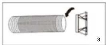
natural_image
Diagram showing a cylindrical object with a curved arrow pointing to a triangular structure, labeled '3.' (no text or symbols on the diagram itself)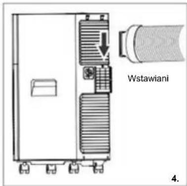
natural_image
Interior view of a room with a white hose and a small device on the floor, overlooking a window with trees and a fence in the background (no visible text or symbols)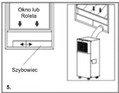
natural_image
Diagram of a vacuum cleaner emitting exhaust pipes, with no text or symbols presentnatural_image
Line drawing of hands holding a mobile phone with an arrow indicating the right-hand rule (no text or symbols present)Obraz symbolu
natural_image
Simple line drawing of a vertical stacker with a checkmark symbol (no text or labels)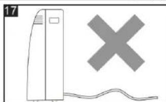
natural_image
Simple line drawing of a tower with a cross symbol and wavy base (no text or labels)BE COOL
CZYSZCZENIE
natural_image
Line drawing of a portable air conditioner unit with cooling fan and base mount (no text or symbols)natural_image
Exterior view of a white industrial air conditioner unit with ventilation grille and 'BE COOL' branding (no other text or symbols visible)ČESTITAMO! HVALA, KER STE IZBRALI IZDELEK BE COOL.
BE COOL


Aktualna navodila za uporabo in drugi jeziki
PRED ZAČETKOM MONTAŽE, NAMESTITVE, DELOVANJA ALI VZDRŽEVANJA NATANČNO PREBERITE NAVODILA ZA UPORABO. Z UPOŠTEVANJEM VARNOSTNIH NAVODIL ZAŠČITITE SEBE IN DRUGE. NEUPOŠTEVANJE NAVODIL LAHKO POVZROČI TELESNE POŠKODBE IN/ALI MATERIALNO ŠKODO IN/ALI IZGUBO GARANCIJSKEGA KRITJA!
POMEMBNE INFORMACIJE O VARNOSTI, LOKACIJI IN ELEKTRIČNEM PRIKLJUČKU.

natural_image
Line drawings of various home appliances including a coiled tube, wrist strap, and control panel (no text or symbols)natural_image
Simple diagram showing a mechanical component with a rotating arrow and a cylindrical body, labeled '2.' (no text or symbols on the diagram itself)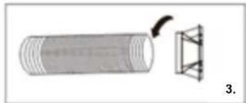
natural_image
Diagram of a cylindrical object with a curved arrow pointing to a triangular structure, labeled '3.' (no text or symbols on the diagram itself)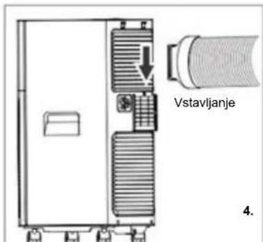
natural_image
Interior view of a room with a white hose and wooden box, overlooking a window with trees and a distant tree (no text or symbols visible)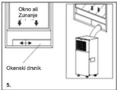
Vgradnja okenskih vodil
Korak 1: Materiali
natural_image
Diagram of a mechanical device with a curved pipe and diagonal line crossing (no text or symbols)NADZORNA PLOŠČA IN DALJINSKI UPRAVLJALNIK
natural_image
Simple line drawing of a vertical stacker with a checkmark symbol (no text or labels)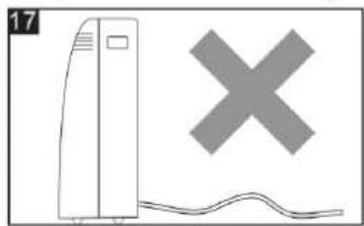
natural_image
Illustration of a server unit and a cross symbol (no text or labels)ČIŠČENJE
S sesalnikom odstranite prah, ki se je nabral na filtru. Če
natural_image
Line drawing of a portable air conditioner unit with cooling fan and wheels (no text or symbols)natural_image
White industrial air conditioner unit with ventilation grille and 'BE COOL' branding (no other text or symbols visible)ČESTITAMO!
HVALA VAM ŠTO STE ODABRALI PROIZVOD IZ BE COOL.
BE COOL


Aktualne upute za uporabu i drugi jezici
Preuzmite najnovije upute za uporabu na raznim jezicima putem poveznice www.schuss-home.at/downloads ili skenirajte prikazani QR kod. Slijedite upute na web stranici.

MOLIMO VAS, PAŽLJIVO PROČITAJTE UPUTE ZA UPOTREBU PRIJE POČETKA SASTAVLJANJA, INSTALACIJE, RADA ILI ODRŽAVANJA. ZAŠTITITE SEBE I DRUGE PRIDRŽAVANJEM SIGURNOSNIH UPUTA. NEPRIDRŽAVANJE UPUTA MOŽE REZULTIRATI OSOBNIM OZLJEDAMA I/ILI ŠTETOM IMOVINE I/ILI GUBITKOM POKRIVANJA JAMSTVA!
VAŽNE INFORMACIJE O SIGURNOSTI, LOKACIJI I ELEKTRIČNOM POVEZIVANJU.

- Prije uporabe uređaja pažljivo pročitajte sve upute.
- Koristite ovaj uređaj samo u skladu sa smjernicama u uputama za uporabu. Svaka druga uporaba koju proizvođač ne preporučuje može rezultirati požarom, strujnim udarom ili ozljedama.
- Ovaj uređaj je namijenjen isključivo za klimatizaciju kućnih stambenih prostora i ne smije se koristiti ni u koju drugu svrhu.
- Uređaj nije prikladan za kontinuirani i precizan rad i također se ne bi trebao koristiti za hlađenje električnih sustava (npr.: u serverskim sobama).
- Zabranjeno je prilagođavati ili modificirati karakteristike ovog uređaja na bilo koji način i koristiti samo rezervne dijelove i dodatnu opremu preporučenu od strane proizvođača (u protivnom će poništiti jamstvo i jamstvo).
- Uvijek i samo kontaktirajte centre za korisničku podršku ovlaštene od strane proizvođača za bilo kakve popravke uređaja, utikača ili kabela. Centre za korisničku podršku možete pronaći online na www.becool.at.
- Uklonite ambalažu i provjerite da klima uređaj nije oštećen. Ako ste u nedoumici, nemojte koristiti klima uređaj i obratite se servisnom centru ili svom prodavaču.
- Držite djecu podalje od materijala za pakiranje. Opasnost od gušenja ako se proguta!
BE COOL
natural_image
Line drawings of various household appliances including a coiled tube, ring-shaped device, and control panel (no text or symbols)1x ispušno crijevo
1x adapter za prozore
1x adapter za ispušno crijevo
1x prozorska klizaljka
1x daljinski upravljač
1x odvodno crijevo
BE COOL
OBAVIJEST:
Sve ilustracije u ovom priručniku služe samo u ilustrativne svrhe. Vaš uređaj može izgledati malo drugačije.
Prije uporabe provjerite jesu li sav pribor uklonjen iz pakiranja.
MONTAŽA I MONTAŽA
Ispušni zrak
natural_image
Simple diagram showing a cylindrical object being cut with a curved arrow, no text or symbols present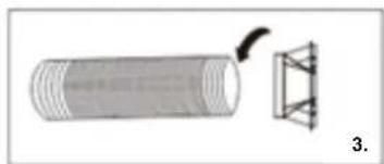
natural_image
Diagram showing a cylindrical object with a curved arrow pointing to a triangular structure, labeled '3.' (no text or symbols on the diagram itself)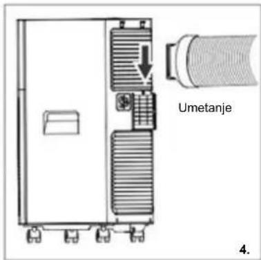
BE COOL
PREPORUKA OD BE COOL
Preporučamo SHE Hot-Air Stop kod postavljanja na prozore, balkonska vrata ili klizna vrata.
One nude sljedeće prednosti:
- Topli zrak ne struji u životni prostor →stoga štedi energiju
• Jednostavna i brza montaža - Izdržljiv, vodootporan materijal
- Moguće otvaranje i zatvaranje
- Perivo
Dostupno od vašeg dobavljača klima uređaja.
natural_image
Black-and-white photo of a person hanging from a window with a white hose, near a wall and trees (no text or symbols visible)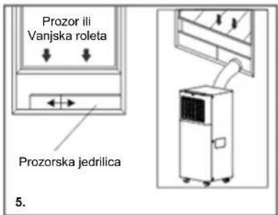
Ugradnja prozorskih vodilica
Korak 1: Materijali
A) Glavna ploča
B) Ploča s rupom
C) Vijak/zatik
Korak 2: Sastavljanje
natural_image
Diagram of a vehicle with a curved pipe and diagonal line crossing (no text or symbols)UPRAVLJAČKA PLOČA I DALJINSKI UPRAVLJAČ
-
tipka mjerača vremena
-
gumb ventilatora
-
tipka za povećanje
-
prikaz
-
Tipka "Smanjenje".
-
gumb za način rada
-
Tipka ON/OFF
A. Indikator hlađenja
B. Indikator odvlaživanja
C. Indikator ventilatora
OBAVIJEST:
natural_image
Illustration of a vertical air conditioner unit with a checkmark symbol (no text or labels)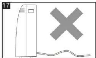
natural_image
Simple line drawing of a server tower with a gray X symbol above it, no text or symbols present.ČIŠĆENJE
Prije čišćenja ili servisiranja jedinice isključite je pritiskom na tipku na upravljačkoj ploči ili daljinskom upravljaču, pričekajte nekoliko minuta, a zatim izvucite kabel za napajanje iz zidne utičnice.
Čišćenje kućišta
Očistite kućište uređaja lagano vlažnom krpom, a zatim ga temeljito osušite suhom krpom.
natural_image
Line drawing of a portable air conditioner unit with cooling fan and battery (no text or symbols)natural_image
Exterior view of a white industrial air conditioner unit with ventilation grille and 'BE COOL' branding (no other text or symbols visible)CONGRATULATIONS! THANK YOU FOR CHOOSING A PRODUCT FROM BE COOL.
BE COOL


Current operating instructions and other languages
Download the latest operating instructions in various languages via the link www.schuss-home.at/downloads or scan the QR code shown. Follow the instructions on the website.

PLEASE READ THE OPERATING INSTRUCTIONS CAREFULLY BEFORE STARTING ASSEMBLY, INSTALLATION, OPERATION OR MAINTENANCE. PROTECT YOURSELF AND OTHERS BY FOLLOWING THE SAFETY INSTRUCTIONS. FAILURE TO FOLLOW INSTRUCTIONS COULD RESULT IN PERSONAL INJURY AND/OR PROPERTY DAMAGE AND/OR LOSS OF WARRANTY COVERAGE!
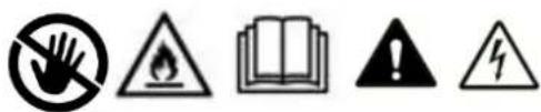
IMPORTANT SAFETY, LOCATION AND ELECTRICAL CONNECTION INFORMATION.

- Please read all instructions carefully before using the device.
- Only use this device in accordance with the guidelines in the operating instructions. Any other use not recommended by the manufacturer could result in fire, electric shock or personal injury.
- This appliance is intended exclusively for air-conditioning of domestic living spaces and must not be used for any other purpose.
- The device is not suitable for continuous and precision operation and should also not be used for cooling electrical systems (e.g.: in server rooms).
- It is forbidden to adapt or modify the characteristics of this device in any way and use only spare parts and accessories recommended by the manufacturer (failure to do so will void the warranty and guarantee).
- Always and only contact customer service centers authorized by the manufacturer for any repairs to the device, power plug or cable. You can find the customer service centers online at www.becool.at.
BE COOL
-
Remove the packaging and make sure that the air conditioner is not damaged. If in doubt, do not use the air conditioner and contact the service center or your dealer.
-
Keep children away from packaging material. Danger of suffocation if swallowed!
-
If the power supply cable is damaged, it must be replaced by the manufacturer or an authorized service center to avoid all possible risks.
-
The device must be installed in accordance with local installation and operating regulations for electrical systems.
-
The electrical socket in which you connect the device must not be defective or loose and must be suitable for the required current load and, above all, reliably grounded. If in doubt, have your electrical installation checked by a qualified electrician.
-
Before connecting to the mains, you must check that the type of current and mains voltage correspond to the specifications on the device type plate located on the rear.
-
Avoid using an extension cord, as it could overheat and cause a fire.
-
Do not twist or kink the power cord.
-
This device may only be used by adults.
-
Children under 8 years of age and persons with reduced physical, mental, sensory or spiritual capabilities or lack of experience and knowledge should not use this appliance unless they have been given supervision or instruction concerning use of the appliance in a safe way and understand the hazards involved.
-
Do not let children play with the packaging and also make sure that children do not play with the device.
-
Do not use the air conditioner outdoors.
-
Do not use the device with wet hands.
-
Never operate the device in rooms where gas, oil or sulfur are present.
-
Do not place the device near heat sources (e.g.: next to heating systems and gas heaters) and avoid direct sunlight.
-
Keep a minimum distance of at least 50cm from flammable substances (e.g. alcohol, etc.) or pressurized vessels (e.g. spray containers).
-
Do not use the air conditioner near water or high humidity, e.g. in a damp basement, next to a swimming pool, bathtub or shower. Make sure that no water enters the unit.
-
Do not place heavy or hot objects on the device and never cover the device.
-
Never insert fingers, pens or other objects into the device and make sure that the air inlet and outlet are never blocked.
-
Always switch off the device before disconnecting the power plug.
-
Do not pull on the power cord to disconnect the device from the mains power. Always pull on the plug to unplug the power cord. Do not handle the plug with wet hands to avoid electric shock.
-
Unplug the unit when not in use, before cleaning, servicing, or moving from one location to another.
BE COOL
- If the device has a defect, switch it off with the On/Off key on the control panel and contact the customer hotline.
- Keep the air conditioner in good condition by maintaining and cleaning the unit.
- The air filter must be cleaned at least once a week.
- Store the device vertically in a safe, dry place inaccessible to children when not in use. Do not cover the device with plastic packaging.
- Store the device in a room without operating ignition sources (e.g. open fire, an operating gas appliance or an electric heater with an open heat source).
- The air conditioner is to be transported in an upright position or slightly on its side. Empty the internal condensation water tank beforehand. Wait at least one hour after transporting the unit before switching it on.
- Always and only contact service centers authorized by the manufacturer for any repairs to the device, power plug or cable.
- Do not use any means to accelerate or eliminate the defrosting process, the device will do it by itself.
- If you have any questions about maintenance, you can contact the customer hotline/service center authorized by the manufacturer.
WARNING
The main switch and the On/Off switch should not be used as the sole means of disconnecting power. Always unplug the power cord before starting maintenance or moving the unit.
To avoid the risk of electric shock, unplug the uni from the wall outlet when not in use - also before any cleaning.
BE COOL
SPECIFIC INFORMATION ON REFRIGERANT R290
-
R290 is a refrigerant in accordance with EC environmental specifications.
-
The refrigerant is odorless.
-
The device must be installed in a room where there are no ignition sources in operation (e.g.: open fire, gas and electric devices in operation with open heat source).
-
You must not perforate or burn the air conditioner.
-
Care must be taken not to drill into the cooling circuit.
-
Non-ventilated spaces where the unit is installed, operated or stored must be constructed so that any refrigerant leaks do not accumulate. This will prevent fire or explosion hazards caused by ignition of the refrigerant by electric stoves, stoves or other sources of ignition.
-
The device must be stored in such a way that no mechanical damage can occur.
-
The persons working on or performing interventions on a refrigeration circuit must be in possession of a valid certificate issued by an authorized authority, certifying their expertise with regard to the handling of refrigerants through an evaluation specification recognized by the industry associations.
-
Repairs must be carried out in accordance with the instructions provided by the manufacturer of the unit. Repair and maintenance operations that require the use of additional specialized personnel must be carried out under the supervision of the specialist responsible for handling flammable refrigerants.
BE COOL
Recycling, disposal, declaration of conformity
 | RECYCLINGThe packaging materials can be recycled. It is therefore recommended to dispose of them in sorted waste |
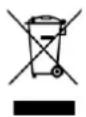 | DISPOSALThe "crossed-out dustbin" symbol requires the separate disposal of waste electrical and electronic equipment (WEEE). Electrical and electronic equipment may contain hazardous and environmentally harmful substances. Therefore, do not dispose of them in unsorted residual waste, but at a designated collection point for waste electrical and electronic equipment. This will help to protect resources and the environment. For further information, please contact your dealer or the local authorities. Directive 2012/19/EU |
 | BATTERY DISPOSALIn accordance with current legislation regarding batteries, accumulators, and related waste, the symbol of the crossed-out bin on the battery indicates that it is prohibited to dispose of used batteries in household waste. Batteries and accumulators contain highly polluting substances. The user is obliged to dispose of used batteries at designated collection points in the municipality or in the appropriate containers. This service is free of charge. In this way, legal requirements are met and the environment is protected.These symbols can be found on batteries:Li = Battery contains lithiumAl = Battery contains alkaliMn = Battery contains manganeseCR 2025 (Li); AA (Al, Mn); AAA (Al, Mn) |
 | DECLARATION OF CONFORMITYWe hereby confirm that this product complies with the essential requirements, regulations and directives of the EU. You can view the detailed declaration of conformity at any time under the following link:https://www.schuss-home.at/downloads |
Errors and technical changes excepted.
BE COOL
DESCRIPTION OF THE DEVICE AND SCOPE OF DELIVERY
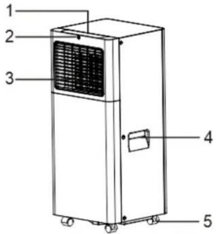
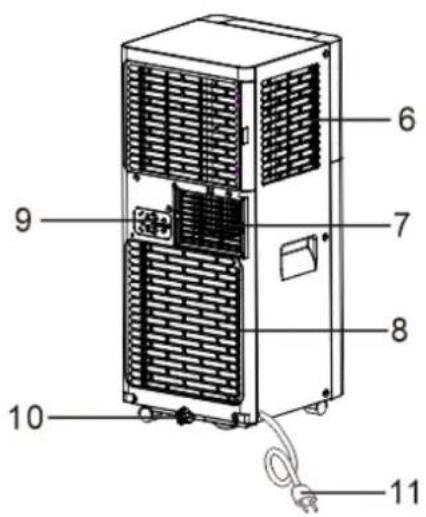
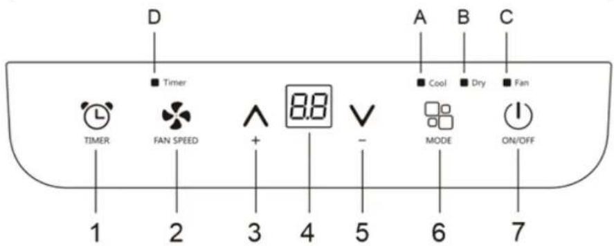
- Control panel
- Remote control receiver
- Control panel
- Handle (Both sides)
- Rollers
-
Intake grille
-
Exhaust air outlet
- Intake grille
- Steckerficierer
- Drain for codens water
- Power cable
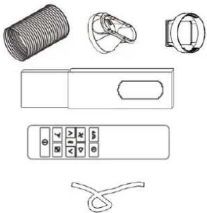
Scope of delivery
natural_image
Line drawings of various household appliances including a coiled tube, ring-shaped device, and control panel (no text or symbols)1x exhaust hose
1x window adapter
1x exhaust hose adapter
1x window glider
1x remote control
1x drain hose
BE COOL
NOTICE:
All illustrations in this manual are for illustrative purposes only. Your device may look slightly different.
Make sure that all accessories have been removed from the packaging before use.
ASSEMBLY AND INSTALLATION
Exhaust air
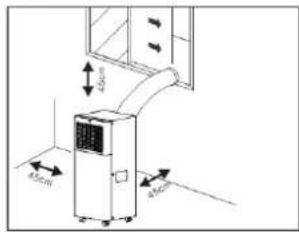
In cooling mode, the unit should be placed near a window or opening to exhaust the warm exhaust air to the outside. Start by placing the unit on a flat surface and make sure there is a minimum distance of 45 cm (18 inches) all around. There should also be an electrical outlet nearby.
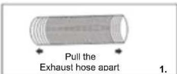
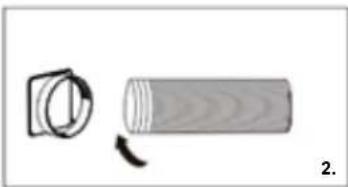
Take one side of the hose and extend it (see Figure 1), then screw it to the hose inlet (see Figure 2).
Extend the other side of the hose and attach it to the hose outlet (see Figure 3).
Install the hose connector on the unit (see Figure 4).
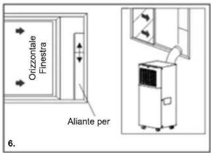
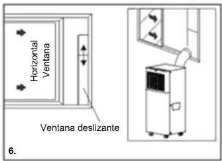
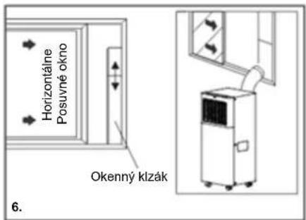
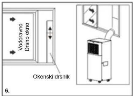
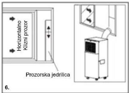
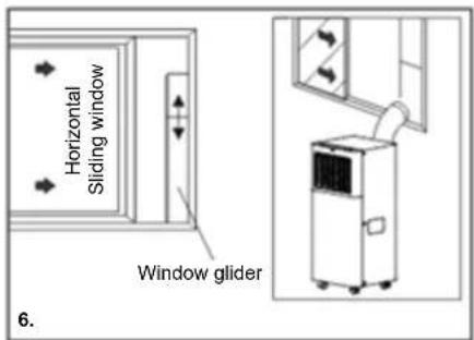
Attach the hose outlet to the window slide set and ensure an airtight connection (see Figure 5 & 6).
This ensures that the mobile air conditioner works efficiently and that the discharged warm air is properly directed outside.
Your window glider kit is designed for most vertical and horizontal window applications, but can also be used with exterior blinds.
However, certain types of windows may require you to change some aspects of the installation procedures. The window slider kit can be fixed with screws.
NOTICE:
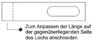
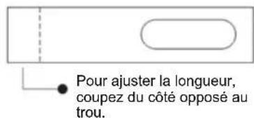
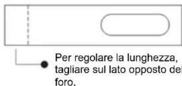
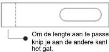
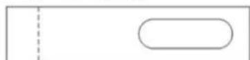
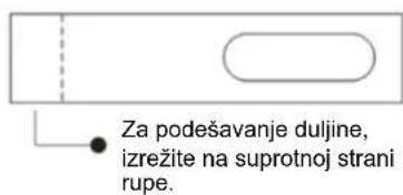
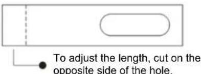
If the window opening is shorter than the minimum length of the window glider set, cut the end without the support short enough to fit into the window opening. Never cut out the hole in the window glider set.
natural_image
Simple line drawing of a cylindrical object with a circular inset, no text or symbols present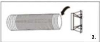
natural_image
Diagram of a cylindrical object with a triangular structure attached, labeled '3.' (no text or symbols on the object itself)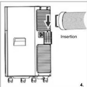
BE COOL
RECOMMENDATION FROM BE COOL
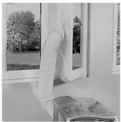
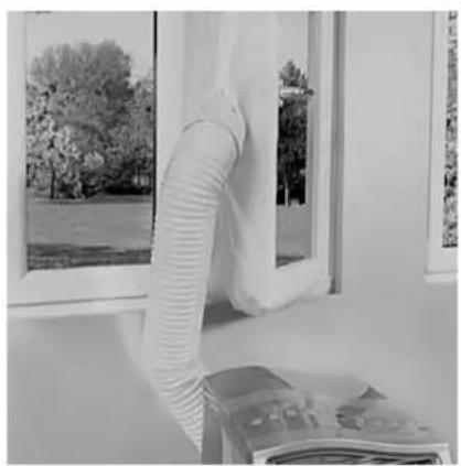
We recommend a SHE Hot-Air Stop when installing on windows, balcony doors or sliding doors.
These offer the following advantages:
- No warm air flows into the living space→ therefore energy saving
- Simple and fast assembly
• Durable, water repellent material - Opening and closing possible
- Washable
Available from your air conditioner supplier.
natural_image
Interior view of a room with a large white hose and window, overlooking trees and a window (no visible text or symbols)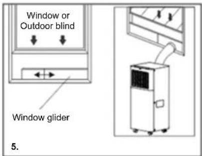
Installation of the window guides
Step 1: Materials
A) Main panel
B) Plate with hole
C) Screw/Pin
Step 2: Assembly
Insert panel B into the main panel A and adjust it to the window width. Note that window sizes may vary. Make sure that you do not have any gaps or air pockets in the window assembly when measuring the window width.

Step 3: Fastening the screw/pin
Fasten the screws/pins in the appropriate holes. Ensure that no gaps or air pockets remain in the window assembly after installation by selecting the correct width for your window.
BE COOL
Location
- The unit should be placed on a stable, solid surface to minimize noise and vibration. Ensure that the surface is level, smooth and sufficiently load-bearing to support the unit.
- Although the device has casters that make it easier to move, it should only be moved on smooth, level surfaces. Be especially careful when moving it on carpeted floors to avoid damaging the floor. Avoid rolling the device over obstacles.
- The device must be placed near a properly grounded outlet.
- Make sure that there are no obstacles near the air inlet or air outlet openings of the device.
- For efficient performance, maintain at least 18 inches (45 cm) from the wall.
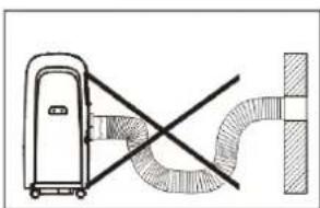
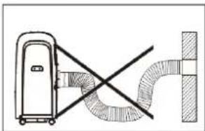
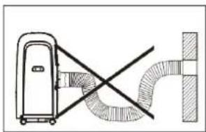
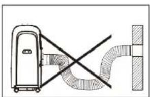
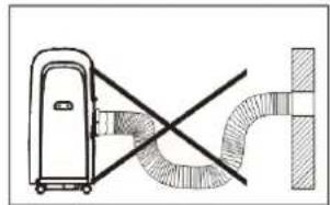
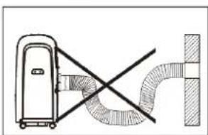
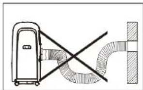
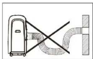
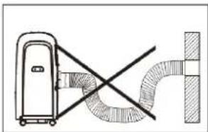
- If you must extend the hose, be sure to keep the length to a minimum. Avoid sharp bends or slack in the hose.
natural_image
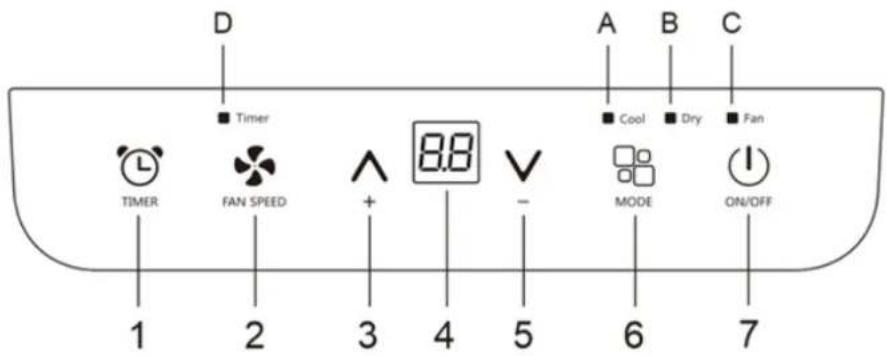
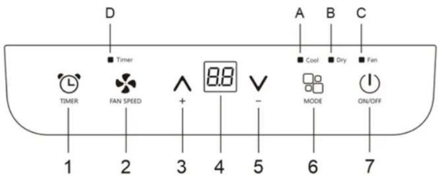
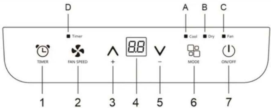
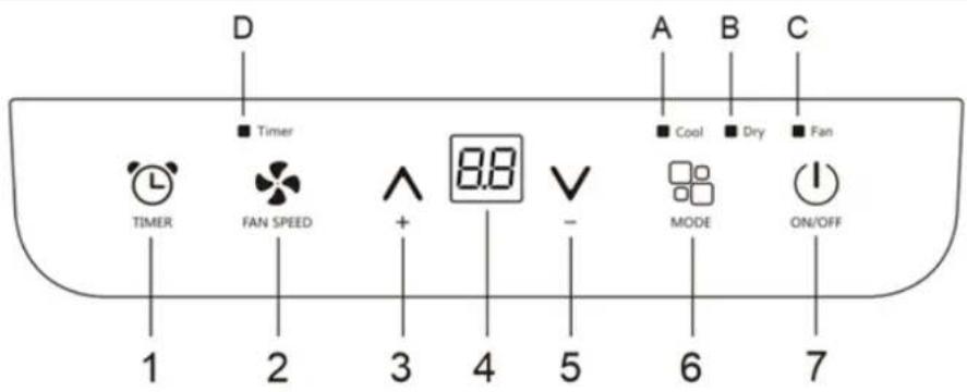
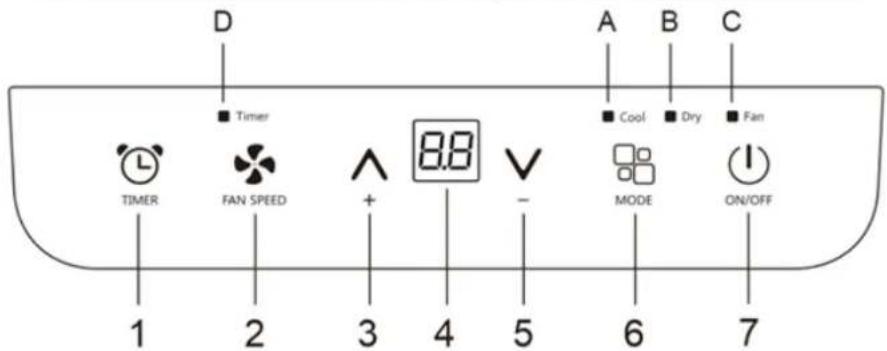
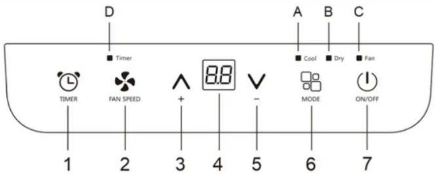
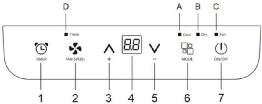
Diagram showing a device connected to a curved pipe with a diagonal line crossing it (no text or symbols present)CONTROL PANEL AND REMOTE CONTROL

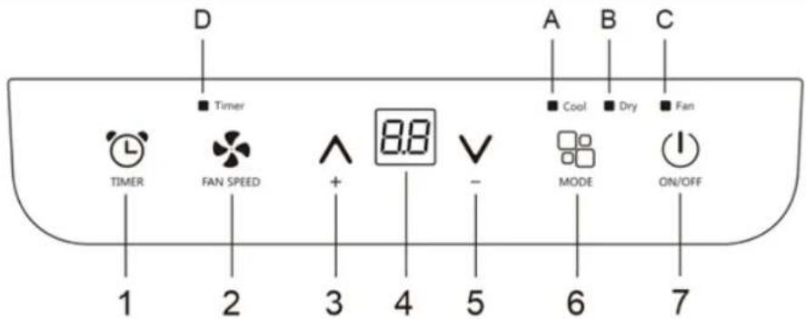
-
timer key
-
fan button
-
increase key
-
display
-
"Decrease" key
-
mode button
-
ON/OFF button
A. Cooling indicator
B. Dehumidify indicator
C. Fan indicator
D. Timer indicator
SWITCHING ON THE DEVICE
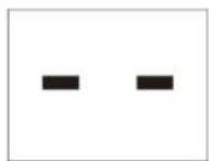
Insert the power plug into the power outlet to put the device into standby mode.
Press the On/Off key to switch on the device. The device displays the last function used that was active when it was switched off.
BE COOL
Note: To turn off the device, never simply unplug the power cord from the wall outlet. Always use the on/off button ^① and then wait a few minutes before unplugging the power cord. This allows the device to perform a control cycle to check the operating status.
COOLING MODE
Cooling mode is ideal for hot, humid weather conditions when you want to cool and dehumidify the room. Follow these steps to set the mode correctly:
Press the "☐key repeatedly until the "Cool" symbol appears on the display.
Use the " + " or " - " keys to select the target temperature between 18°C and 32°C (64°F to 90°F). Press the corresponding keys until the desired temperature is displayed.
Select the desired blower level by pressing the "key:
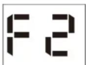
- F2 High: This mode allows the desired temperature to be reached as quickly as possible.
- F1 Low: In low mode, the device runs more quietly.
The recommended room temperature during summer is usually between 24^ C and 27^ C ( 75^ F to 81^ F). However, it is recommended not to lower the temperature much below the outdoor temperature. Note that the difference in fan speed is more noticeable in fan mode than in cooling mode.
FAN MODE
In fan mode, the air hose does not need to be connected. Follow these steps to set this mode correctly:
- Press the " "key repeatedly until the "Fan" symbol is displayed.
- Select the desired fan level by pressing the " " key to choose between High and Low.
As shown in the figure below:
High
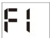
Low
ENTFEUTABLE
Dehumidify mode is ideal for reducing indoor humidity, especially during the spring and fall seasons or in humid environments. Before using the dehumidify mode, prepare the unit as required for the cooling mode and make sure that the exhaust hose is connected so that the humidity can be discharged to the outside.
How to set this mode correctly:
BE COOL
- Press the " ☐" button repeatedly until the "Dehumidify" icon lights up and the screen displays " ☐"
- In this mode, the blower speed is automatically selected by the device.
SETTING THE TIMER
The timer function allows you to program the unit to turn on and off to optimize energy consumption and avoid unnecessary power consumption.
How to program the switch-on time:
Switch on the unit and select the desired operating mode, e.g. cooling, 24^ C, high fan speed. Then switch off the device.
- Press the " ℓ " button, causing the "Timer" icon and the number of hours to flash.
- Use the " " / " " button to set the desired time.
- Wait about 5 seconds until the timer is activated. The "Timer" symbol lights up.
- If you want to cancel the timer, press the timer key again or the key. This deactivates the timer and the "Timer" icon disappears from the screen.
Deactivation of timer programming:
- When the device is in operation, press the " ℓ " button so that the "Timer" symbol and the number of hours flash.
- Use the "^ ^ " keys to set the desired time.
- Wait about 5 seconds to activate the timer, meanwhile the "Timer" icon will be lit.
- If you want to deactivate the timer, press either the timer key " 🔊 " or the on/off key " ⏻ " again. This will cancel the timer and the "Timer" icon will disappear from the screen.
CHANGING THE TEMPERATURE UNIT
While the unit is operating, press and hold the " + and " " buttons simultaneously for 3 seconds to change the temperature unit.
Example:
Before the change, the screen as shown in Figure 1 in is displayed in cooling mode. After the change, the screen as shown in Figure 2 is displayed in cooling mode.
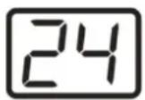
1. °C
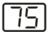
2. °F
BE COOL
REMOTE CONTROL
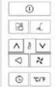 |  | On/Off button |  | Fan speed button |
 | Increase button |  — — | Mode button | |
 — — | Decrease" key |  — — | Sleep mode | |
 — — | Timer button | NOTICE:This series model does not have an automatic swivel function. | ||
 | Unit switch button | |||
NOTICE:
- Point the remote control at the receiver on the device.
- The remote control must not be further than 7 meters from the device (without obstacles between the remote control and the receiver).
- The remote control must be handled with extreme care. Do not drop it or expose it to direct sunlight or heat sources. If the remote control does not work, please remove and reinsert the battery.
Initial start-up of the remote control or replacement of the betterien:
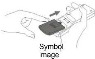
- Remove the cover on the back of the remote control.
- Insert two "AAA" 1.5V batteries in the correct position (see instructions inside the battery compartment)
Safety instructions for battery replacement:
- When the remote control is replaced or disposed of, the batteries must be removed and disposed of in accordance with current legislation, as they are harmful to the environment.
- Do not mix old and new batteries. Do not mix alkaline, standard (carbon zinc) or rechargeable (nickel cadmium) batteries.
- Do not dispose of batteries in fire. Batteries can explode or leak.
- If the remote control will not be used for a long time, remove the batteries.
NOTE
If the remote control needs to be replaced or disposed of, the batteries must be removed and disposed of properly according to valid regulations!
Also remove the batteries if the remote control will not be used for a long time to prevent corrosion damage.
If the batteries need to be replaced, always replace both with ones of the same type and state of charge.
BE COOL
SLEEP MODE
The sleep mode is particularly suitable for nighttime use, as it gradually reduces the operation of the device.
To set this mode properly, follow these steps:
- Select the cooling mode according to the previous instructions.
- Press the "button.
- The device is set to the previously selected operating mode.
- When sleep mode is enabled, the screen brightness is reduced and the fan speed is lower.
The sleep mode ensures that the room maintains an optimal temperature without causing sharp fluctuations in temperature or humidity, while operating quietly. The fan speed always remains low while the room temperature and humidity change gradually to ensure maximum comfort.
In cooling mode, the preset temperature is increased by 1^ C ( 1^ F) per hour within 2 hours. This new temperature is maintained for the next 6 hours before the device switches off.
Sleep mode can be deactivated at any time during operation by pressing the "Sleep", "Mode" or "Fan speed" keys. Note that sleep mode is also available in dehumidification mode.
SELF-DIAGNOSIS:
This device is equipped with a self-diagnosis function that can detect various malfunctions. When malfunctions occur, corresponding warnings are shown on the display of the device.
| ERROR CODE | SOLUTION | |
 | ERROR(Sensor damaged) | If this is displayed, contact your local authorized service center or our customer service department. |
 | FULL TANK(condensation water tank full) | Empty the internal condensation water tank, according to the instructions in the "End of the season" Paragraph. |
BE COOL
TIPS FOR THE CORRECT APPLICATION
Find here some tips to achieve the optimal performance of the air conditioner:
| Close windows and doors in the room to be air-conditioned. | 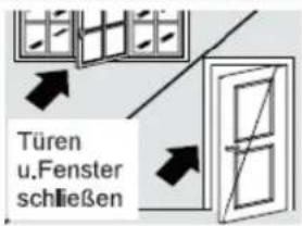 |
| Protect the room from direct sunlight with curtains, blinds or shutters. This will save you energy. | 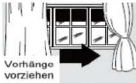 |
| Do not place any objects on the unit and do not cover the air inlet and air outlet. Keep the grids clear. | |
| Make sure that no heat sources are operating in the room. | |
| Never use the device in very humid rooms (e.g. laundry rooms). | |
| Do not use the device outdoors. | |
| Make sure that the air conditioner is placed on a level floor. | |
Method of water removal:
If too much condensed water accumulates inside the device and the device stops operating, the message "FULL TANK" (as described in the self-diagnosis) is displayed. In this case, the condensed water must be drained using the following procedures:
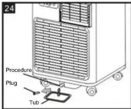
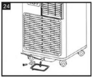
Manual draining (Figure 24):
In regions with high humidity, it may be necessary to drain the water manually.
- Disconnect the device from the power source.
- Place a drip pan under the lower drain plug as shown in the figure.
- Remove the lower drain plug.
- The water will drain into the drip pan (the drip pan may not be included).
• After the water has been drained, re-tighten the lower drain plug. - Switch the device on again.
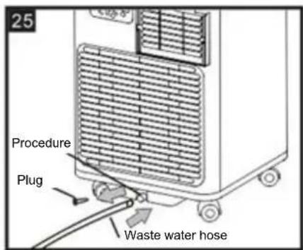
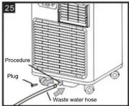
Continuous drainage (Figure 25):
- Disconnect the device from the power source.
- Remove the drain plug. During this process, some residual water may escape, so you should have a drip tray (not included) ready.
- Connect a 1/2 inch (12.7 mm) diameter drain hose (the hose may not be included) as shown in the illustration.
BE COOL
- The water can continuously drain through the hose into a floor drain or bucket.
- Switch the device on again.
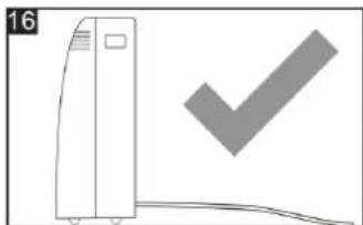
NOTICE:
Make sure that the height and cross-section of the drain hose are not higher than the drain, otherwise the water tank cannot be drained. (Fig.16 and Fig.17)
natural_image
Simple line drawing of a vertical stacker with a checkmark symbol (no text or labels)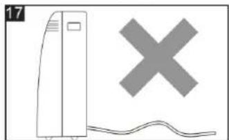
natural_image
Illustration of a server tower with a gray X symbol and a wavy line below (no text or symbols present)CLEANING
Before cleaning or servicing the unit, turn it off by pressing the button on the control panel or remote control, wait a few minutes, and then unplug the power cord from the wall outlet.
Cleaning the housing
Clean the housing of the device with a slightly damp cloth and then dry it thoroughly with a dry cloth.
Never use water to wash the device as this can be dangerous.
Never clean the device with gasoline, alcohol or solvents.
Never spray insecticide liquids or similar substances on the device.
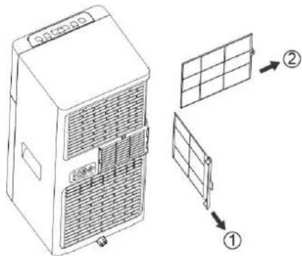
Cleaning the air filter
To ensure that your unit works efficiently, you should clean the filter once a week while it is in operation. Remove the evaporator filter according to the illustration.
Be careful to avoid the metal parts of the unit to prevent injury from possible cuts while removing or reinstalling the filter.
Use a vacuum cleaner to remove dust accumulations from the filter. If the filter is very dirty, you can clean it in warm water and rinse it several times. Make sure the water is never hotter than 40^ (104°F).
After washing, allow the filter to dry completely and then replace the intake grille on the unit.
BE COOL
START AND END OF SEASON
CHECKS AT THE BEGINNING OF THE SEASON
Make sure that the power cord and plug are undamaged and that the grounding system is working properly. Follow the installation instructions carefully.
END OF SEASON MEASURES
To completely drain the internal circuit, remove the lid.
natural_image
Diagram of a portable air conditioner unit with cooling fan and battery (no text or symbols)Drain the remaining water into a bowl.
After all the water has drained, replace the lid.
Clean the filter thoroughly and allow it to dry completely before reinserting it.
ERROR SEARCH
| PROBLEM | CAUSE | SOLUTION |
| The device does not turn on | - There is no power- It is not connected to the mains- The internal safety device has tripped | - Wait- Connection to the mains- Wait 30 minutes, if the problem persists, contact your dealer or our service center. |
| The device works only for a short time | The exhaust air hose is not routed correctlySomething prevents the Air from the outlet | Lay exhaust air hose correctly, keeping it as short and free of curves as possible to avoid bottlenecksCheck and remove any obstacles blocking the air outlet |
| The device works but not cool the room | Windows, doors and/or curtains open | Close doors, windows and Curtains, taking into account the "Tips for the correct application" given via |
| There are heat sources in the room (stove, hair dryer, etc.) | Eliminate the heat sources | |
| The exhaust air hose is removed from the unit | Insert the exhaust hose into the housing at the rear of the unit | |
| The technical specification of the device is not suitable for the room in which it is installed. |
BE COOL
| During operation there is an unpleasant smell in the room | Air filter clogged | Clean the filter as described via |
| The device does not work for about three minutes after reboot | The internal safety of the compressorPrevents the device from restarting before three minutes have elapsed since it was last turned off | Wait. This delay is part of normal operation |
| The following message appears on the display:PF / FE | The device has a self-diagnostic system that can detect a number of malfunctions | See SELF-DIAGNOSIS Chapter |
| Technical information | |
| Item number | BC7KL24FWV2 |
| Cooling capacity | 7,000 BTU/h |
| Power consumption (cooling) | 2,055 watts |
| Max. Power consumption | 790 watts |
| Input voltage | 220 - 240 V |
| Frequency | 50 Hz |
| WIFI transmission frequency | 2,4GHz |
| Transmitting power: | max. 100mW |
| Refrigerant/Filling | R290 |
| Energy efficiency EER | 2,6 |
| Energy efficiency class | A |
| Air circulation | 320m3/h |
| Noise level (sound power) | 65dB |
| Weight | 19,6 kg |
| Dimensions | 290×675×280 mm |
| Contact address for further information | Schuss Home Electronic GmbHScheringgasse 3, A-1140 ViennaTel: +43 (1) 97 0 21 - 0Service line: +43 (1) 97 0 21 - 502www.becool.atFB-No: 236974 t / FB-Court: Vienna |
BE COOL
| Information requirements for single duct and double duct air conditionier | P | ||
| Information to identify the model(s) to which the information relates to [fill in as necessary]: | |||
| Description | Symbol | Value | Unit |
| Rated capacity for cooling | P_rated for cooling | 2.05 | kW |
| Rated capacity for heating | P_rated for heating | - | KW |
| Rated power input for cooling | P_EER | 0.790 | kW |
| Rated power input for heating | P_COP | - | kW |
| Rated Energy efficiency ratio | EER_d | 2.60 | - |
| Rated Coefficient of performance | COP_d | - | - |
| Information to identify the model(s) to which the information relates to [fill in as necessary]: | |||
| Description | Symbol | Value | Unit |
| Power consumption in thermostat-off mode | P_TO | N/A | W |
| Power consumption in standby P mode | P_SB | 0.5 | W |
| Electricity consumption of single/double duct appliances (indicate for cooling and heating separately) | Q_SD | SD: 0.790 (cooling) | kWh/h |
| Sound power level | L_WA | 65 | dB(A) |
| Global warming potential | GWP | 3 | kgCO2 eq. |
| Contact details for obtaining more information | Schuss Home Electronic GmbH Scheringgasse 31140 Vienna, AustriaTel.: +43 (1) 97 0 21 - 0www.becool.at | ||
BE COOL
WARRANTY
With this quality product from BE COOL you have made a decision for innovation, durability and reliability.
For this BE COOL device we grant a warranty period of 2 years from the date of purchase valid in Austria! If, contrary to expectations, service work on your device should nevertheless be necessary during this period, we hereby guarantee to repair (spare parts and labor) or (at the discretion of Schuss) to exchange the product free of charge. Should neither repair nor exchange be possible for economic reasons, we reserve the right to issue a current value credit note.
In the case of air conditioners, please contact the customer hotline as a first step (see sticker on the device or title page of the operating instructions), in the case of fans, please contact your specialist dealer or us directly. We would like to point out that repair work that has not been carried out by the authorized contract workshop in Austria will immediately terminate the validity of this warranty.
Not covered by this warranty:
• Repair or replacement of parts due to normal wear and tear
- Damage due to non-observance of the operating instructions
• Devices that are used - even only partially - for commercial purposes
- equipment mechanically damaged by external influence (fall, impact, breakage, improper use, etc.) as well as wear and tear of an aesthetic nature.
• Devices that have been improperly handled
• Devices that have not been opened by our authorized service workshop.
- Damage caused as a result of improperly closed condensate drain valves of air conditioners or improperly inserted water tank.
- Unmet consumer expectations.
- Damage caused by force majeure, water, lightning, overvoltage.
- Devices where the type designation and/or serial number on the device has been changed, deleted, made illegible or removed.
- services outside our authorized workshops, the transport costs to an authorized workshop or to us and back, and the associated risks.
We emphatically point out that within the warranty period, in case of operating errors or if no error was detected, a lump sum of € 60,- (indexed basis CPI 2015, June 2020) will be charged.
The provision of warranty service (repair or replacement of the device) does not extend the absolute warranty period of 2 years from the date of purchase.
The 2-year warranty is only valid on presentation of the purchase receipt (must contain the name and address of the dealer as well as the complete device designation) and the associated warranty certificate, on which the device type as well as the serial number (visible on the box and on the back or bottom of the device) must be noted! Without presentation of the warranty certificate, only the legal warranty applies!
We expressly point out that the statutory warranty rights are not affected by this warranty and continue undiminished.
Schuss Home Electronic GmbH and its vicarious agents shall only be liable for damages in the event of gross negligence or intent. Excluded is in any case the liability for lost profit, expected but not occurred savings, consequential damages and damages from third party claims. Damages to or for recorded data are always excluded from the liability for damages.
Congratulations on your choice. We wish you much pleasure with your BE COOL device!
ADDRESS
BE COOLDistribution
Schuss Home Electronic GmbH
1140 Vienna, Scheringgasse 3
Tel.: +43 (0)1/ 970 21
Type designation:......
Serial number:......
In the event of a warranty claim, this warranty certificate must be handed over together with the device to the authorized service workshop or the dealer from whom you purchased the device!
BE COOL
WICHTIG!

These instructions are only for the BE COOL-Service center!
A Service or repairing of the device must only be performed by a qualified technician who is allowed to handle the R290 refrigerant.
Do not attempt to repair or open the case of the air conditioner yourself → this leads to the immediate loss oft he warranty.
INSTRUCTIONS FOR REPAIRING APPLIANCES CONTAINING R290
1 GENERAL INSTRUCTIONS
1.1 Checks to the area
Prior to beginning work on systems containing flammable refrigerants, safety checks are necessary to ensure that the risk of ignition is minimized. For repair to the refrigerating system, the following precautions shall be complied with prior to con-ducting work on the system.
1.2 Work procedure
Work shall be undertaken under a controlled procedure so as to minimize the risk of a flammable gas or vapor being present while the work is being performed.
1.3 General work area
All maintenance staff and others working in the local area shall be instructed on the nature of work being carried out. Work in confined spaces shall be avoided. The area around the workspace shall be sectioned off. Ensure that the conditions within the area have been made safe by control of flammable material.
1.4 Checking for presence of refrigerant
The area shall be checked with an appropriate refrigerant detector prior to and during work, to ensure the technician is aware of potentially flammable atmospheres. Ensure that the leak section equipment being used is suitable for use with flammable refrigerants, i.e. non sparking, adequately sealed or intrinsically safe.
1.5 Presence of fire extinguisher
If any hot work is to be conducted on the refrigeration equipment or any associated parts, appropriate fire extinguishing equipment shall be available to hand. Have a dry powder or CO 2 fire extinguisher adjacent to the charging area.
BE COOL
1.6 No ignition sources
No person carrying out work in relation to a refrigeration system which involves exposing any pipe work that contains or has contained flammable refrigerant shall use any sources of ignition in such a manner that it may lead to the risk of fire or explosion. All possible ignition sources, including e-cigarette smoking, should be kept sufficiently far away from the site of installation, repairing, removing and disposal, during which flammable refrigerant can possibly be released to the surrounding space. Prior to work taking place, the area around the equipment is to be surveyed to make sure that there are no flammable hazards or ignition risks. "No Smoking" signs shall be displayed.
1.7 Ventilated area
Ensure that the area is in the open or that it is adequately ventilated before breaking into the system or conducting any hot work. A degree of ventilation shall continue during the period that the work is carried out. The ventilation should safely disperse any released refrigerant and preferably expel it externally into the atmosphere.
1.8 Checks to the refrigeration equipment
Where electrical components are being changed, they shall be fit for the purpose and to the correct specification. At all times the manufacturer's maintenance and service guidelines shall be followed. If in doubt consult the manufacturer's technical department for assistance. The following checks shall be applied to installations using flammable refrigerants: the charge size is in accordance with the room size within which the refrigerant containing parts are installed; the ventilation machinery and outlets are operating adequately and are not obstructed; if an indirect refrigerating circuit is being used, the secondary circuit shall be checked for the presence of refrigerant; marking to the equipment continues to be visible and legible. Markings and signs that are illegible shall be corrected; refrigeration pipe or components are installed in a position where they are unlikely to be exposed to any substance which may corrode refrigerant containing components, unless the components are constructed of materials which are inherently resistant to being corroded or are suitably protected against being so corroded.
1.9 Checks to electrical devices
Repair and maintenance to electrical components shall include initial safety checks and component inspection procedures. If a fault exists that could compromise safety, then no electrical supply shall be connected to the circuit until it is satisfactorily dealt with. If the fault cannot be corrected immediately but it is necessary to continue operation, an adequate temporary solution shall be used. This shall be reported to the owner of the equipment so all parties are advised.
Initial safety checks shall include: Those capacitors are discharged: this shall be done in a safe manner to avoid possibility of sparking; that there no live electrical components and wiring are exposed while charging, recovering or purging the system; that there is continuity of earth bonding.
2 REPAIRS TO SEALED COMPONENTS
2.1 During repairs to sealed components, all electrical supplies shall be disconnected from the equipment being worked upon prior to any removal of sealed covers, etc. If it is absolutely necessary to have an electrical supply to equipment during servicing, then a permanently operating form of leak detection shall be located at the most critical point to warn of a potentially hazardous situation.
2.2 Particular attention shall be paid to the following to ensure that by working on electrical components, the casing is not altered in such a way that the level of protection is affected.
This shall include damage to cables, excessive number of connections, terminals not made to original specification, damage to seals, incorrect fitting of glands, etc. Ensure that apparatus is mounted securely. Ensure that seals or sealing materials have not degraded such that they no longer serve the purpose of preventing the ingress of flammable atmospheres. Replacement parts shall be in accordance with the manufacturer's specifications.
NOTE The use of silicon sealant may inhibit the effectiveness of some types of leak detection equipment. Intrinsically safe components do not have to be isolated prior to working on them.
3 REPAIR TO INTRINSICALLY SAFE COMPONENTS
Do not apply any permanent inductive or capacitance loads to the circuit without ensuring that this will not exceed the permissible voltage and current permitted for the equipment in use.
BE COOL
Intrinsically safe components are the only types that can be worked on while live in the presence of a flammable atmosphere. The test apparatus shall be at the correct rating. Replace components only with parts specified by the manufacturer. Other parts may result in the ignition of refrigerant in the atmosphere from a leak.
4 CABLING
Check that cabling will not be subject to wear, corrosion, excessive pressure, vibration, sharp edges or any other adverse environmental effects. The check shall also take into account the effects of aging or continual vibration from sources such as compressors or fans.
5 DETECTION OF FLAMMABLE REFRIGERANTS
Under no circumstances shall potential sources of ignition be used in the searching for or detection of refrigerant leaks. A halide torch (or any other detector using a naked flame) shall not be used.
6 LEAK DETECTION METHODS
The following leak detection methods are deemed acceptable for systems containing flammable refrigerants. Electronic leak detectors shall be used to detect flammable refrigerants, but the sensitivity may not be adequate, or may need recalibration. (Detection equipment shall be calibrated in a refrigerant-free area.) Ensure that the detector is not a potential source of ignition and is suitable for the refrigerant used. Leak detection equipment shall be set at a percentage of the LFL of the refrigerant and shall be calibrated to the refrigerant employed and the appropriate percentage of gas (25 % maximum) is confirmed. Leak detection fluids are suitable for use with most refrigerants but the use of detergents containing chlorine shall be avoided as the chlorine may react with the refrigerant and corrode the copper pipe-work. If a leak is suspected, all naked flames shall be removed/extinguished. If a leakage of refrigerant is found which requires brazing, all of the refrigerant shall be recovered from the system, or isolated (by means of shut off valves) in a part of the system remote from the leak. Oxygen free nitrogen (OFN) shall then be purged through the system both before and during the brazing process.
7 REMOVAL AND EVACUATION
When breaking into the refrigerant circuit to make repairs – or for any other purpose – conventional procedures shall be used. However, it is important that best practice is followed since flammability is a consideration. The following procedure shall be adhered to: remove refrigerant; purge the circuit with inert gas; evacuate; purge again with inert gas; open the circuit by cutting or brazing. The refrigerant charge shall be recovered into the correct recovery cylinders. The system shall be “flushed” with OFN to render the unit safe. This process may need to be repeated several times. Compressed air or oxygen shall not be used for this task. Flushing shall be achieved by breaking the vacuum in the system with OFN and continuing to fill until the working pressure is achieved, then venting to atmosphere, and finally pulling down to a vacuum. This process shall be repeated until no refrigerant is within the system. When the final OFN charge is used, the system shall be vented down to atmospheric pressure to enable work to take place. This operation is absolutely vital if brazing operations on the pipework are to take place. Ensure that the outlet for the vacuum pump is not close to any ignition sources and there is ventilation available.
8 CHARGING PROCEDURES
In addition to conventional charging procedures, the following requirements shall be followed.
- Ensure that contamination of different refrigerants does not occur when using charging equipment. Hoses or lines shall be as short as possible to minimize the amount of refrigerant contained in them.
- Cylinders shall be kept upright.
- Ensure that the refrigeration system is earthed prior to charging the system with refrigerant.
- Label the system when charging is complete (if not already).
- Extreme care shall be taken not to overfill the refrigeration system.
- Prior to recharging the system it shall be pressure tested with OFN. The system shall be leak Tested on completion of charging but prior to commissioning. A follow up leak test shall be Carried out prior to leaving the site.
9 DECOMMISSIONING
BE COOL
Before carrying out this procedure, it is essential that the technician is completely familiar with the equipment and all its detail. It is recommended good practice that all refrigerants are recovered safely. Prior to the task being carried out, an oil and refrigerant sample shall be taken in case analysis is required prior to re-use of reclaimed refrigerant. It is essential that electrical power is available before the task is commenced.
- Become familiar with the equipment and its operation.
- Isolate system electrically.
- Before attempting the procedure ensure that :mechanical handling equipment is available, if required, for handling refrigerant cylinders; all personal protective equipment is available and being used correctly; the recovery process is supervised at all times by a competent person; recovery equipment and cylinders conform to the appropriate standards.
- Pump down refrigerant system, if possible.
- If a vacuum is not possible, make a manifold so that refrigerant can be removed from various parts of the system.
- Make sure that cylinder is situated on the scales before recovery takes place.
- Start the recovery machine and operate in accordance with manufacturer's instructions.
- Do not overfill cylinders. (No more than 80 % volume liquid charge).
- Do not exceed the maximum working pressure of the cylinder, even temporarily.
- When the cylinders have been filled correctly and the process completed, make sure
- that the cylinders and the equipment are removed from site promptly and all isolation
- valves on the equipment are closed off.
- Recovered refrigerant shall not be charged into another refrigeration system
- unless it has been cleaned and checked.
10 LABELLING
Equipment shall be labelled stating that it has been de-commissioned and emptied of refrigerant. The label shall be dated and signed. Ensure that there are labels on the equipment stating the equipment contains flammable refrigerant.
11 RECOVERY
When removing refrigerant from a system, either for servicing or decommissioning, it is recommended good practice that all refrigerants are removed safely. When transferring refrigerant into cylinders, ensure that only appropriate refrigerant recovery cylinders are employed. Ensure that the correct number of cylinders for holding the total system charge is available. All cylinders to be used are designated for the recovered refrigerant and labelled for that refrigerant (i.e. special cylinders for the recovery of refrigerant). Cylinders shall be complete with pressure relief valve and associated shut-off valves in good working order. Empty recovery cylinders are evacuated and, if possible, cooled before recovery occurs.
The recovery equipment shall be in good working order with a set of instructions concerning the equipment that is at hand and shall be suitable for the recovery of flammable refrigerants. In addition, a set of calibrated weighing scales shall be available and in good working order. Hoses shall be complete with leak-free disconnect couplings and in good condition. Before using the recovery machine, check that it is in satisfactory working order, has been properly maintained and that any associated electrical components are sealed to prevent ignition in the event of a refrigerant release. Consult manufacturer if in doubt.
The recovered refrigerant shall be returned to the refrigerant supplier in the correct recovery cylinder, and the relevant Waste Transfer Note arranged. Do not mix refrigerants in recovery units and especially not in cylinders.
If compressors or compressor oils are to be removed, ensure that they have been evacuated to an acceptable level to make certain that flammable refrigerant does not remain within the lubricant. The evacuation process shall be carried out prior to returning the compressor to the suppliers. Only electric heating to the compressor body shall be employed to accelerate this process. When oil is drained from a system, it shall be carried out safely.
BE COOL
Competence of service personnel
General
Special training additional to usual refrigerating equipment repair procedures is required when equipment with flammable refrigerants is affected.
In many countries, this training is carried out by national training organizations that are accredited to teach the relevant national competency standards that may be set in legislation.
The achieved competence should be documented by a certificate.
Training
The training should include the substance of the following:
Information about the explosion potential of flammable refrigerants to show that flammables may be dangerous when handled without care.
Information about potential ignition sources, especially those that are not obvious, such as lighters, light switches, vacuum cleaners, electric heaters.
Information about the different safety concepts:
Unventilated – (see Clause GG.2) Safety of the appliance does not depend on ventilation of the housing.
Switching off the appliance or opening of the housing has no significant effect on the safety.
Nevertheless, it is possible that leaking refrigerant may accumulate inside the enclosure and flammable atmosphere will be released when the enclosure is opened.
Ventilated enclosure – (see Clause GG.4) Safety of the appliance depends on ventilation of the housing.
Switching off the appliance or opening of the enclosure has a significant effect on the safety. Care should be taken to ensure a sufficient ventilation before.
Ventilated room – (see Clause GG.5) Safety of the appliance depends on the ventilation of the room.
Switching off the appliance or opening of the housing has no significant effect on the safety. The ventilation of the room shall not be switched off during repair procedures.
Information about the concept of sealed components and sealed enclosures according to IEC 60079-15:2010.
Information about the correct working procedures:
1. Commissioning
- Ensure that the floor area is sufficient for the refrigerant charge or that the ventilation duct is assembled in a correct manner.
- Connect the pipes and carry out a leak test before charging with refrigerant.
- Check safety equipment before putting into service.
2. Maintenance
- Portable equipment shall be repaired outside or in a workshop specially equipped for servicing units with flammable refrigerants.
- Ensure sufficient ventilation at the repair place.
- Be aware that malfunction of the equipment may be caused by refrigerant loss and a refrigerant leak is possible.
- Discharge capacitors in a way that won't cause any spark. The standard procedure to short circuit the capacitor terminals usually creates sparks.
- Reassemble sealed enclosures accurately. If seals are worn, replace them.
- Check safety equipment before putting into service.
3. Repair
- Portable equipment shall be repaired outside or in a workshop specially equipped for servicing units with flammable refrigerants.
- Ensure sufficient ventilation at the repair place.
- Be aware that malfunction of the equipment may be caused by refrigerant loss and a refrigerant leak is possible.
- Discharge capacitors in a way that won't cause any spark.
-
When brazing is required, the following procedures shall be carried out in the right order:
-
Remove the refrigerant. If the recovery is not required by national regulations, drain the refrigerant to the outside. Take care that the drained refrigerant will not cause any danger. In doubt, one person should guard the outlet. Take special care that drained refrigerant will not float back into the building.
• Evacuate the refrigerant circuit. - Purge the refrigerant circuit with nitrogen for 5 min.
BE COOL
- Evacuate again.
- Remove parts to be replaced by cutting, not by flame.
- Purge the braze point with nitrogen during the brazing procedure.
- Carry out a leak test before charging with refrigerant.
- Reassemble sealed enclosures accurately. If seals are worn, replace them.
- Check safety equipment before putting into service.
4. Decommissioning
If the safety is affected when the equipment is put out of service, the refrigerant charge shall be removed before decommissioning.
o Ensure sufficient ventilation at the equipment location.
- Be aware that malfunction of the equipment may be caused by refrigerant loss and a refrigerant leak is possible.
- Discharge capacitors in a way that won't cause any spark.
- Remove the refrigerant. If the recovery is not required by national regulations, drain the refrigerant to the outside. Take care that the drained refrigerant will not cause any danger. In doubt, one person should guard the outlet. Take special care that drained refrigerant will not float back into the building.
- Evacuate the refrigerant circuit.
o Purge the refrigerant circuit with nitrogen for 5 min.
- Evacuate again.
- Fill with nitrogen up to atmospheric pressure.
- Put a label on the equipment that the refrigerant is removed.
5. Disposal
-
Ensure sufficient ventilation at the working place.
○ Remove the refrigerant. If the recovery is not required by national regulations, drain the refrigerant to the outside. Take care that the drained refrigerant will not cause any danger. In doubt, one person should guard the outlet. Take special care that drained refrigerant will not float back into the building. -
Evacuate the refrigerant circuit.
o Purge the refrigerant circuit with nitrogen for 5 min. - Evacuate again.
- Cut out the compressor and drain the oil.
Transportation, marking and storage for units that employ flammable refrigerants Transport of equipment containing flammable refrigerants
Attention is drawn to the fact that additional transportation regulations may exist with respect to equipment containing flammable gas. The maximum number of pieces of equipment or the configuration of the equipment, permitted to be transported together will be determined by the applicable transport regulations.
Marking of equipment using signs
Signs for similar appliances used in a work area generally are addressed by local regulations and give the minimum requirements for the provision of safety and/or health signs for a work location.
All required signs are to be maintained and employers should ensure that employees receive suitable and sufficient instruction and training on the meaning of appropriate safety signs and the actions that need to be taken in connection with these signs.
The effectiveness of signs should not be diminished by too many signs being placed together. Any pictograms used should be as simple as possible and contain only essential details.
Disposal of equipment using flammable refrigerants
See national regulations.
Storage of equipment/appliances
The storage of equipment should be in accordance with the manufacturer's instructions. Storage of packed (unsold) equipment Storage package protection should be constructed such that mechanical damage to the equipment inside the package will not cause a leak of the refrigerant charge. The maximum number of pieces of equipment permitted to be stored together will be determined by local regulations.
DECLARATION OF CONFORMITY
(I) Schuss Home Electronic GmbH
Scheringgasse 3, 1140 Wien, AUSTRIA
(II)
Declares, that the product
Manufacturer
Hersteller
is conformity with following directives, norms and/or regulations:
(III)
of 16 April 2014 amending Directives 2003/71/EC and 2009/138/EC and Regulations (EC) No 1060/2009, (EU) No 1094/2010 and (EU) No 1095/2010 in respect of the powers of the European Supervisory Authority (European Insurance and Occupational Pensions Authority) and the European Supervisory Authority (European Securities and Markets Authority)
EN IEC 55014-1:2021
EN IEC 55014-2: 2021
EN 61000-3-3: 2013+ A1:2019+A2:2021
EN 301489-1V2.2.3
EN 301489-17 V3.2.4
EN 300328 V2.2.2
EN IEC 62311:2020
EMC Directive (EMC): 2014/30/EU Directive of the European Parliament and of the Council of 26 February 2014 on the harmonisation of the laws of the Member States relating to electromagnetic compatibility; Official Journal of the EU L96, 29/03/2014, p. 79–106
Low Voltage Directive (LVD):2014/35/EU Directive of the European Parliament and of the Council of 26
February 2014 on the harmonisation of the laws of the Member States relating to the making available on the market of electrical equipment designed for use within certain voltage limits; Official Journal of the EU L96, 29/03/2014, p. 357–374
EN 60335-2-40: 2003 + A11: 2004 + A12: 2005 + A1: 2006 + A2: 2009 + A13: 2012
BE COOL
EN 60335-1: 2012 + A11: 2014 + A13: 2017 + A1: 2019 + A14: 2019 + A2: 2019 + A15: 2021 EN 62233: 2008
Ökodesign-Richtlinie Energy-Related-Products-Directive (ErP)2009/125/EC;
Official Journal EU L285/10-35 (31.10.2009) and associated regulation 2015/1188
RoHS Directive: 2011/65/EU Directive of the European Parliament and of the Council of 8 June 2011 on the restriction of the use of certain hazardous substances in electrical and electronic equipment; Official Journal of the EU L174, 1/07/2011, p. 88–110
Reach SVHC(EC)NO. 1907/2006 Schuss Home Electronic GmbH hereby confirms that in the products we supply, there are no substances of very high concern (SVHC) in the candidate list (last ECHA update from June 14, 2023, 235 substances) above 0.1% in accordance with Article 33 of the REACH Regulation (EC) No .1907/2006 are included.
Place and date of issue:
Vienna, 2025-09-04
Bevollmächtigter Vertreter des Herstellers Authorized representative of manufacture
Scharl, Alexander
Senior product and purchasing manager i.V.
Declaration reference:
SCHUSS HOME ELECTRONIC GMBH
Scheringgasse 3, 1140 Wien, AUSTRIA


- REINIGUNG
- BE COOL
- MANUEL D'INSTRUCTION
- Climatiseur mobile BC7KL24FWV2
- NETTOYAGE
- IMPORTANTI INFORMAZIONI SULLA SICUREZZA, L'UBICAZIONE E IL COLLEGAMENTO ELETTRICO.
- ACCENSIONE DEL DISPOSITIVO
- PULIZIA
- Mobiele airconditioner BC7KL24FWV2
- BELANGRIJKE INFORMATIE OVER VEILIGHEID, LOCATIE EN ELEKTRISCHE AANSLUITING.
- HET APPARAAT INSCHAKELEN
- SCHOONMAKEN
- MISSING ZOEKEN
- LIMPIEZA
- GRATULUJEME!
- ZMĚNA JEDNOTKY TEPLOTY
- ČIŠTĚNÍ
- Montáž vodiacich líšt okien
- ZMENA JEDNOTKY TEPLOTY
- ČISTENIE
- Čistenie puzdra
- MANUAL DE INSTRUCTIUNI
- INFORMATII IMPORTANTE PRIVIND SIGURANTA, AMPLASAREA ŞI CONECTAREA ELECTRICĂ.
- CURĂȚARE
- WAŻNE INFORMACJE DOTYCZĄCE BEZPIECZEŃSTWA, LOKALIZACJI I PODŁĄCZENIA ELEKTRYCZNEGO.
- CZYSZCZENIE
- POMEMBNE INFORMACIJE O VARNOSTI, LOKACIJI IN ELEKTRIČNEM PRIKLJUČKU.
- Vgradnja okenskih vodil
- NADZORNA PLOŠČA IN DALJINSKI UPRAVLJALNIK
- ČIŠČENJE
- OBAVIJEST:
- MONTAŽA I MONTAŽA
- Ispušni zrak
- PREPORUKA OD BE COOL
- One nude sljedeće prednosti:
- Ugradnja prozorskih vodilica
- ČIŠĆENJE
- Čišćenje kućišta
- Current operating instructions and other languages
- WARNING
- SPECIFIC INFORMATION ON REFRIGERANT R290
- DESCRIPTION OF THE DEVICE AND SCOPE OF DELIVERY
- Scope of delivery
- NOTICE:
- ASSEMBLY AND INSTALLATION
- Exhaust air
- RECOMMENDATION FROM BE COOL
- These offer the following advantages:
- Installation of the window guides
- Location
- SWITCHING ON THE DEVICE
- COOLING MODE
- FAN MODE
- ENTFEUTABLE
- SETTING THE TIMER
- Deactivation of timer programming:
- CHANGING THE TEMPERATURE UNIT
- Example:
- REMOTE CONTROL
- NOTE
- SLEEP MODE
- SELF-DIAGNOSIS:
- TIPS FOR THE CORRECT APPLICATION
- Method of water removal:
- Manual draining (Figure 24):
- Continuous drainage (Figure 25):
- CLEANING
- Cleaning the housing
- Cleaning the air filter
- START AND END OF SEASON
- CHECKS AT THE BEGINNING OF THE SEASON
- END OF SEASON MEASURES
- WARRANTY
- Not covered by this warranty:
- ADDRESS
- WICHTIG!
- INSTRUCTIONS FOR REPAIRING APPLIANCES CONTAINING R290
- GENERAL INSTRUCTIONS
- Checks to the area
- Work procedure
- General work area
- Checking for presence of refrigerant
- Presence of fire extinguisher
- No ignition sources
- Ventilated area
- Checks to the refrigeration equipment
- Checks to electrical devices
- REPAIRS TO SEALED COMPONENTS
- REPAIR TO INTRINSICALLY SAFE COMPONENTS
- CABLING
- DETECTION OF FLAMMABLE REFRIGERANTS
- LEAK DETECTION METHODS
- REMOVAL AND EVACUATION
- CHARGING PROCEDURES
- DECOMMISSIONING
- LABELLING
- RECOVERY
- Competence of service personnel
- General
- Training
- Commissioning
- Maintenance
- Repair
- Decommissioning
- Disposal
- Transportation, marking and storage for units that employ flammable refrigerants Transport of equipment containing flammable refrigerants
- Marking of equipment using signs
- Disposal of equipment using flammable refrigerants
- Storage of equipment/appliances
- DECLARATION OF CONFORMITY
- Schuss Home Electronic GmbH
Brand : Be Cool
Model : BC7KL24FWV2
Category : Air Conditioning