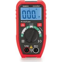
VTTEST22 - Multimeter VELLEMAN - Free user manual and instructions
Find the device manual for free VTTEST22 VELLEMAN in PDF.

User questions about VTTEST22 VELLEMAN
0 question about this device. Answer the ones you know or ask your own.
Ask a new question about this device
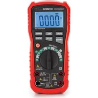
Download the instructions for your Multimeter in PDF format for free! Find your manual VTTEST22 - VELLEMAN and take your electronic device back in hand. On this page are published all the documents necessary for the use of your device. VTTEST22 by VELLEMAN.
USER MANUAL VTTEST22 VELLEMAN
natural_image
Red and black electrical soldering iron with coiled cable (no visible text or symbols)CATIII 400V
USER MANUAL 4
HANDLEIDING 13
MODE D'EMPLOI 22
MANUAL DEL USUARIO 32
To all residents of the European Union
Important environmental information about this product
This symbol on the device or the package indicates that disposal of the device after its lifecycle could harm the environment. Do not dispose of the unit (or batteries) as unsorted municipal waste; it should be taken to a specialized company for recycling. This device should be returned to your distributor or to a local recycling service. Respect the local environmental rules.
If in doubt, contact your local waste disposal authorities.
Thank you for choosing Velleman! Please read the manual thoroughly before bringing this device into service. If the device was damaged in transit, do not install or use it and contact your dealer.
2. Symbols
| AC (Alternating Current) | |
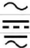 | DC (Direct Current) |
| Both AC and DC | |
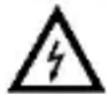 | Risk of Electric shock. A potentially hazardous voltage is possible. |
 | Caution: risk of danger, the manual must be consulted in all cases where this symbol is marked.Warning: a hazardous condition or action that may result in injury or deathCaution: condition or action that may result in damage to the meter or equipment under test |
 | Double insulation (class 2-protection) |
 | Earth |
3. General Guidelines
Refer to the Velleman® Service and Quality Warranty on the last pages of this manual.
VTTEST22
 | This symbol indicates: Read instructionsNot reading the instructions and manual can lead to damage, injury or death. |
 | This symbol indicates: DangerA hazardous condition or action that may result in injury or death. |
 | This symbol indicates: Risk of danger/damageRisk of a hazardous condition or action that may result in damage, injury or death. |
 | This symbol indicates: Attention; important informationIgnoring this information can lead to hazardous situations. |
 | WARNING: To avoid electrical shock always disconnect the test leads prior to opening the housing. To prevent fire hazards, only use fuses with the same ratings as specified in this manual.Remark: refer to the warning on the battery compartment. |
 | Avoid cold, heat and large temperature fluctuations. When the unit is moved from a cold to a warm location, leave it switched off until it has reached room temperature. This to avoid condensation and measuring errors. |
 | Protect this device from shocks and abuse. Avoid brute force when operating. |
 | Pollution degree 2-device. For indoor use only. Keep this device away from rain, moisture, splashing and dripping liquids. Not for industrial use.Refer to §8 Pollution degree. |
 | Keep the device away from children and unauthorised users. |
 | Risk of electric shock during operation. Be very careful when measuring live circuits. |
 | Suitable for live working |
 | There are no user-serviceable parts inside the device.Refer to an authorized dealer for service and/or spare parts. |
VTTEST22

OVC III
This is an installation category CAT III measuring instrument. Refer to §7 Overvoltage/installation category.
Read this addendum and the manual thoroughly. Familiarise yourself with the functions of the device before actually using it.
OVERVOLTAGE CATEGORY III is for equipment intended to form part of a building wiring installation.
IP54
Representing the level of protection from specified external conditions.
5: Dust-protected; 4: Protected against splashing water
All modifications of the device are forbidden for safety reasons. Damage caused by user modifications to the device is not covered by the warranty.
Only use the device for its intended purpose. Using the device in an unauthorized way will void the warranty. Damage caused by disregard of certain guidelines in this manual is not covered by the warranty and the dealer will not accept responsibility for any ensuing defects or problems.
4. Maintenance
There are no user-serviceable parts inside the device. Refer to an authorized dealer for service and/or spare parts.
Before performing any maintenance activities, disconnect the test leads from the jacks.
Do not apply abrasives or solvents to the meter. Use a damp cloth and mild detergent for cleaning purposes.
5. During Use
Risk of electric shock during operation. Be very careful when measuring live circuits.
- Read, understand and follow the Safety Rules and operating instructions in this manual before using this instrument.
- The Voltage Tester is designed to be used by the skilled persons and in accordance with safe methods of work.
- If the equipment is used in a manner not specified by the manufacturer, the protection provided by the equipment may be impaired.
VTTEST22
- Unauthorized persons are not to be allowed to disassemble the tester.
- Keep fingers away from the metal probe tips when taking measurements.
- Comply with all safety codes. Use approved personal protective equipment when working near live electrical circuits.
- Use caution on live circuits. Voltages above 30V AC RMS, 42V AC peak, or 60V DC pose a shock hazard.
- Do not use if the instrument or test leads appear damaged.
- Measure known voltage with the tester to verify that the tester is working properly. If the tester is working abnormally, stop using it immediately. A protective device may be damaged. If there is any doubt, please have the tester inspected by a qualified technician.
- Do not use the tester in wet or damp environments or during electrical storms.
- Do not use the tester near explosive vapors, dust or gasses.
- Do not use the tester if it operates incorrectly. Protection may be compromised.
- Do not apply voltage that exceeds the tester's maximum rated input limits.
- Never use the meter with CAT III installations when measuring voltages that might exceed the safety margin of 400 V above earth ground.
6. General Description
Refer to the illustration on page 2 of this manual:
- L2- test probe with removable covers
- L1 + test probe with removable covers
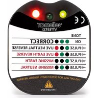
- LED voltage indication display
- Protection ring
7. Overvoltage/Installation Category
Voltage testers are categorized depending on the risk and severity of transient overvoltage that might occur at the point of test. Transients are short-lived bursts of energy induced in a system, e.g. caused by lightning strike on a power line.
VTTEST22
The existing categories according EN 61010-1 are:
| CAT I | A CAT I-rated meter is suitable for measurements on protected electronic circuits that are not directly connected to mains power, e.g. electronics circuits, control signals... |
| CAT II | A CAT II-rated meter is suitable for measurements in CAT I-environments and mono-phase appliances that are connected to the mains by means of a plug and circuits in a normal domestic environment, provided that the circuit is at least 10 m apart from a CAT III- or 20 m apart from a CAT IV-environment. E.g. household appliances, portable tools... |
| CAT III | A CAT III-rated meter is suitable for measurements in CAT I- and CAT II-environments, as well as for measurements on (fixed) mono-or poly-phased appliances which are at least 10 m apart from of a CAT IV-environment, and for measurements in or on distribution level equipment (fuse boxes, lighting circuits, electric ovens). |
| CAT IV | A CAT IV-rated meter is suitable for measuring in CAT I-, CAT II-and CAT III-environments as well as on the primary supply level. Note that for all measurements on equipment for which the supply cables run outdoors (either overhead or underground) a CAT IV meter must be used. |
Warning:
This device was designed in accordance with EN 61010-1 installation category CAT III 400 V. This implies that certain restrictions in use apply that are related to voltages and voltage peaks which can occur within the environment of use. Refer to the table above.
This device is only suitable for measurements up to 400 V in CAT III
8. Pollution Degree
IEC 61010-1 specifies different types of pollution environments, for which different protective measures are necessary to ensure safety. Harsher environments require more protection, and the protection against the pollution which is to be found in a certain environment depends mainly on the insulation and the enclosure properties. The pollution degree rating of the DVM indicates in which environment the device may be used.
| Pollution degree 1 | No pollution or only dry, nonconductive pollution occurs. The pollution has no influence. (only to be found in hermetically sealed enclosures) |
VTTEST22
| Pollution degree 2 | Only nonconductive pollution occurs. Occasionally, temporary conductivity caused by condensation is to be expected. (home and office environments fall under this category) |
| Pollution degree 3 | Conductive pollution occurs, or dry nonconductive pollution occurs that becomes conductive due to condensation that is to be expected.(industrial environments and environments exposed to outside air - but not in contact with precipitation) |
| Pollution degree 4 | The pollution generates persistent conductivity caused by conductive dust or by rain or snow. (exposed outdoor environments and environments where high humidity levels or high concentrations of fine particles occur) |
Warning: This device was designed in accordance with EN 61010-1 pollution degree 2. This implies that certain restrictions in use apply that are related to pollution which can occur within the environment of use. Refer to the table above.
This device is only suitable for measurements in Pollution degree class 2 environments.
9. Specifications
This device is not calibrated when purchased!
Regulations concerning environment of use:
Use this meter only for measurements in CAT I, CAT II and CAT III environments (see §7).
Use this meter only in a pollution degree 2 environment (see §8).
VTTEST22
| Voltage LED steps | ±12,24,50,120,230,400V |
| Accuracy | -30% to 10% of indication |
| Response time | <0.1s |
| AC frequency range | 50/60Hz |
| Operation time | 30s maximum |
| Recovery time | 10 minutes after maximum operation time has been reached |
| Operating Temperature | -15°C to 45°C (5°F to 113°F) |
| Storage temperature | -15°C to 50°C (5°F to 122°F) |
| Relative Humidity | 80% maximum |
| Altitude | 7000ft(2000m) |
| Safety | CAT III 400V ~ |
| Weight | 98.5g |
| Dimension | 223x40x32 mm |
| IP rating | IP54 |
| Resistance | 68kOhm @ 50V a.c. |
| On/off time | 30s ON, 600s OFF |
10. Operation
Performing Tests and Measurements
The bipolar voltage meter consists of two test probes, a connecting cable and the LED indicator panel. Always hold the voltage meter so that you can look straight at the indicator panel. Illuminated indicators can be affected by strong light. For DC measurements, the probe tip L1+ (2) "see image on page 2) is the positive terminal, and the probe tip L2- (1) is the negative terminal. The voltage meter automatically turns on when the test begins (input level >12 V AC/DC) and turns off when the test is complete.
Warnings
Always check that the voltage meter is functioning properly before and after use. First measure a known voltage source (for example, mains voltage 230 V/AC) and check the accuracy of the measurements. Stop use if one or more indication ranges do not function. Do not use a defective voltage meter. Observe the regulations for working with electrical systems. Personal protective equipment must be used when working on systems with hazardous electrical voltage. Follow the technical data in this regard. If the
VTTEST22
'voltage present' indicator appears at a measurement point that is considered disconnected from the system, it is strongly recommended that additional measures be taken (e.g., reduced impedance voltage test, visual inspection of the disconnection point in the power grid, etc.) to detect and establish the 'no operating voltage present' status of the system component under test, such that the voltage indicated by the voltage meter is a fault voltage. If the 'voltage present' indicator does not appear, it is strongly recommended to insert the grounding device before starting work.
The following measurement functions can be performed:
10.1 Two-pole voltage test
Always hold the voltage meter by the handles designed for it. Never protrude beyond the tangible barrier of the handle (4). For voltage tests in the CAT III measurement category, the two insulation caps must be placed over the test probes. This limits the free contact area of the test tip to a maximum of 4 mm. This prevents unintentional short circuits in restricted test conditions (e.g. in junction boxes). Route the two test probes to the test points to be tested. The voltage range is shown in the incremental LED display. The light indicators (+) and (-) show the type of voltage and the corresponding polarity. If both indicators (+) and (-) are lit simultaneously, alternating current ( ) is present. Polarity is indicated only by the two LEDs. When testing built-in sockets, the two insulating covers of the test probes. The longer test probes now allow measurement on a wall outlet.
Warning:
Be sure to keep your hand within reach of the test probe and do not cover the display.
10.2 Phase test
The voltage meter allows the determination of the outer conductor "L1". This can be useful, for example, for tests on sockets. Here the outer conductor can be determined both quickly and easily. Hold the voltage meter by the handles designed for this purpose. Never touch the device outside the handles. To perform the phase test, make sure the installation is correctly connected.
Make contact with the test probe L2- (1) contact with the ground pin (PE) of the socket and test probe L1+ (2) contact with the outer conductor. If the voltage indicator lights up, you have made contact with the outer conductor.
VTTEST22
If there is no indicator, leave test probe L2- (1) on the protective ground and insert test probe L1+ (2) into the second conductor contact of the outlet. There should now be a voltage indication. If there is no voltage indication, check the installation to ensure its proper operation.
Use this device with original accessories only. Velleman group nv cannot be held responsible in the event of damage or injury resulting from (incorrect) use of this device. For more info concerning this product and the latest version of this manual, please visit our website www.velleman.eu. The information in this manual is subject to change without prior notice.
© COPYRIGHT NOTICE
The copyright to this manual is owned by Velleman Group nv. All worldwide rights reserved. No part of this manual may be copied, reproduced, translated or reduced to any electronic medium or otherwise without the prior written consent of the copyright holder.
HANDLEIDING
1. Inleiding
Velleman® Service and Quality Warranty
Since its foundation in 1972, Velleman® acquired extensive experience in the electronics world and currently distributes its products in over 85 countries.
All our products fulfil strict quality requirements and legal stipulations in the EU. In order to ensure the quality, our products regularly go through an extra quality check, both by an internal quality department and by specialized external organisations. If, all precautionary measures notwithstanding, problems should occur, please make appeal to our warranty (see guarantee conditions).
General Warranty Conditions Concerning Consumer Products (for EU):
- All consumer products are subject to a 24-month warranty on production flaws and defective material as from the original date of purchase.
- Velleman® can decide to replace an article with an equivalent article, or to refund the retail value totally or partially when the complaint is valid and a free repair or replacement of the article is impossible, or if the expenses are out of proportion.
You will be delivered a replacing article or a refund at the value of 100% of the purchase price in case of a flaw occurred in the first year after the date of purchase and delivery, or a replacing article at 50% of the purchase price or a refund at the value of 50% of the retail value in case of a flaw occurred in the second year after the date of purchase and delivery.
• Not covered by warranty:
- all direct or indirect damage caused after delivery to the article (e.g. by oxidation, shocks, falls, dust, dirt, humidity...), and by the article, as well as its contents (e.g. data loss), compensation for loss of profits;
- consumable goods, parts or accessories that are subject to an aging process during normal use, such as batteries (rechargeable, non-rechargeable, built-in or replaceable), lamps, rubber parts, drive belts... (unlimited list);
- flaws resulting from fire, water damage, lightning, accident, natural disaster, etc....;
- flaws caused deliberately, negligently or resulting from improper handling, negligent maintenance, abusive use or use contrary to the manufacturer's instructions;
- damage caused by a commercial, professional or collective use of the article (the warranty validity will be reduced to six (6) months when the article is used professionally);
- damage resulting from an inappropriate packing and shipping of the article;
- all damage caused by modification, repair or alteration performed by a third party without written permission by Velleman®.
- Articles to be repaired must be delivered to your Velleman® dealer, solidly packed (preferably in the original packaging), and be completed with the original receipt of purchase and a clear flaw description.
- Hint: In order to save on cost and time, please reread the manual and check if the flaw is caused by obvious causes prior to presenting the article for repair. Note that returning a non-defective article can also involve handling costs.
- Repairs occurring after warranty expiration are subject to shipping costs.
- The above conditions are without prejudice to all commercial warranties.