Black Steel 86715 - Fan UNOLD - Free user manual and instructions
Find the device manual for free Black Steel 86715 UNOLD in PDF.

User questions about Black Steel 86715 UNOLD
0 question about this device. Answer the ones you know or ask your own.
Ask a new question about this device
Download the instructions for your Fan in PDF format for free! Find your manual Black Steel 86715 - UNOLD and take your electronic device back in hand. On this page are published all the documents necessary for the use of your device. Black Steel 86715 by UNOLD.
USER MANUAL Black Steel 86715 UNOLD
natural_image
Black office fan with five blades mounted on a stand, no visible text or symbolsBedienungsanleitung
Instructions for use | Notice d'utilisation Gebruiksaanwijzing | Istruzioni per l'uso Instrucciones de uso | Instrukcja obsługi
Modell 86715
Impressum:
Instructions for use Model 86715
Technical Specifications.... 16
Explanation of the symbols 16
For your safety.... 16
Assembly 19
Operation....22
Cleaning and care....23
Guarantee Conditions 24
Waste Disposal/Environmental Protection ... 24
Service 15
text_image
Technical diagram of a fan assembly with numbered components for identificationnatural_image
Line drawing of a mechanical device with handle and base (no text or symbols)
natural_image
Simple line drawing of a cylindrical object with a side knob (no text or symbols)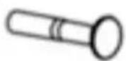
natural_image
Three technical line drawings of mechanical components with no visible text or symbolsCopyright UNOLD AG | www.unold.de
natural_image
Technical line drawings of various fan components and parts, including a speaker, fan base, and mechanical parts (no text or labels)text_image
Diagram illustrating the process of a device's internal components before and after assembly, with Chinese labels.Copyright UNOLD AG | www.unold.de
natural_image
Four technical line drawings of a mechanical device with no visible text or symbolsBEDIENEN
natural_image
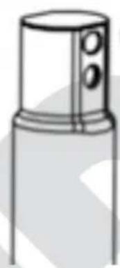
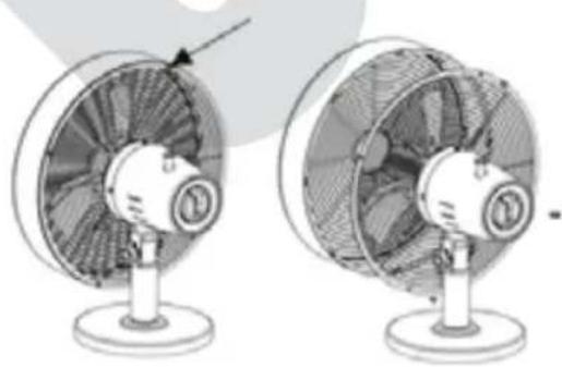
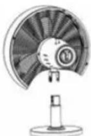
Two views of a desktop fan with visible blades and mounting base (no text or symbols)Weight: Approx. 3.1 kg
Diameter: 33 cm
Power cord length: Approx. 160 cm
Housing: Metal
Features: 3 speed levels, oscillation can be s witched carrying handle on the housing
Accessories: Operating instructions

Equipment features, technology, colours and design are subject to change without notice.
EXPLANATION OF THE SYMBOLS
This symbol indicates potential hazards that may result in injury or damage to the appliance.
FOR YOUR SAFETY
Please read the following instructions and keep them on hand for later reference.
Instructions for persons in the household
- This appliance can be used by children 8 years and older, as well as by persons with reduced physical, sensory or mental abilities or with lack of experience and/or knowledge, if they are supervised or if they have been instructed with regard to safe use of the appliance and have understood the dangers that can result from use of the appliance.
- Children must not play with the appliance.
- Children are not allowed to perform cleaning and user maintenance, unless they are 8 years of age or older and are supervised.
- Keep the appliance and the power cord out of the reach of children under 8 years of age.
Safety instructions for set-up and operation of the appliance
- Only switch the appliance on when it has been properly assembled.
- Ensure that there is sufficient space where the appliance is located. A minimum distance of 50 ~cm must be maintained between the appliance and other objects.
- Do not use the appliance in rooms that are extremely dusty or in the vicinity of flammable substances.
- Only connect the appliance to alternating current with voltage in accordance with the rating plate.
- This appliance may not be operated with an external timer or a remote control system.
- Never immerse the appliance or the power cord in water or other liquids - life-threatening danger!
- Do not open the motor housing under any circumstances, there is danger of electric shock!
- The appliance is intended for household use only, or for similar areas of use, such as,
■ in kitchenettes in businesses, offices or other workplaces,
■ for use by guests in hotels, motels or other lodgings,
■ in private guest houses or holiday homes. - Ensure that the power cord is laid out in such a manner that there is no possibility of stumbling over it.
- To avoid damage to the cord, never wrap the power cord around the appliance.
- To avoid damage to the cord, always unplug the mains plug from the electrical outlet by grasping the plug, never pull the power cord to unplug the appliance.
- Ensure that the electrical outlet used is easily accessible, in order to unplug the appliance in an emergency.
- To avoid damage to the power cord, ensure that it is not pinched or pulled over corners.
- To prevent the risk of a fire or electric shock, this fan must not be used with an external speed controller.
- Do not use the appliance in the absence of ventilation, such as in cabinets, on uneven surfaces or nearby flammable substances.
-
Never allow the appliance to run unattended.
-
If you use an extension cable, lay the cable so that no one can trip over it.
-
The appliance must never be used in wet/wet and cold rooms - danger of electric shock!
-
Keep the appliance out of direct sunlight.
-
Never stick objects such as fingers, needles, pins, etc. through the basket grille into the interior of the appliance - danger of injury!
-
Ensure that long hair cannot be caught by the impeller.
-
Regularly check the appliance, the plug and the power cord for wear or damage. In case of damage, please send the appliance for inspection and repair to our customer service department. Unauthorised repairs can result in serious hazards for the user and void the warranty.
-
If the supply cord is damaged, it must be replaced by the manufacturer, its service agent or similarly qualified persons to avoid a hazard.
-
To avoid damage, do not use the appliance with accessories of other manufacturers or brands.
-
Pull the mains plug out of the socket after use, as well as before cleaning. Never leave the appliance unattended if the mains plug is plugged in.
Never stick objects such as fingers, needles, pins, etc. through the basket grille into the interior of the appliance - danger of injury!
Only operate the appliance on a level, stable substrate, so that it does not tip over.
The manufacturer will not be liable in the event of incorrect assembly, improper or incorrect use or if repairs are carried out by unauthorized third parties.
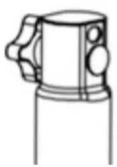
ASSEMBLY
text_image
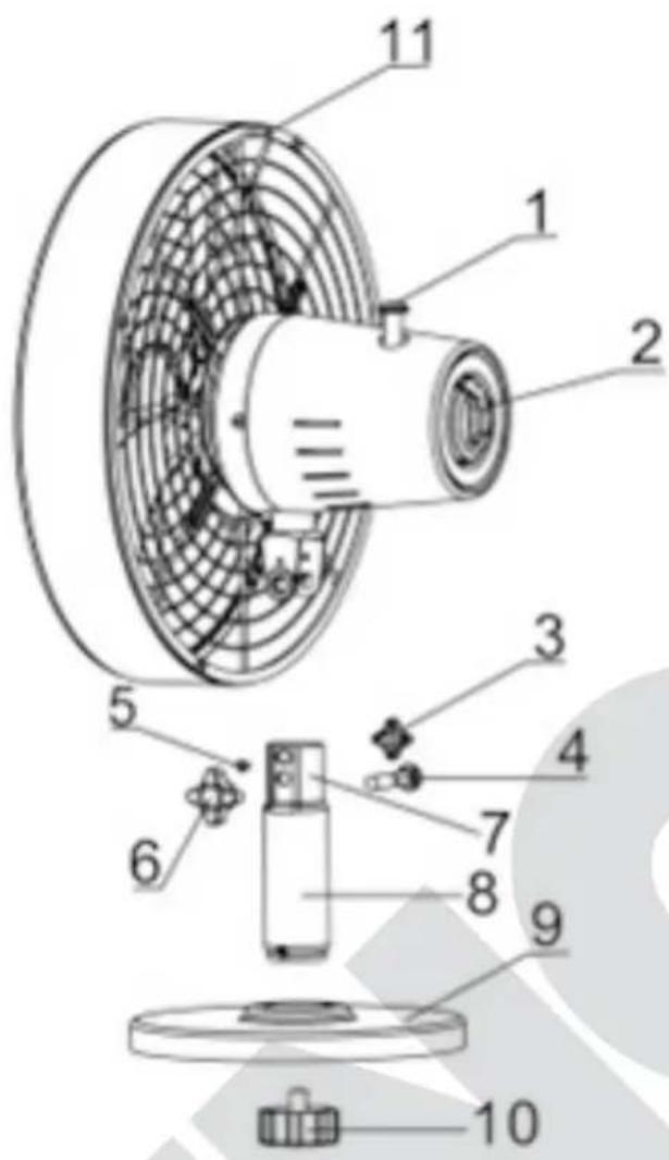
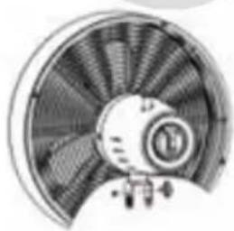
Technical diagram of a fan assembly with numbered components for identification1 Oscillation button
2 ON/OFF/Speed
3 | Lock nut for the tilt angle
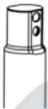
4 Attachment bolt motor/tube
5 Fasten ing pin
6 Loc k nubtor/tub e
7 | Tside of bleu
8 T | ube
9 | sea
10 | Screw of base fastener
11 | Carryg handle
- Prior to assembly, make sure that you are installing the appliance in a flat and dry location.
- Remove all packaging materials and any transport guards and stickers (not the type plate or the serial number!). Keep the packaging material away from children. Choking hazard! If necessary, dispose of the packaging material according to the applicable statutory waste disposal regulations. Tip: Keep the packaging material in case you wish to return the appliance for repairs at a later time.
-
Inspect the appliance for damage. If there is visible damage, do not operate the appliance; instead, contact our Customer Service department.
-
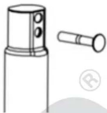
Check whether all required parts listed in this manual have been shipped with your appliance. Notice: If it is still fitted on the axle, you can remove the fabric tube as it merely serves as protection during transport.
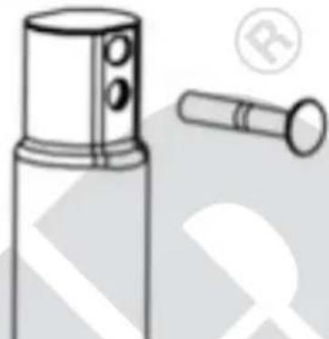
- Loosen the attachment screw and nut from the top of the tube.
- Remove the screw of the base fastener from the bottom of the tube.
natural_image
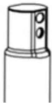
Line drawing of a mechanical device with handle and base (no text or symbols)
natural_image
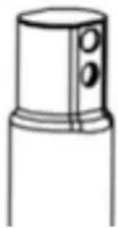
Simple line drawing of a cylindrical object with a lid and two circular ports (no text or symbols)
-
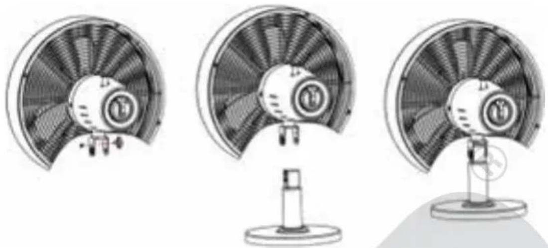
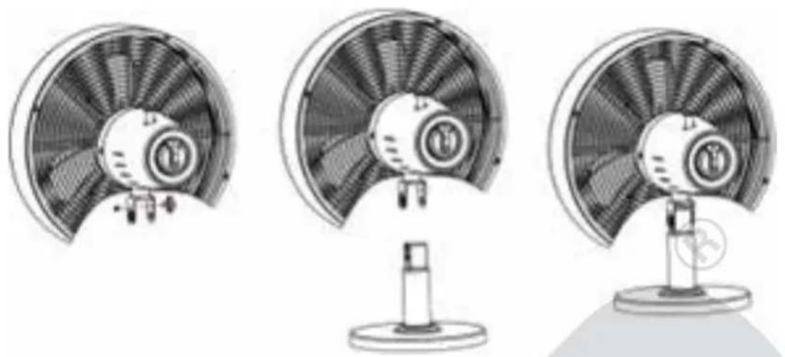
Insert the tube into the recess at the top of the base and turn both over while holding these parts in place to gain access to the bottom.
-
Align the screw of the base fastener as shown in the opening of the base. Tighten the screw to attach the base to the fan housing.
natural_image
Technical line drawing of three mechanical components with no visible text or symbols-
Now, turn the base with the stand pipe over again and place the base on a flat, and stable surface.
-
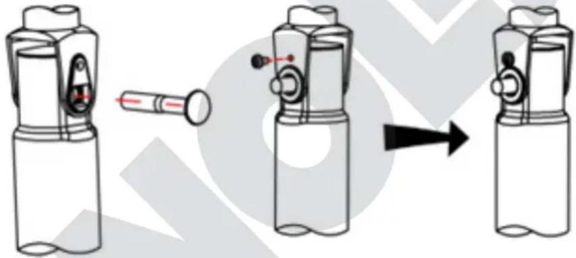
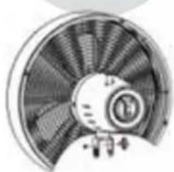
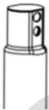
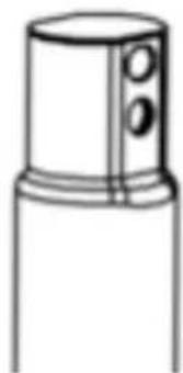
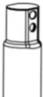
Remove locking screw No. 3 from the motor unit. Next, place the motor unit on the tube, making sure the openings on the hinge bracket are aligned with the slots on the tube:
natural_image
Line drawing of a mechanical device with handle and base (no text or symbols)
natural_image
Simple line drawing of a cylindrical object with a side port and two circular holes (no text or symbols)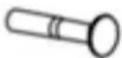
natural_image
Three technical illustrations of a fan with internal blades and a stand, shown from different angles (no text or symbols present)- Feed attachment bolt No. 4 through both openings. Insert fastening pin No. 5 into the opening above the attachment bolt to secure the parts.
natural_image
Diagram showing a device being processed from a cylindrical component, with no visible text or symbols.- Attach lock nut No. 6 to the protruding side of attachment bolt No. 4 and tighten the nut.
- On the other side, tighten locking screw No. 3 on the protruding side of the fastening pin.
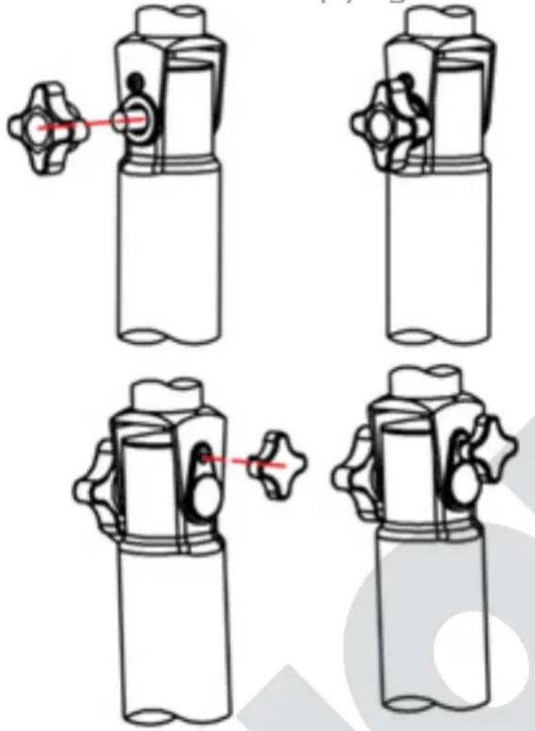
- You can now adjust the inclination of the motor unit by slightly loosening locking screw No. 3 and aligning the motor unit at the desired angle before fixing the motor unit in place again by tightening the locking screw (please see picture next side).
natural_image
Four technical line drawings of a mechanical device with no visible text or symbolsOPERATION
- Make sure that the appliance is set up in a secure and stable manner on a suitable and level surface.
- Place the plug in a power socket (220–240 V AC\~, 50 Hz).
- The appliance must not be set up in bathrooms or other wet environments!
- If you wish to set up the appliance in another location, turn off the appliance first before disconnecting the plug from the power socket.
- Do not stick any objects into the appliance.
Adjusting the tilt angle
- You can tilt the motor housing vertically to some extent. To do so, slightly loosen the lock nut for the tilt angle, bring the motor housing to the desired position, and tighten the nut again.
Selecting the speed
- Turn on the appliance by selecting one of the three speed levels on the rotary switch (No. 2):
■ Level "1": light breeze
■ Level "2": medium breeze
■ Level "3": strong breeze
■ Level "0" turns off the appliance.
- You can switch between the different speed levels at any time.
Swivel function/oscillation
-
Press the oscillation button on the appliance head down. The appliance will now swivel by itself.
-
If you wish to turn off the swivel function again, pull the oscillation button up.
Power off
- Turn the rotary switch to "O" to switch the appliance off. Disconnect the plug from the power socket if you no longer use the appliance.
CLEANING AND CARE
Switch off the appliance by turning the rotary switch to "O" and unplug the appliance from the power socket.
Wait until the appliance has come to a complete stop.
Make sure never to immerse the appliance in water. Do not expose the motor and electrical components to moisture.
- Never use scouring agents, steel wool, metal objects, hot cleaners or disinfectants.
- Wipe off the stand tube and grille with a slightly damp cloth.
natural_image
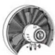
Two identical views of a desktop fan with visible blades and mounting base (no text or symbols)- You can clean the fan wheel by loosening the small screw on the basket grille and removing the front half of the basket. Carefully clean the fan wheel with a soft cloth and properly screw all parts back together again.
- Store the fan in a dry, safe place to protect it from dust, impacts, heat and moisture.
GUARANTEE CONDITIONS
We grant a 24 months guarantee, and in case of commercial use a 12 months guarantee, starting from the date of purchase for any damage demonstrably due to manufacturing defects and when the appliance has been used according to its intended use. Within the warranty period we will remedy defective materials or workmanship through repair or replacement, at our option. Our warranty terms apply only to appliances sold in Germany and Austria. For other countries, please contact the responsible importer. In the event of a claim for remedy of defects, please send the appliance to our after sales service, properly packaged, together with a copy of the automatically generated sales receipt, which must show the date of purchase, and a description of the defect. You can print out a return receipt on our website https://unold.de/pages/rucksendungen. (only for entries from Germany and Austria). The warranty does not cover damage from normal wear, improper handling and failure to comply with the maintenance and care instructions. The warranty is void if repairs or modifications are made to the appliance by third parties. Any claims of the end consumer vis-à-vis the retailer are not limited by this warranty.
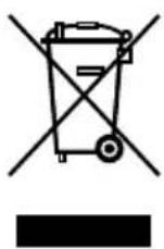
WASTE DISPOSAL / ENVIRONMENTAL PROTECTION
Our appliances are produced on a highquality level for a long lifetime. Regular maintenance and expert repairs by our after-sales service can extend the useful life of the appliance. If an appliance is defective and repair is not possible, we ask you to follow the following instructions for disposal. Do not dispose this appliance together with your standard household waste. There is a legal requirement to dispose of waste electrical and electronic equipment (WEEE) as well as batteries and accumulators separately from household waste. You can recognise this waste equipment by the crossed-out wheeled bin symbol (WEEE symbol). Please bring this product to an approved collection point for recycling of electric and electronic products. By separate collection and disposal of waste products you help to protect natural resources and ensure, that the product is disposed in an adequate way to protect health and environment.
NOTICE D'UTILISATION MODÈLE 86715
SPÉCIFICATION TECHNIQUE
Puissance : 35 Watts, 220–240 V\~, 50 Hz
Dimensions : Env. 33,5 x 23 x 47,5 cm (p/l/h)
Poids : Env. 3,1 kg
Diamètre : 33 cm
text_image
Technical diagram of an air conditioner fan with numbered parts for identificationnatural_image
Line drawing of a mechanical device with handle and base (no text or symbols)
natural_image
Technical line drawing of a cylindrical device with a flanged handle and a separate cylindrical component (no text or symbols)natural_image
Technical line drawing of a mechanical component with a central shaft and circular base (no text or symbols)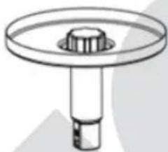
natural_image
Technical line drawing of a mechanical component with a central hub and circular top (no text or symbols)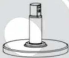
natural_image
Simple line drawing of a cylindrical object mounted on a circular base (no text or symbols)natural_image
Line drawing of a mechanical device with handle and cylindrical body (no text or symbols)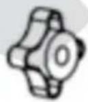
natural_image
Simple line drawing of a cylindrical object with two circular holes, resembling a mechanical or electronic component (no text or symbols)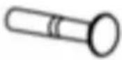
natural_image
Technical illustration of a fan or turbine blade assembly (no text or symbols visible)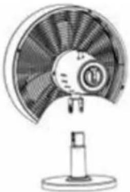
natural_image
Line drawing of a desktop fan with visible blades and base (no text or symbols)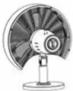
natural_image
Illustration of a desktop fan with visible blades and base (no text or symbols)Copyright UNOLD AG | www.unold.de
natural_image
Diagram showing a device being processed from a cylindrical component, with no visible text or symbols.natural_image
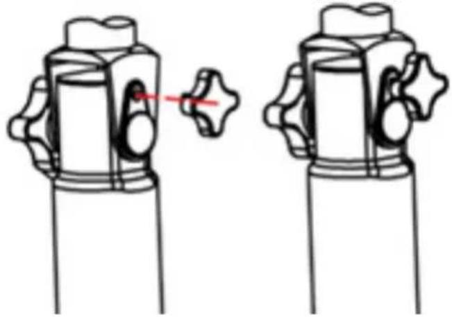
Two identical mechanical valve diagrams with a red pointer indicating the valve position (no text or symbols)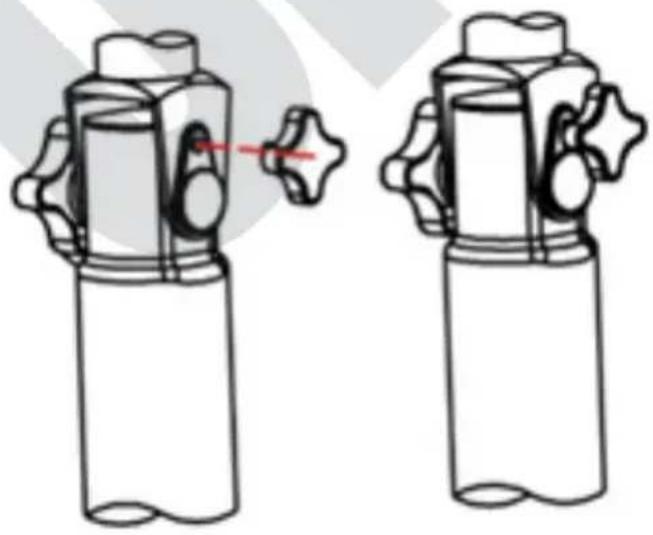
natural_image
Diagram of two identical mechanical components with no text or symbols, showing a close-up and a red arrow indicating rotation (no text or symbols present)UTILISATION
natural_image
Two views of a desktop fan with visible blades and mounting base (no text or symbols)CONDITIONS DE GARANTIE
text_image
Technical diagram of a fan or fan assembly with numbered components for identificationnatural_image
Line drawing of a mechanical device with handle and base (no text or symbols)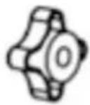
natural_image
Simple line drawing of a cylindrical object with a top and side ports (no text or symbols)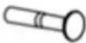
natural_image
Technical line drawing of a mechanical component with a cylindrical shaft and circular base (no text or symbols)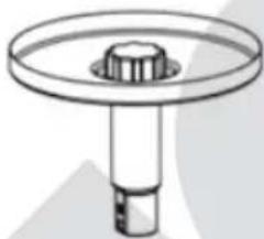
natural_image
Technical line drawing of a mechanical component with a central hub and circular top (no text or symbols)
natural_image
Simple line drawing of a cylindrical object mounted on a circular base (no text or symbols)natural_image
Line drawing of a mechanical device with handle and mounting base (no text or symbols)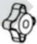
natural_image
Simple line drawing of a cylindrical object with a side protrusion and two circular holes (no text or symbols)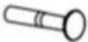
natural_image
Technical line drawing of a mechanical component with no visible text or symbols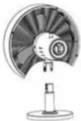
natural_image
Line drawing of a desktop fan with a circular blade and stand (no text or symbols)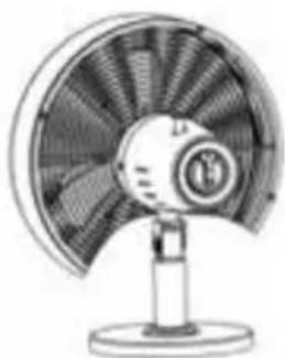
natural_image
Illustration of a desktop fan with visible blades and mounting base (no text or symbols)natural_image
Diagram showing a device being processed from a cylindrical component, with no visible text or symbols.text_image
Technical diagram showing four stages of a valve mechanism with red alignment arrows indicating movement or adjustment.BEDIENING
natural_image
Two views of a desktop fan with visible blades and mounting base (no text or symbols)text_image
Technical diagram of a fan assembly with numbered components for identificationnatural_image
Technical line drawings of mechanical components including a cylindrical device, a hexagonal nut, and a cylindrical tool (no text or symbols)natural_image
Technical line drawings of three mechanical components with no visible text or symbolsnatural_image
Technical line drawings of mechanical components including a cylindrical device, a gear-like component, and a cylindrical tool (no text or symbols)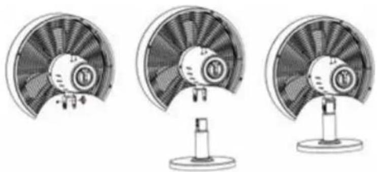
natural_image
Three technical illustrations of a fan with visible blades and mounting base (no text or symbols)natural_image
Diagram showing a device being processed from a cylindrical component, with no visible text or symbols.natural_image
Diagram of two identical cylindrical containers with a valve, shown from different angles (no text or symbols)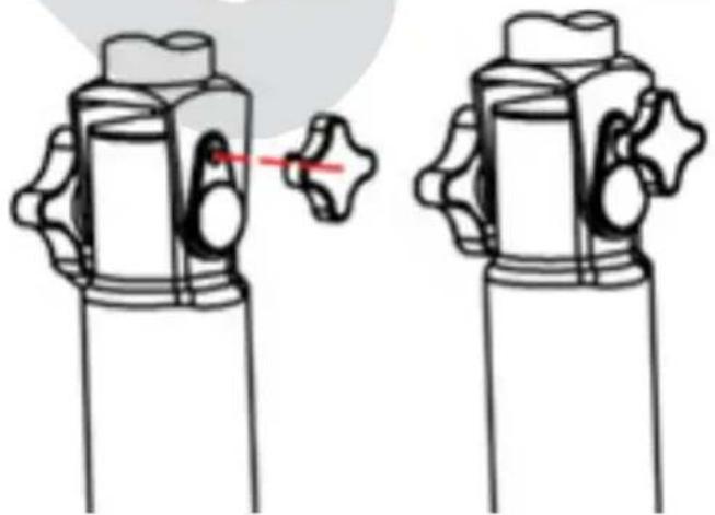
natural_image
Illustration of two identical mechanical components with no text or symbols, showing a change in the shape between them (no text or symbols present)USO DELL'APPARECCHIO
natural_image
Two views of a desktop fan with visible blades and mounting base (no text or symbols)text_image
Technical diagram of an air conditioner fan with numbered parts for identificationnatural_image
Line drawing of a mechanical device with handle and base (no text or symbols)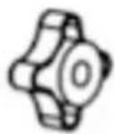
natural_image
Simple line drawing of a cylindrical object with a side port and two circular ports (no text or symbols)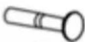
natural_image
Technical line drawing of a mechanical component with a circular top and cylindrical base (no text or symbols)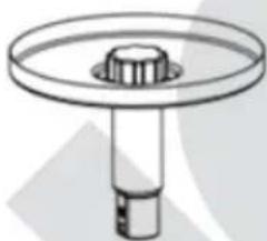
natural_image
Technical line drawing of a mechanical component with a central hub and circular top (no text or symbols)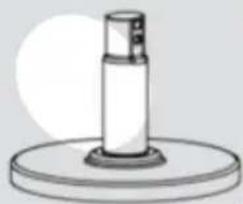
natural_image
Simple line drawing of a cylindrical object mounted on a circular base (no text or symbols)natural_image
Line drawing of a mechanical device with handle and mounting base (no text or symbols)
natural_image
Simple line drawing of a cylindrical object with two circular holes, resembling a stylized lamp or connector (no text or symbols)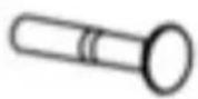
natural_image
Illustration of a desktop fan with a stand (no text or symbols)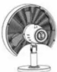
natural_image
Illustration of a desktop fan with visible blades and central hub (no text or symbols)text_image
Diagram illustrating the process of a device with a pen, showing step-by-step assembly from left to right.natural_image
Two identical line drawings of a valve mechanism with a red pointer, no text or symbols present.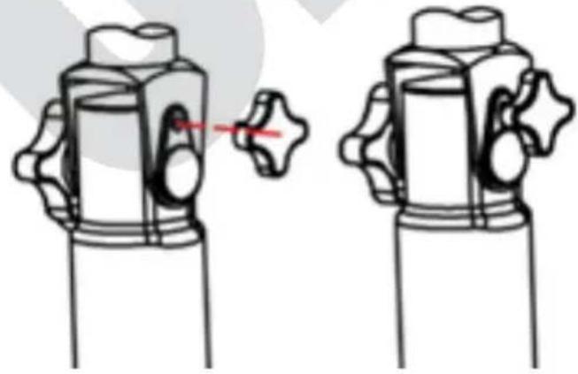
natural_image
Diagram of two mechanical components with no visible text or symbolsMANEJO
natural_image
Two views of a desktop fan with visible blades and mounting base (no text or symbols)text_image
Technical diagram of a fan assembly with numbered parts for identificationnatural_image
Line drawing of a mechanical device with handle and base (no text or symbols)
natural_image
Illustration of a cylindrical device with a side-mounted sensor and a separate cylindrical component (no text or symbols)natural_image
Technical line drawing of a mechanical component with a cylindrical shaft and circular base (no text or symbols)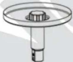
natural_image
Technical line drawing of a mechanical component with a central hub and cylindrical shaft (no text or symbols)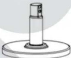
natural_image
Simple line drawing of a cylindrical object mounted on a circular base (no text or symbols)natural_image
Line drawing of a mechanical device with handle and base (no text or symbols)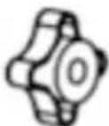
natural_image
Simple line drawing of a cylindrical object with a side tab and two circular holes (no text or symbols)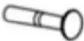
Copyright UNOLD AG | www.unold.de
natural_image
Three technical illustrations of a fan with internal blades and a stand, shown from different angles (no text or symbols present)natural_image
Diagram showing a device being processed from a cylindrical component, with no visible text or symbols.natural_image
Technical line drawing of two mechanical components with a red pin indicating a joint or connection (no text or symbols present)