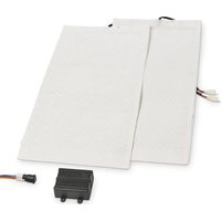
MagicComfort MSH 301 - Heating DOMETIC - Free user manual and instructions
Find the device manual for free MagicComfort MSH 301 DOMETIC in PDF.


| Product type | Seat heating (retrofit kit) |
| Brand | Dometic |
| Model | MagicComfort MSH 301 |
| Product number | 9600000396 |
| Operating voltage | 12 V== (DC) |
| Power | Adjustable in 3 levels: from 10 to 70 watts per seat |
| Max. current consumption | 5 A |
| Dimensions (seat element) | 580 x 270 mm |
| Dimensions (backrest element) | 580 x 270 mm |
| Number of levels | 3 (high, medium, low) |
| Intended use | Installation in front seats of passenger cars, vans and motorhomes |
| Delivery contents | Heating elements (seat and backrest), switch, cable harness, control box, drilling template, double-sided adhesive tape, insulating materials, operating manual |
| Operation | Control via switch with LED indicators (3 LEDs for level 3, 2 for level 2, 1 for level 1) |
| Safety | Do not use if wet; do not place sharp/heavy objects; for people sensitive to heat, use only level 1; do not cover with blankets |
| Warranty | According to applicable legislation (legal warranty period) |
| Maintenance | Clean with a damp cloth; avoid spilling liquids; do not switch on if wet |
| Repairability | Contact the manufacturer or a specialized dealer; enclose invoice and description of the defect |
Frequently Asked Questions - MagicComfort MSH 301 DOMETIC
User questions about MagicComfort MSH 301 DOMETIC
0 question about this device. Answer the ones you know or ask your own.
Ask a new question about this device
Download the instructions for your Heating in PDF format for free! Find your manual MagicComfort MSH 301 - DOMETIC and take your electronic device back in hand. On this page are published all the documents necessary for the use of your device. MagicComfort MSH 301 by DOMETIC.
USER MANUAL MagicComfort MSH 301 DOMETIC
Installation and Operating Manual. 9
Please read this instruction manual carefully before installation and first use, and store it in a safe place. If you pass on the product to another person, hand over this instruction manual along with it.
Contents
1 Explanation of symbols 10
2 Safety and installation instructions 10
3 Scope of delivery 13
4 Intended use 13
5 Technical description 14
6 Installing the seat heater 14
7 Using the seat heater 18
8 Guarantee 19
9 Disposal. 19
10 Technical data 19
1 Explanation of symbols

WARNING!
Safety instruction: Failure to observe this instruction can cause fatal or serious injury.

NOTICE!
Failure to observe this instruction can cause material damage and impair the function of the product.

NOTE
Supplementary information for operating the product.
2 Safety and installation instructions
Please observe the prescribed safety instructions and stipulations from the vehicle manufacturer and service workshops.
The manufacturer accepts no liability for damage in the following cases:
- Faulty assembly or connection
- Damage to the product resulting from mechanical influences and excess voltage
- Alterations to the product without express permission from the manufacturer
- Use for purposes other than those described in the operating manual

NOTICE!
To prevent the risk of short circuits, always disconnect the negative terminal of the vehicle's electrical system before working on it. If the vehicle has an additional battery, its negative terminal should also be disconnected.

WARNING!
Inadequate supply cable connections could result in short circuits, which could have as a consequence that:
- Cable fires occur
- The airbag is triggered
- Electronic control devices are damaged
- Electric functions fail (indicators, brake light, horn, ignition, lights)
Please observe the following instructions:
-
When working on the following cables, only use insulated cable lugs, plugs and flat push-on receptacles:
-
30 (direct supply from positive battery terminal)
- 15 (connected positive terminal, behind the battery)
- 31 (return cable from the battery, earth)
Do not use terminal strips.
- The safest type of connection is to solder the ends of the cables together and then insulate them.
Only use insulated cable terminals, plugs and flat sockets for releasable connections. Do not use crimp terminals (cable connectors) or terminal strips.
- Use a crimping tool (fig. 1 10, page 3) to connect the cables.
-
When connecting to cable 31 (earth), screw the cable
-
To the vehicle's earth bolt with a cable lug and a gear disc or
- To the sheet-metal bodywork with a cable lug and a self-tapping screw.
Ensure that there is a good earth connection.
If you disconnect the negative terminal of the battery, all data stored in the volatile memories will be lost.
-
The following data must be set again, depending on the vehicle equipment options:
-
R a d i o c o d e
- Vehicle clock
- T i m e r
- On-board computer
- Seat position
You can find instructions for making these settings in the appropriate operating instructions.
Observe the following installation instructions:
- Secure the parts installed in the vehicle in such a way that they cannot become loose under any circumstances (sudden braking, accidents) and cause injuries to the occupants of the vehicle.
- To prevent damage, when drilling ensure that there is sufficient space on the other side for the drill head to come out (fig. 2, page 4).
- Deburr all drill holes and treat them with a rust-protection agent.
Observe the following instructions when working with electrical parts:
- When testing the voltage in electrical cables, only use a diode test lamp (fig. 1 8, page 3) or a voltmeter (fig. 1 9, page 3).
Test lamps with an illuminant (fig. 12, page 3) take up voltages which are too high and which can damage the vehicle's electronic system.
-
When making electrical connections (fig. 3, page 4), ensure that
-
They are not kinked or twisted
- They do not rub on edges
-
They are not laid in sharp-edged ducts without protection.
-
Insulate all connections.
-
Secure the cables against mechanical wear with cable binders or insulating tape, for example to existing cables.
Observe the following instructions when using the seat heater:
- Do not place any sharp or heavy objects on the seat, as the seat heater could otherwise be damaged.
- Persons with an impaired sensitivity to heat should only operate the seat heating on level 1.
- Do not place any heat insulating objects, such as blankets or coats, on the seat when the seat heater is switched on.
- The seat heater can be damaged by fluids spilt on the seat.
- Never switch the seat heater on when it is wet.
3 S C O P E O F D
| No. in fig. 4, page 4 | Quantity Designation Ref. no. | ||
| MSH300 MSH301 | |||
| 1 2 1 Seat surface heating element 9101700038 | |||
| 2 2 1 Backrest heating element 9101700039 | |||
| 3 2 1 Switch 9101700041 | |||
| 4 1 | 1 Set of connecting cables | (black: right side | 9101700053 |
| blue: left side) | |||
| 5 1 | 1 Switchbox | 9101700051 | |
| - | 1 | 1 Drill template | |
| - | 12 | 6 | Double-sided adhesive tape |
| - | 12 | 6 | Insulating material |
| - | 1 | 1 Operating manual | |
4 Intended use
The MagicComfort seat heating MSH300 (ref. no. 9600000395) and MSH 301 (ref. no. 9600000396) are suitable for installation in the front vehicle seats of passenger vehicles, transporters and caravans.

NOTICE!
For vehicles equipped with side airbags in the seat backrests, seat occupancy detection or child seat detection, observe the vehicle manufacturer's specifications.
5 Technical description
The heating elements for the MagicComfort seat heating MSH300 and MSH301 can be installed in the driver's seat and in the passenger seat.
The shape of the seat is not altered by the heating elements.
The seat heater is operated using a switch.
6 Installing the seat heater
6.1 Tools required (fig. 1, page 3)
For installation and assembly you will need the following tools:
- Drill bit set (1)
- Drill (2)
Screwdriver (3) - Set of ring or open-ended spanners (4)
- Measuring ruler (5)
- Hammer (6)
- Centre punch (7)
To make and test the electrical connection, the following tools are required:
- Diode test lamp (8) or voltmeter (9)
Crimping tool (10)
Insulating tape (11)
Hot air blower (13)
Soldering iron (14)
Solder (15) - Cable bushing sleeves (if necessary)
To fasten the cables you may require additional cable binders.
6.2 Installing the seat heater
Removing the seat
Secure the vehicle against rolling away.

NOTICE!
For vehicles with side air bags in the seat backrest, observe the manufacturer's instructions on removing the seats and the upholstery.
Check the suitability for installation using these installation instructions and the manufacturer's information.
Remove the fastening screws from the vehicle seat.
Lift the seat out of the vehicle.
Preparing the seat
Remove all plastic panelling from the seat to ensure the fastening of the cover fabric can be reached.
Separate the backrest from the seat (fig. 7, page 5 and fig. 8, page 5).
Open the seat cover on the seat surface.
The cover fabric is usually tucked into a seam on the frame with a wide cardboard strip or metal wire.
Remove the fasteners using a screwdriver and pliers (fig. 9, page 5 and fig. 10, page 5).
Remove any upholstery staples or cross braces (fig. 11, page 5).
Open the cover of the backrest in the same way.
Preparing the heating elements

NOTICE!
Insulate all the trimmed ends with the insulating material supplied to prevent a short circuit.

NOTE
-
You can cut the heating elements to the required length and shorten the lengths of the two conductor paths.
-
You can cut out a section of the heating element in the area of the anchoring grooves on the seat or the backrest. Make sure the cut-out sections are only made between the two black seams (fig. 5, page 4).
-
Do not cut the mat lengthways, otherwise it will not be heated in the area of the incision (fig. 5, page 4).
-
The heating surface on the backrest only needs to extend approx. 30 - 35 ~cm above the seat, as the driver only leans against this area when sitting normally (fig. 6, page 4).
Place the heating elements on the seat and backrest.
If there are anchoring grooves in the seat or the backrest, mark these areas on the heating elements.
Mark the required lengths. Take into account the depth of the anchoring grooves, if present. The heating element is inserted in these anchoring grooves.
Trim the heating element to the required length.
Customise the cut-out sections as required.
Insulate all the trimmed ends with the insulating material.
Installing the heating element for the seat surface
Insert the heating element for the seat surface between the cover fabric and the foam core of the seat (fig. 12, page 5).
If anchoring grooves are present, make sure that the cut-out sections are positioned over the anchoring grooves (fig. 13, page 5) and place the heating elements in the anchoring grooves.
Fasten the heating element using double-sided adhesive tape to prevent it sliding on the foam core.
Ensure that no creases or kinks form.
Installing the heating element for the backrest

NOTICE!
If the seats are equipped with side airbags, then there is a predetermined breaking point in the cover fabric. The seat cover must therefore not be pulled tightly or slip out of place.
Open the lower area of the backrest cover (fig. 14, page 5).
Push the heating element into the gap between the seat cover and the seat cushion (fig. 15, page 5).
Fasten the heating element using double-sided adhesive tape to prevent creases.
Installing the seat
Reassemble the backrest and seat.
Lift the seat into the vehicle.
Secure the vehicle seat with the fastening screws.
Electrical connection
MSH300
The complete circuit diagram can be found in fig. 18, page 6.
MSH301
The complete circuit diagram can be found in fig. 19, page 7.

NOTICE!
Ensure it has been securely fitted, particularly in the area of the seat rails.
Attach the switchbox to a suitable location in the vicinity of the dashboard (fig. 20, page 8).
Find a suitable place for installing the seat heater switch.
If possible, use the blanking plugs provided for this purpose.
Ensure that there is enough room behind the panel for the installation of the switch.
Mark the switch cut-out using the template provided (fig. 21, page 8).
Cut out the marked area with an appropriate tool.
Install the switch into the cut-out (fig. 16, page 5).
Install the ready-made wiring harness so that the cables cannot bend or fray (fig. 17, page 5).
7 Using the seat heater

NOTE
The seat heating logo (fig. 22 1, page 8) also lights up when the seat heating is switched on.
Press the seat heater switch to turn on the seat heater:
- Press once: Level 3 (high heat output)
- Press twice: Level 2 (medium heat output)
- Press three times: Level 1 (low heat output)
One, two or three LEDs (fig. 22 2, page 8) on the switch light up in red.
To switch the seat heating off: Press the switch until the LEDs (fig. 22 2, page 8) on the switch go out.
8 G u a r a n t e e
The statutory warranty period applies. If the product is defective, please contact the manufacturer's branch in your country (see the back of the instruction manual for the addresses) or your retailer.
For repair and guarantee processing, please include the following documents when you send in the device:
- A copy of the receipt with purchasing date
- A reason for the claim or description of the fault
9 D i s p o s a l
Place the packaging material in the appropriate recycling waste bins wherever possible.
If you wish to finally dispose of the product, ask your local recycling centre or specialist dealer for details about how to do this in accordance with the applicable disposal regulations.
10 Technical data
| MagicComfort MSH300 | MagicComfort MSH301 | |
| Ref. no.: 9600000395 9600000396 | ||
| Operating voltage: 12 V== | ||
| Power: | adjustable to three levels, with 10 – 70 W per seat | |
| Max. power consumption: | 10 A | 5 A |
| Dimensions: | Seat element: 580 x 270 mm Backrest element: 580 x 270 mm | |
5 Description technique
HarpBaTeNbHbIe 3nEmeHTbI He n3MeHraOT φopMy cndeHn.
YnpabHeHne o6oRpeBOM cnDeHn OcUeCTBnEeTc BbIKIouaTeHem.
6 MoHTax KOMPJIeKta o6OrpeBa cndeHn
6.1 Tpe6yembI INHcTpymeHT (pnc. 1, ctp. 3)
Дя yctaHOBKN mOHTaxa Tpe6yeTcS cIeIyUoI INHCTpyMeNT:
-
Komпент Севр (1)
-Дрени (2)
-OTBepTKa (3) -
KomnneKT haKnaHbIX nII IN poXKObIX raeuHbIX KInOuei (4)
-Пинейка (5) - Monotok (6)
- Kephep (7)
MoHTaK HaIpeBaTeJIbHOrO 3JIeMeHtA Hn3a CnIeHbY
BctaBbTe HarpBeBaTeIbHbI eIeMeHT Hn3a CnIeHbI MExy O6NBKO I neHONPnactOM (pnc. 12, ctp. 5).
Ecnn nmeotc yrny6neHna: Cneinte 3a TeM, YTObI Bbpe3bI HaxOINncb HaD yrny6neHnMa (pnc.13, ctp.5) n ynoxte HarpeBaTeNbHbIe 3JIemEnT B yrrny6neHnra.
3aKpeNITE HaRpeBaTeBbHbI 3nemeHT OT CMeUeHnI NO NeHOnPnAcTy, NcNoB3yA DByXCTOpOHnIO KNeKyIO nEHTy. CneDInTe 3a TeM, YTO6bI OHN O6pa3OBbIBaINCb CKNaDK NII IN I3nOMbl.
MOHTaK HaFpeBaTeJIbHOrO 3JIeMeHTa CINHHKIn

BHHMAHNE!
EcnncndeHbOcHaueHb6OKOBIMN NOyUKMn 6e3OpacHOCTN,TO 0NBka nMeet Mecta 3anporpaMMNPOBaHHOro pa3pyueneHn. IOnToMy 3anpeaetcra CnHKOM CNIbHO HATrINBaTb INN CMeuaTb O6NBky.
PackpoIte o6nBky cnnHKn B HnXHei qactn (pnc. 14, ctrp. 5).
Bctabte HarpeBaTeIbHbI eIeMeHT B IonoCTb MeJy O6NBKOI n NeHONnactOM (pnc. 15, ctp. 5).
3aФИКСИРУTe HaIpeBaTeIbHbI ΘIeMENT IByXCTOpOHHeN KNeIKOJI NeHTOJ TaK, YTO6bl He O6pa3OBbIBaIIncsCKnAdkn.
MOnTaJcNJaHbI
Co6epnte cHky nNoDyUkcy cndeHb.
BCTaBbTe cHHeB aBTOMO6nIb.
3aKpeHnTe cndeHbe KpeNexHbIMN BnHTaMn.
ПоДКЛЮЧЕНС ΚΙЕΚΤΡΗΥΕΝΚΟ ΧΕΤΗ
MSH300
O6uaa cxema coeHneHn npBedeHa Ha pnc. 18, ctp. 6.
MSH301
O6uaa cxema coeHneHn npBedeHa Ha pnc. 19, ctp.7.

BHIMAHHE!
Oco6oe BnImaHne 6e3oNaChOCTN HnAedXHOCTN npOKnaDKn o6paaTe B 3OHe HnPaBnIooNX CnDeHbJ.
3aKpeNITe KOMMyTaUHOHHbI 6nOK B NOxOJIeM MeCTe B 30He NaHEni np6OpOB (pnc.20, ctp.8).
HaIINTe IOxOJIe MeCTO MOHTaJa BbIKIOUaTeJIa O6OrpeBa CnDEHNI. Pn BO3MOXHOCTN, INcONb3yIte InJ 3TOI O IMEIOUInecr 3aIpyuKN.
y6eINTEcB B TOM, yTO 3a O6uNbKOJ UMeETcA DOCTaTOUHO MeCTa IJIa MOHTaJa BBKIIIOUaTeTn.
Pa3MeTbTe Bblpe3 dIy BblKnIOuAteIeN C NOMOUIIO npINaeroMOro Ia6NoHa (pnc. 21, ctp. 8).
BbipexbTe pa3MeueHHyIO 6nactb COOTBeTCTByIOuIM INHCTpyMeHTOM.
YcTaHOBInTe BbIKIOuAteIb B Bblpe3 (pnc. 16, ctp. 5).
ПрохиTe NOД�TOBнБИй XГуТ Ka6eNeI TaK, YTO6bI npeDToBpaTITb Ixпери6 ИИnpOTnPaHne (pnc. 17, ctp. 5).
7 Исторьанne oborpeba cndeHn

YKA3AHNE
Iorotn o6oRpeBa cndeHn (pnc. 22 1, ctp. 8) 3aropaeTcN I B Tom cnyuae, ecnn o6oRpeB cndeHn BbIKIOueH.
ДяВКПIOUeHЯOBorpeBa cndeHn HaxMnte BbIKIQUaTeIb O6OrpeBa cndeHn:
- HaxaTb OINH pa3: cTypeHb 3 (cInbHbI o6orpeB)
- HaxaTb Dba pa3a: cTypeHb 2 (cpeHn o6orpeB)
- HaxaTb Tpr pa3a: cTypeHb 1 (cna6bI o6orpeB)
√ OdINH, IBa IIa Tprn CBeToAnOda (pnc. 22 2, ctp. 8) Ha BbIKIouaTeNe roprKpaChbIM.
Дя Вькноуеня оборpeва сидан: Habимаite Вькноуател do tex nop, noka CBetoДиОды (pnc. 2 2,ст. 8) Na Вькноуате He norachyT.
8 rapaHTn
IeJCTBNTeHn yCTaHOBnEHnBn 3aKoHOM cPOK rapaHTn. Ecnn npOdyKT HeNCnPpBeH,
6paTntecb B npeDCTaBNTeJIbCTBO n3rOToBNTeN B BaSei cTpaHe (aDpeca cm. Ha
OBopOTHO CTOpOHe IHCTpyKuN) INN B TOPOBYIO OprAHn3aUIO.
B uejx npoBeHnra pemOnTa nnn rapaHTnHoro o6cnyXnBaHnry BbldoJXhbl taKxe nocnA Tb cneDyUOuine DOkymeHTbl:
- KONNU CyeTa C DaToI NOKyNkN,
- npuHny peKnaMaunn nn OncnpaBHOCTn.
9 Y T N I N 3 a u
IIO BO3MOXHOCTN, BbIKnIbIbAaIte yNaKOBOUHbI MaTePnaI B MyCOp, NOIeXaIINBTOpHuOH nepepa6oTKe.
EcnBbIOKOHaTeIbHO BbIOAnTe npOdyKT n3 3KcPnyatauIN,TO NOnyUHTe INOpMaunIO B6nXaMWeM ueHpe NO BTOpNHyo nepepa6OTKe INN B TOPOBOI CETNO COOTBeTCTByOux PpeDnCaHnx PO yTNn3aUN.
10 Texnueckne daHHbIe
dometic.com/sales-offices

- Please read this instruction manual carefully before installation and first use, and store it in a safe place. If you pass on the product to another person, hand over this instruction manual along with it.
- Contents
- Explanation of symbols
- WARNING!
- NOTICE!
- NOTE
- Safety and installation instructions
- Please observe the prescribed safety instructions and stipulations from the vehicle manufacturer and service workshops.
- Observe the following installation instructions:
- S C O P E O F D
- Intended use
- Technical description
- Installing the seat heater
- Tools required (fig. 1, page 3)
- Installing the seat heater
- Removing the seat
- Preparing the seat
- Preparing the heating elements
- Installing the heating element for the seat surface
- Installing the heating element for the backrest
- Installing the seat
- Electrical connection
- MSH300
- MSH301
- Using the seat heater
- G u a r a n t e e
- D i s p o s a l
- Technical data
- Description technique
- MoHTax KOMPJIeKta o6OrpeBa cndeHn
- Tpe6yembI INHcTpymeHT (pnc. 1, ctp. 3)
- MoHTaK HaIpeBaTeJIbHOrO 3JIeMeHtA Hn3a CnIeHbY
- MOHTaK HaFpeBaTeJIbHOrO 3JIeMeHTa CINHHKIn
- BHHMAHNE!
- MOnTaJcNJaHbI
- ПоДКЛЮЧЕНС ΚΙЕΚΤΡΗΥΕΝΚΟ ΧΕΤΗ
- BHIMAHHE!
- Исторьанne oborpeba cndeHn
- YKA3AHNE
- rapaHTn
- Y T N I N 3 a u
- Texnueckne daHHbIe
Brand : DOMETIC
Model : MagicComfort MSH 301
Category : Heating