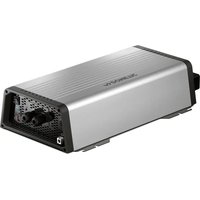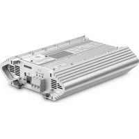
MT BCB1010 - Battery charger DOMETIC - Free user manual and instructions
Find the device manual for free MT BCB1010 DOMETIC in PDF.


User questions about MT BCB1010 DOMETIC
0 question about this device. Answer the ones you know or ask your own.
Ask a new question about this device
Download the instructions for your Battery charger in PDF format for free! Find your manual MT BCB1010 - DOMETIC and take your electronic device back in hand. On this page are published all the documents necessary for the use of your device. MT BCB1010 by DOMETIC.
USER MANUAL MT BCB1010 DOMETIC
EN Battery control booster
Batterikontroll-booster
© 2022 Domatic Group. The visual appearance of the contents of this manual is protected by copyright and design law. The underlying technical design and the products contained herein may be protected by design, patent or be patent pending. The trademarks mentioned in this manual belong to Domatic Sweden AB. All rights are reserved.
1
2

11
| EN DE FRIT NL DA SV NO | |||||||
| rd Red Rot Rouge Rosso Rood Rcd Rcd Rcd | |||||||
| bk Black Schwarz Noir Nero Zwart Sort | Svart Svart |
| EN DE FRIT NL DA SV NO | |||||||
| rd Red Rot Rouge Rosso Rood Rrod Rrod | |||||||
| bk Black Schwarz Noir Nero Zwart Sort | Svart Svaitt |
| EN DE FRIT NL DA SV NO | ||||||||
| bk Black Schwarz Noir Nero Zwart Sort Sstart Sstart | ||||||||
| ye | Yellow | Gelb | Jaune | Giallo | Geel | Gul | Gul | Gul |
| bu | Blue | Blau | Bleu | Blu | Blauw | Blå | Blå | Blå |
| gn | Green | Grün | Vert | Verde | Groen | Grön | Grön | Grønn |
| EN DE FRIT NL DA SV NO | ||||||||
| bk Black Schwarz Noir Nero Zwart Sort Sstart Sstart | ||||||||
| ye | Yellow | Gelb | Jaune | Giallo | Geel | Gul | Gul | Gul |
| bu | Blue | Blau | Bleu | Blu | Blauw | Blå | Blå | Blå |
| gn | Green | Grün | Vert | Verde | Groen | Grön | Grön | Grønn |
EN
Please read these instructions carefully and follow all instructions, guidelines, and warnings included in this product manual in order to ensure that you install, use, and maintain the product properly at all times. These instructions MUST stay with this product.
By using the product, you hereby confirm that you have read all instructions, guidelines, and warnings carefully and that you understand and agree to abide by the terms and conditions as set forth herein. You agree to use this product only for the intended purpose and application and in accordance with the instructions, guidelines, and warnings as set forth in this product manual as well as in accordance with all applicable laws and regulations. A failure to read and follow the instructions and warnings set forth herein may result in an injury to yourself and others, damage to your product or damage to other property in the vicinity. This product manual, including the instructions, guidelines, and warnings, and related documentation, may be subject to changes and updates. For up-to-date product information, please visit documents.dometic.com.
Contents
Explanation of symbols 11
Safety instructions 11
Scope of delivery 14
Accessories 14
Intended use 14
Technical description 15
Mounting the battery control booster 18
Connecting the battery control booster. 18
Operation. 21
Cleaning and maintenance 23
Troubleshooting 24
Disposal 26
Warranty. 26
Technical data 27
Explanation of symbols

DANGER!
Safety instruction: Indicates a hazardous situation that, if not avoided, will result in death or serious injury.

WARNING!
Safety instruction: Indicates a hazardous situation that, if not avoided, could result in death or serious injury.

CAUTION!
Safety instruction: Indicates a hazardous situation that, if not avoided, could result in minor or moderate injury.

NOTICE!
Indicates a situation that, if not avoided, can result in property damage.

NOTE
Supplementary information for operating the product.
Safety instructions
Also observe the safety instructions and stipulations issued by the vehicle manufacturer and authorized workshops.
General safety

WARNING! Failure to obey these warnings could result in death or serious injury.
Electrocution hazard
- Installation and removal of the battery charger may only be carried out by qualified personnel.
- Do not operate the device if it is visibly damaged.
- If this device's power cable is damaged, the power cable must be replaced by the manufacturer, a service agent or a similarly qualified person in order to prevent safety hazards.
- This device may only be repaired by qualified personnel. Improper repairs can lead to considerable hazards.
-
If you disassemble the device:
-
Detach all connections.
-
Ensure that no voltage is present on any of the inputs and outputs.
-
Do not use the device in wet conditions or submerge in any liquid. Store in a dry place.
- Only use accessories that are recommended by the manufacturer.
-
Do not modify or adapt any of the components in any way.
-
Disconnect the device from the power supply:
- Before each cleaning and maintenance
- After every use
- Before changing a fuse
- Before carrying out electrical welding work or work on the electrical system
Health hazard
- This device can be used by children aged from 8 years and above and persons with reduced physical, sensory or mental capabilities or lack of experience and knowledge if they have been given supervision or instruction concerning use of the device in a safe way and understand the hazards involved.
- Electrical devices are not toys.
Always keep and use the device out of the reach of very young children.
- Children must be supervised to ensure that they do not play with the device.
- Cleaning and user maintenance shall not be made by children without supervision.

NOTICE! Damage hazard
- Before start-up, check that the voltage specification on the data plate is the same as that of the power supply.
- Ensure that other objects cannot cause a short circuit at the contacts of the device.
- Ensure that the negative and positive poles never come into contact.
Installing the device safely

DANGER! Failure to obey these warnings will result in death or serious injury.
Explosion hazard
- Never mount the device in areas where there is a risk of gas or dust explosion.

CAUTION! Failure to obey these cautions could result in minor or moderate injury.
Risk of injury
- Ensure that the device is standing firmly. The device must be set up and fastened in such a way that it cannot tip over or fall down.
- When positioning the device, ensure that all cables are suitably secured to avoid any form of trip hazard.

NOTICE! Damage hazard
- Do not place the battery charger near heat sources (heaters, direct sunlight, gas ovens, etc.).
- Set up the device in a dry location where it is protected against splashing water.
Safety when connecting the device electrically

DANGER! Failure to obey these warnings will result in death or serious injury.
Electrocution hazard
- For installation on boats:
If electrical devices are incorrectly installed on boats, corrosion damage might occur. Have the device installed by a specialist (marine electrician).
- If you are working on electrical systems, ensure that there is somebody close at hand who can help you in emergencies.

WARNING! Failure to obey these warnings could result in death or serious injury.
Electrocution hazard
- Observe the recommended cable cross-sections.
- Lay the cables so that they cannot be damaged by the doors or the hood. Crushed cables can lead to serious injury.

NOTICE! Damage hazard
- Use ductwork or cable ducts if it is necessary to lay cables through metal panels or other panels with sharp edges.
- Do not lay the 230V mains cable and the 12V DC cable in the same duct.
- Do not lay the cable so that it is loose or heavily kinked.
- Fasten the cables securely.
- Do not pull on the cables.
Operating the device safely

DANGER! Failure to obey these warnings will result in death or serious injury.
Electrocution hazard
- Do not touch exposed cables with your bare hands. This applies especially when operating the device from the AC mains.
- To be able to disconnect the device quickly from the AC power supply, the socket must be close to the device and be easily accessible.

WARNING! Failure to obey these warnings could result in death or serious injury.
Explosion hazard
- Only use the device in closed, well-ventilated rooms.

CAUTION! Failure to obey these cautions could result in minor or moderate injury.
Explosion hazard
- Do not operate the device under the following conditions:
-In salty, wet or damp environments
- In the vicinity of corrosive fumes
- In the vicinity of combustible materials
- In areas where there is a danger of explosions
Electrocution hazard
- Before starting the device, ensure that the power supply line and the plug are dry and the plug is free from rust or dirt.
- Always disconnect the power supply when working on the device.
- Observe that parts of the device may still conduct voltage even if the fuse has blown.
- Do not disconnect any cables when the device is still in use.

NOTICE! Damage hazard
- Ensure that the air inlets and outlets of the device are not covered.
- Ensure a good ventilation.
- Never pull the plug out of the socket by the connection cable.
- The device shall not to be exposed to rain.
Safety precautions when handling batteries

WARNING! Failure to obey these warnings could result in death or serious injury.
Risk of injury
- Batteries contain aggressive and caustic acids. Avoid battery fluid coming into contact with your body. If your skin does come into contact with battery fluid, wash that part of your body thoroughly with water.
If you sustain any injuries from acids, contact a doctor immediately.

CAUTION! Failure to obey these cautions could result in minor or moderate injury.
Risk of injury
- When working on batteries, do not wear any metal objects such as watches or rings.
Lead acid batteries can cause short circuits which can cause serious injuries. - Wear goggles and protective clothing when you work on batteries. Do not touch your eyes when you are working on batteries.
Explosion hazard
- Never attempt to charge a frozen or defective battery.
Place the battery in a frost-free area and wait until the battery has acclimatised to the ambient temperature. Then start the charging process. - Do not smoke, use an open flame, or cause sparking near the engine or a battery.

NOTICE! Damage hazard
- Only use rechargeable batteries.
- Prevent any metal parts from falling on the battery. This can cause sparks or short-circuit the battery and other electrical parts.
- Ensure that the polarity is correct when connecting the battery.
- Follow the instructions of the battery manufacturer and those of the manufacturer of the system or vehicle in which the battery is used.
-
If you need to remove the battery, first disconnect the ground connection. Disconnect all connections and all consumers from the battery before removing it.
-
Only store fully charged batteries. Recharge stored batteries regularly.
- Immediately recharge deeply discharged lead batteries to avoid sulfation.
- Check the acid level for open lead-acid batteries regularly.
Safety precautions when handling lithium batteries

CAUTION! Failure to obey these cautions could result in minor or moderate injury.
Risk of injury
- Only use batteries with integrated battery management system and cell balancing.

NOTICE! Damage hazard
- Only install the battery in environments with an ambient temperature of at least 0^ .
- Avoid deep discharge of the batteries.
Scope of delivery
| Quantity Description |
| 1 M T B C B |
| 1 Temperature sensor with cable (3 m) |
| 1 Extension cable (5 m) with adapter for display panel used for remote control |
| 1 Installation and Operating manual |
Accessories
Available as accessories (not included in the scope of delivery):
| Designation Ref. no. | |
| Load relay (NC 12 V, 80 A) with installation cable set and terminal block for charging cable with 2 ring terminals (for installation variants C1 and C2) | 9620000273 (MT93080) |
| D+ Active simulator 9620000336 | (MT02159) |
Intended use
The battery charger (also referred to as battery control booster) is intended to charge 12 V house batteries in vehicles while driving and on the mains. In addition, the device can be used as a stable power supply for consumers to keep the batteries fully charged. When no charging source is available, the pulsing operation ensures reconditioning of lead-acid batteries.
The battery control booster is intended to be used to charge the following battery types:
- Lead acid batteries
- Lead gel batteries
- Absorbed glass mat (AGM) batteries
- LiFePO4 batteries
The battery control booster is not intended to be used to charge other types of batteries (eg. NiCd, NiMH, etc.).
The battery control booster is suitable for:
- Installation in caravans, small motor homes and vans with low battery capacity (max. 70 Ah)
- Stationary or mobile use
indor use/ 1 0
The battery control booster is not suitable for:
- Outdoor use
This product is only suitable for the intended purpose and application in accordance with these instructions.
This manual provides information that is necessary for proper installation and/or operation of the product. Poor installation and/or improper operating or maintenance will result in unsatisfactory performance and a possible failure.
The manufacturer accepts no liability for any injury or damage to the product resulting from:
Incorrect assembly or connection, including excess voltage
- Incorrect maintenance or use of spare parts other than original spare parts provided by the manufacturer
- Alterations to the product without express permission from the manufacturer
- Use for purposes other than those described in this manual
Domatic reserves the right to change product appearance and product specifications.
Technical description
General description
The device charges with 10 A at the 230 V mains and 10 A while driving.
If neither of these charging sources is available, the integrated pulser takes care of battery maintenance.
The battery control booster has 3 operating modes:
- Mains operation: Charging of the house battery, trickle charging of the starting battery and supply of 12 V appliances from the 230 V mains.
- Booster operation: Charging of the house battery by the alternator while driving.
- Pulser operation: The pulser can be activated when no charging source is available to protect the battery from sulfation.
The battery control booster offers the following functions:
- Microprocessor-controlled, temperature-compensated IU0U charging programs for various battery types
- Auxiliary charging output for the starting battery
- Buffer operation: Compliance with the charging characteristics even when the battery is charged with consumers connected
- On-board mains suppression filter: Ensures parallel operation of the battery control booster with other charging sources, for example mains supply chargers or generators
Automatic compensation of voltage loss caused by the charging cable length (house battery)
The battery control booster has the following protective mechanisms:
High voltage protection
- Low voltage protection
High temperature protection
- Low temperature protection (only for LiFePO4 batteries)
- Protection against short circuit
- Reverse polarity protection (only for house battery connection)
The battery control booster can be adapted to different battery types via DIP switches (see chapter "Setting the charging program" on page 21).
The temperature sensor monitors the battery temperature during the charging process (see chapter "Temperature sensor" on page 17).
The battery control booster is equipped with a removable display panel for remote control.
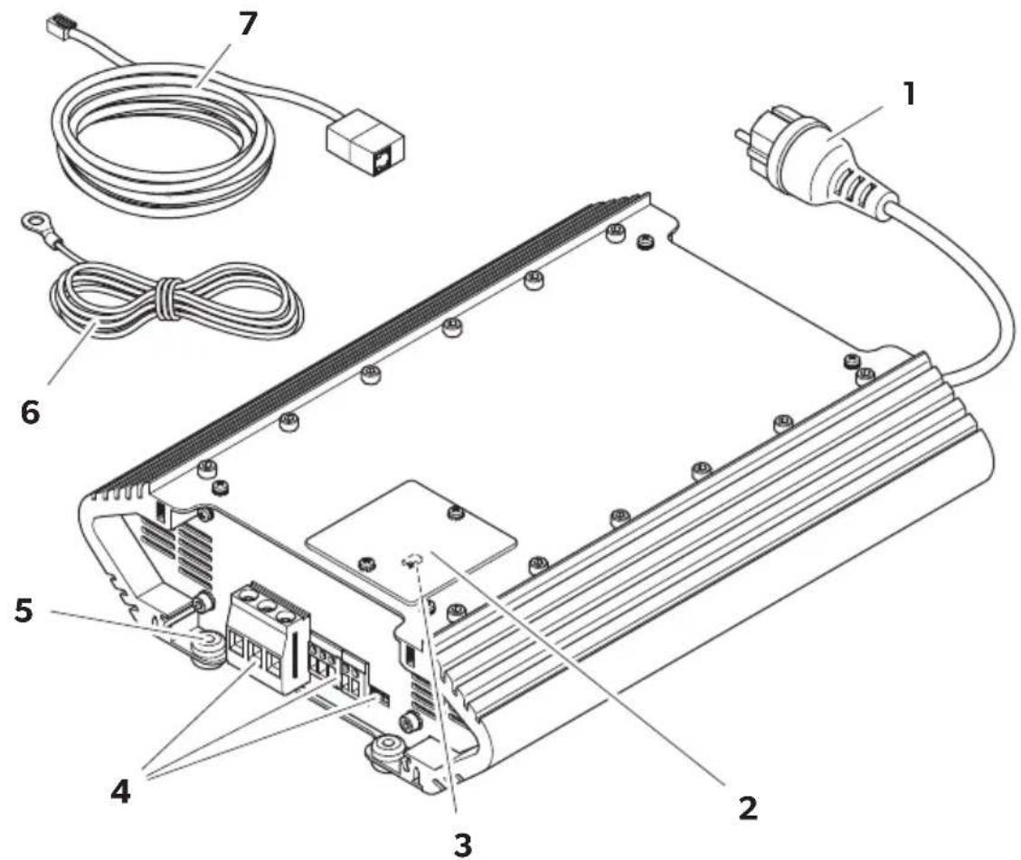
Description of the device
| No in fig. 1, page 3 Designation | ||||||||
| 1 | P | o | w | e | r | p | l | u |
| 2 | D | i | s | p | l | a | y | p |
| 3 | D | l | P | s | w | i | t | c |
| 4 Connections and controls | ||||||||
| 5 Rubber feet | ||||||||
| 6 Temperature sensor | ||||||||
| 7 Extension cable (5 m) with adapter for dis-play panel used for remote control | ||||||||
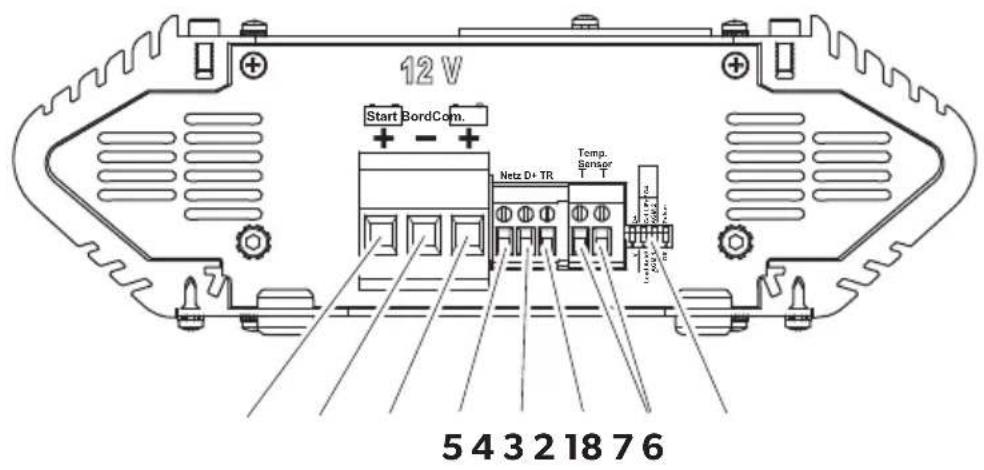
Connections and controls
| No in fig. 2, Designation Description page 3 |
| 1 DIP switches Setting of the charging program (see chapter “Setting the charging program” on page 21) and other functions. |
| 2 TT terminal 2 connections for temperature sensor |
| No in fig. 2, Designation Description page 3 |
| 3 TR terminal Output for controlling a cutoff relay (connection variants C, D) or a load relay (connection variant E) |
| 4 D+ terminal Input for D+ signal of the alternator or ignition lock signal (terminal 15) |
| 5 Netz Output for 12 V signal when connected to mains (max. 100 mA) |
| 6 BORD+ Connection to positive pole of 12 V house battery |
| 7 COM- Connection to negative pole of the house battery/chassis |
| 8 START+ Connection to positive pole of 12 V starting battery |
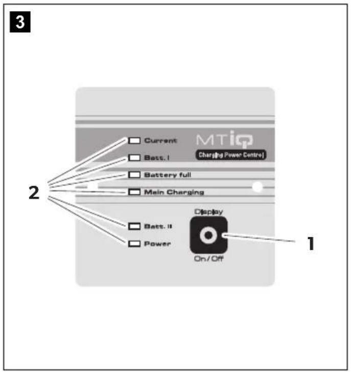
Display panel
| No in fig. 3, Designation page 4 | |
| 1 On/Off button | |
| 2 | I n d i c a t o |
Indicator LEDs on display panel
| LED Status Description | |
| Current (red) | On Charging current present; mains or booster charging mode; brightness indicates the intensity of the charging current |
| Off Charging current <0.2 A | |
| LED Status Description | |
| Batt. I (yellow) | On House battery is charged in mains or booster charging mode |
| Flashing • High temperature pro-tection • Only LiFePO4 batteries: Low temperature protec-tion (< -20 °C) | |
| Flashing slowly • Only LiFePO4 batteries: Low temperature protec-tion (< 0 °C) | |
| Off No charging | |
| Battery full (green) | On House battery fully charged (100 %); U2/U3 phase |
| Flashing Charging process in U1 phase (lead batteries: <75 %, LiFePO4 batteries: <90 %) | |
| Main Charging (yellow) | On Charging process in I/U1 phase |
| Flashing • Over voltage protection • Only LiFePO4 batteries: Temperature sensor is not connected | |
| Batt. II (yellow) r L | On Booster charging mode; starting battery charges the house battery |
| Off Booster charging not acti-vated | |
| Power (green) | On Voltage present; mains or booster charging mode |
| Flashing slowly • Safety shutdown(chapter "Troubleshooting" on page 24) • Internal device failure (overheating) | |
| Flashing in 20 s interval Pulsing operation mode | |
Battery charging function
A main charging cycle of the house battery is initiated in the following situations:
After a standstill of the alternator or mains failure
After falling below the reset voltage of 12.75V for lead batteries or 13.10V for LiFePO4 batteries for 30 s.

NOTE
In all charging phases (U1 phase to U3 phase), almost the entire possible charging current is available for the additional supply of DC loads without discharging the battery.
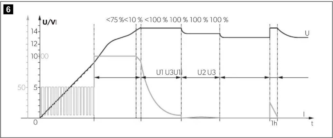
The charging characteristics for fully automated continuous operation without monitoring are referred to as modified IU0U characteristics (see charging curve in fig. 6, page 5).
1: Analysis phase
The battery is deeply discharged (>10%) . The battery charge is analyzed with increasing charging current.
2: I phase (Constant current phase)
At the beginning of the charging process, the empty battery is constantly charged with the maximum charging current (100%). The charging current decreases when the battery has reached a state of charge of 75% (90% for LiFePO4 batteries). Batteries with a voltage of 0 V are charged with reduced charging current until the battery voltage exceeds 9 V. The duration of the I phase depends on the state of the battery, the load from the DC loads and the state of charge. For safety reasons the I phase is terminated after a maximum of 15 h (in case of battery cell defects or similar).
3: U1 phase (Constant voltage phase)
The U1 phase starts when the battery is fully loaded. The charging current is reduced. During the U1 phase, the battery voltage is kept constant at a high level. The duration of the U1 phase depends on the battery type and the depth of discharge.
4: U2 phase (Trickle charging)
The U2 phase serves to maintain the battery capacity (100%). The U2 phase runs at lowered charging voltage and variable current. If DC loads are connected, they are powered by the device. Only if the power required exceeds the capacity of the device is this surplus power provided by the battery. The battery is then discharged until the device re-enters the I phase and charges the battery. The U2 phase is limited to between 24 and 48 h depending on the battery type.
5: U3 phase (Storage charging)
In long-term mains operation, the U3 phase prevents further discharge of the battery (e.g. during long breaks in use, seasonal operation or during winter storage), minimizes battery gassing and prevents plate corrosion.
6:Reconditioning
Twice a week, the charger switches back to the UI phase for a short time (max. 1 h) in order to revive the battery. This prevents any fatigue phenomena such as sulfation or electrolyte stratification.
Temperature sensor
With the temperature sensor connected, the battery control booster adjusts the charging voltage (for lead batteries) or the charging current (for LiFePO4 batteries) according to the measured temperature at the battery.

NOTE
- For lead batteries: Without temperature sensor connected, the charging voltage is referenced to 20^ .
- For LiFePO4 batteries: Without temperature sensor connected, the battery control booster does not work.
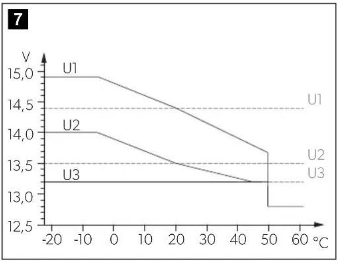
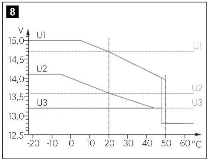
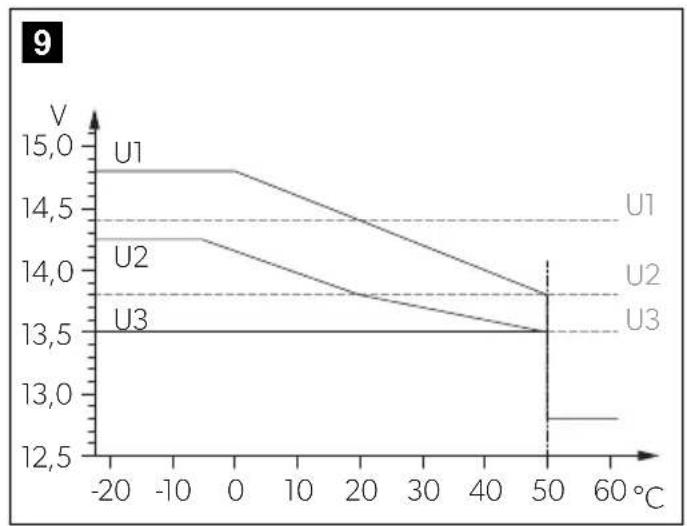
The charging characteristics are adjusted as follows:
- For lead acid batteries see fig. 7, page 5
- For AGM batteries see fig. 8, page 5
- For lead gel batteries see fig. 9, page 5
- For LiFePO4 batteries see fig. 10, page 5
| Charging curve without temperature sensor connected |
| Charging curve with temperature sensor connected |
Mounting the battery control booster
Installation location

NOTICE! Damage hazard
Before drilling any holes, ensure that no electrical cables or other parts of the vehicle can be damaged by drilling, sawing and filing.

NOTE
The battery control booster can be installed in any mounting position.
Observe the following instructions when selecting an installation location:
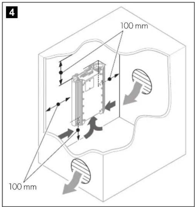
- Ensure that the mounting surface is solid and level.
- Observe the distance specifications (fig. 4, page 4).
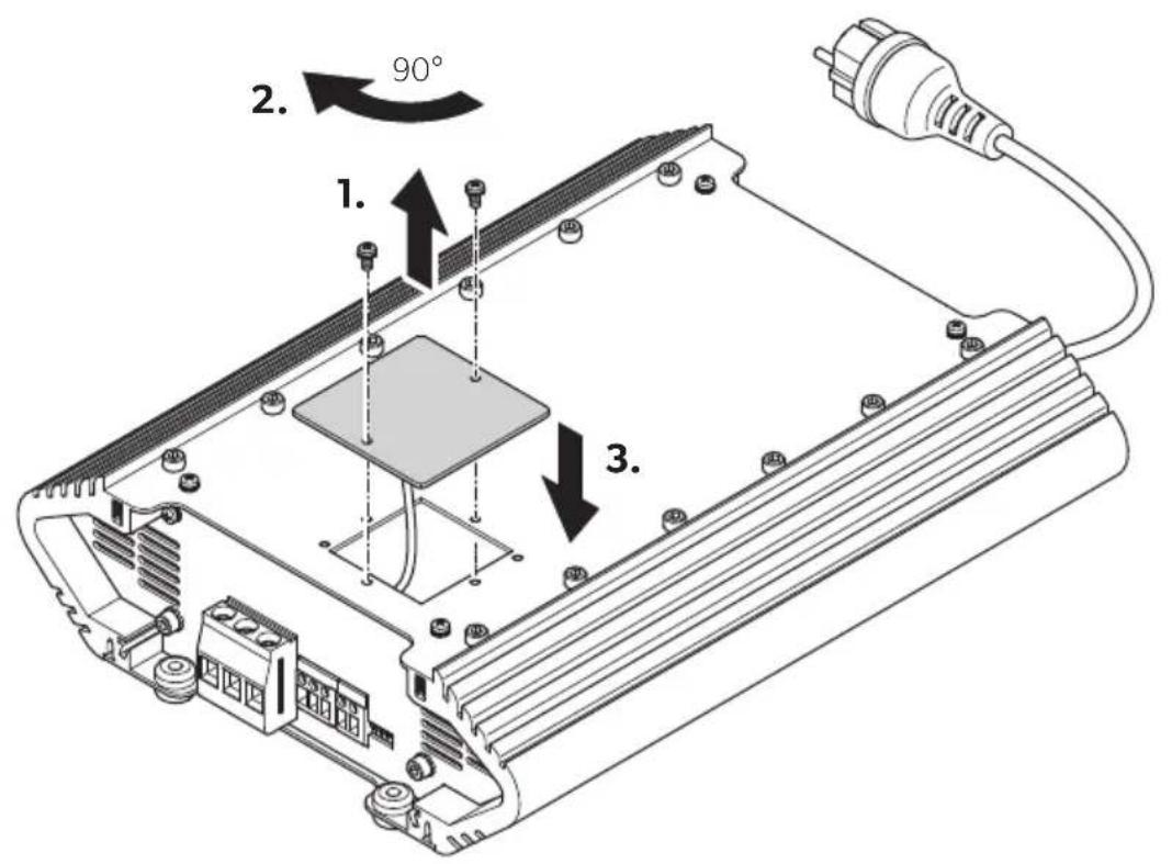
Using the display panel
The display panel can be mounted depending on the installation position of the battery control booster.
To rotate and reinsert the display panel in place proceed as shown in fig. 11, page 6.
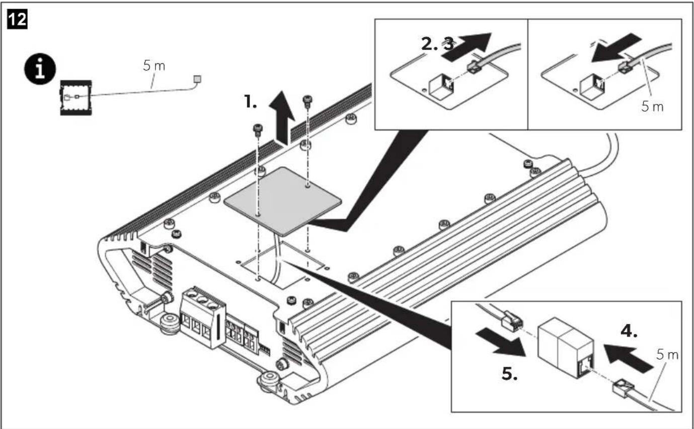
To use the display panel as a remote control pro ceed as shown in fig. 12, page 6.
Connecting the battery control booster
The electrical power supply must be connected by a qualified electrician who has demonstrated skill and knowledge related to the construction and operation of electrical equipment and installations and has received safety training to identify and avoid the hazards involved.

WARNING! Electrocution hazard
Observe the recommended cable cross-sections, cable lengths and fuse (see table on page 19).

CAUTION! Fire hazard
Place the fuses near the batteries to protect the cable from short circuits and possible burning.

NOTICE! Damage hazard
Do not reverse the polarity.

NOTE
- In the case of two or more batteries, parallel connection is permissible if the batteries are of the same type, capacity and age. Connect the batteries diagonally.
- For Dometic Böttner LiFePO4 batteries: To ensure measuring the internal temperature of the battery use the temperature sensor connector to connect the probe of the temperature sensor to the negative terminal of the house battery.
Observe the following instructions when connecting the battery control booster:
- Select the appropriate connection variant.
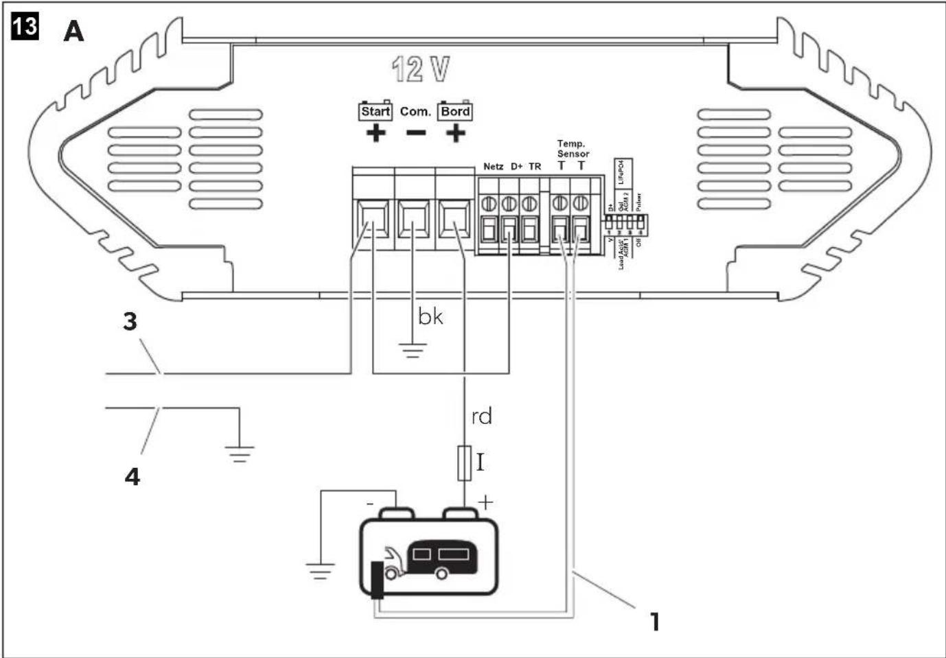
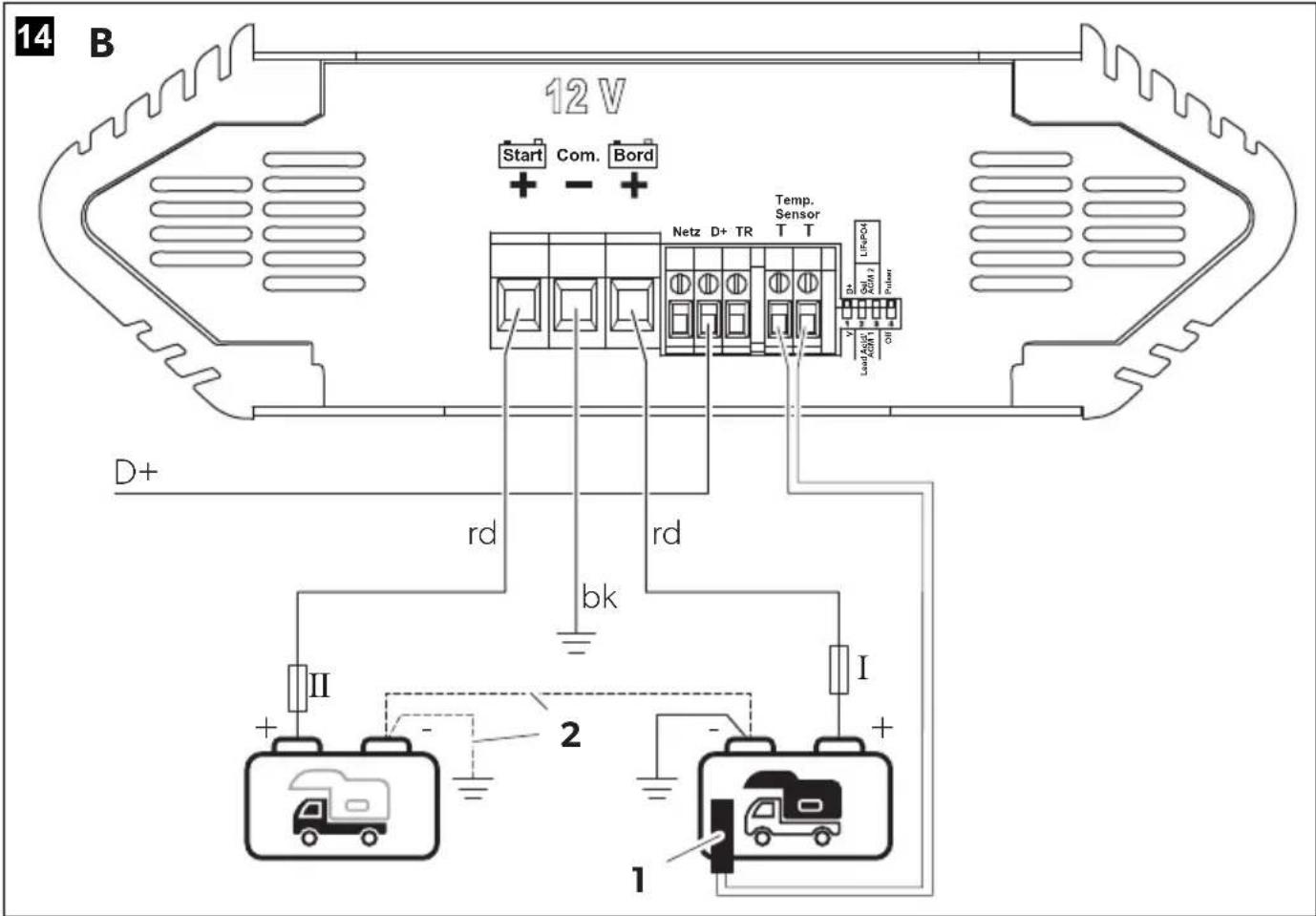
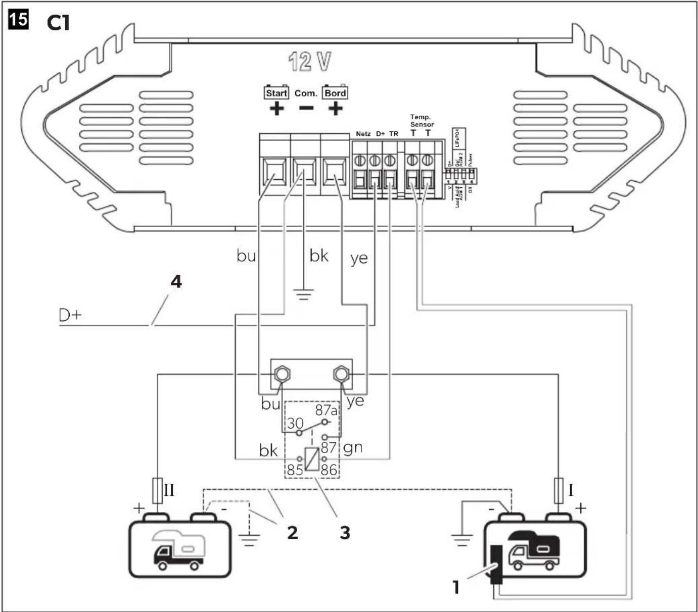
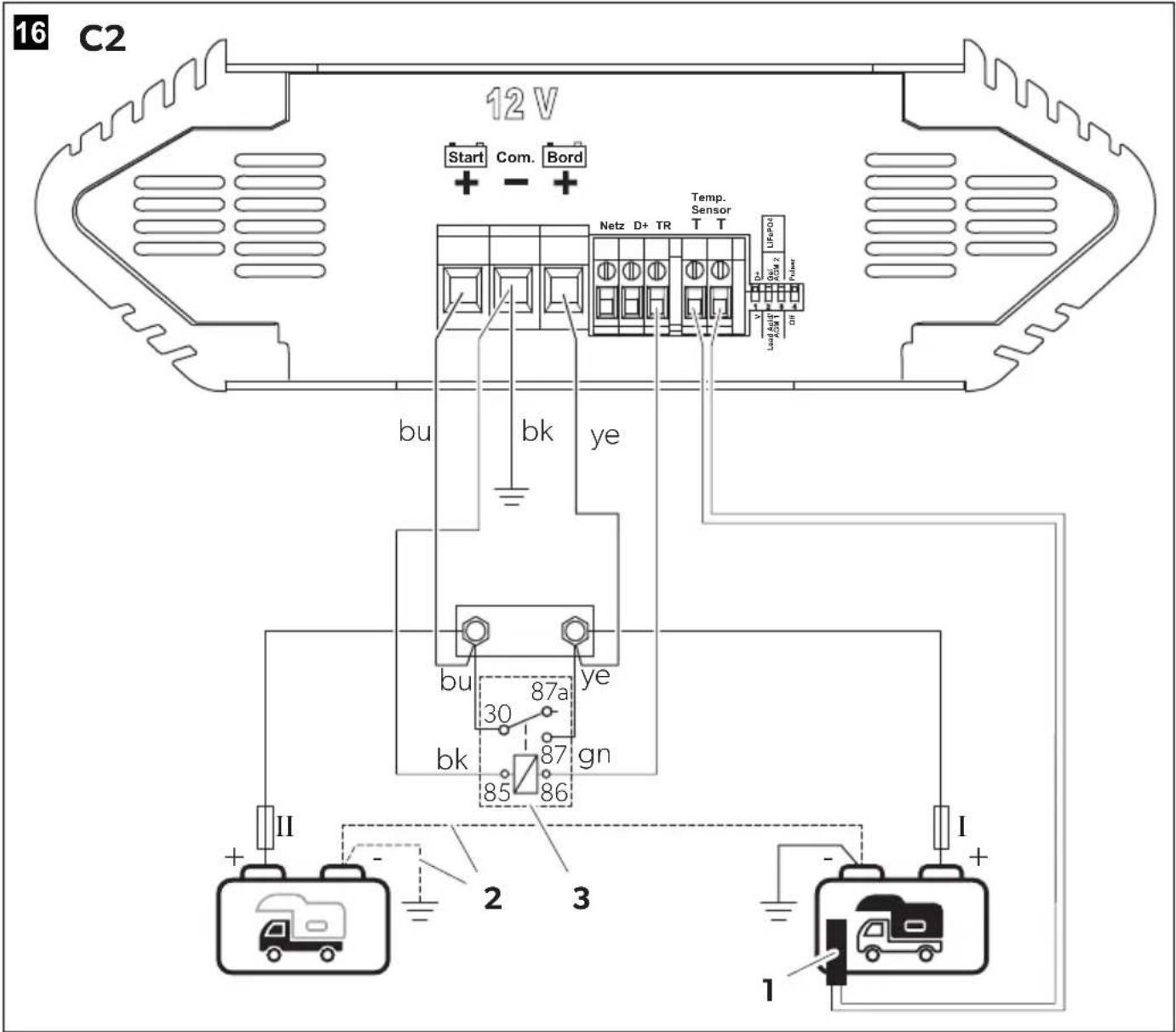
Legend for fig. 13, page 7 to fig. 16, page 10:

House battery

Starting battery
- Always connect the battery control booster before connecting the batteries.
-
Do not use ferrules. Strip the cable ends as follows:
-
Signal cable 12mm (0.5 - 1.5mm^2)
-
Charging cable 15 mm
-
Determine the cable cross-section:
| Cable cross-section | Cable length START+ to starting battery | Cable length COM- BORD+ to house battery |
2.5mm^2 >4m > 2m
4mm^2 >8m > 4m
- Protect the positive cable of the house battery with a fuse I (20 A).
- Protect the positive cable of the starting battery with a fuse II (30 A).
- Connect COM- to the negative terminal of the house battery or to ground (chassis).
- Connect BORD+ to the positive terminal of the house battery.
- Connect START+ to the positive terminal of the starting battery.
- Connect the negative terminal of the house battery to the negative terminal of the starting battery or to ground (chassis) (fig. 13 2, page 7 to fig. 16 2, page 10).
- Connect the probe of the temperature sensor to the negative terminal of the house battery (fig. 13 1, page 7 to fig. 16 1, page 10).
- Select the charging program suitable for the type of house battery used (see chapter "Setting the charging program" on page 21).
Connection variant A (fig. 13, page 7)
Connection variant for caravans, suitable for all 12 V towing vehicles according to previous and future standards, Euro 6+.

NOTICE! Damage hazard
Do not use a cutoff relay. To protect the trailer connector and the cables in the towing vehicle, the battery control booster limits the current consumption to 11 A in all charging phases.

NOTE
- A 13-pin trailer socket (according to ISO 11446) with a 12V charging cable (cable cross-section >2.5mm^2 ) is required for connection to the towing vehicle.
-
The battery control booster automatically switches off the voltage on pin 10 when the ignition is switched off.
-
The battery control booster is controlled via pin 10 by starting battery of the towing vehicle.
-
Slide the DIP switch (fig. 2 1, page 3) to the position "D+".
- Connect +START to pin 10 (charging connection trailer vehicle battery) of the 13-pin trailer socket (3).
- Connect the negative terminal of the starting battery of the towing vehicle to pin 13 of the 13-pin trailer socket (4).
- To connect the battery control booster proceed as shown in fig. 13, page 7.
Connection variant B (fig. 14, page 8)
Connection variant for small motor homes, suitable for all 12 V vehicles according to previous and future standards, Euro 6+.

NOTE
- This variant is unsuitable if connected consumers draw a higher current than 10 A, as the house battery can be discharged. In this case, use connection variant C1.
-
If the battery control booster is activated via terminal 15, the starting battery can be discharged when the ignition is switched on and the engine is not running. Use a D+ Active simulator if no D+ signal is available.
-
The battery control booster is controlled via the D+ signal of the alternator or the ignition lock signal (terminal 15).
-
Slide the DIP switch (fig. 2 1, page 3) to the position "D+".
- Connect the D+ terminal to the alternator (D+) or ignition lock signal (terminal 15).
- To connect the battery control booster proceed as shown in fig. 14, page 8.
Connection variant C1 (fig. 15, page 9)
Connection variant for small motor homes with a cutoff relay present, suitable for all 12 V vehicles according to previous and future standards, Euro 6+.

NOTE
- Use the load relay (NC 12 V, 80 A) with installation cable set if no cutoff relay is present.
-
If the battery control booster is activated via terminal 15, the starting battery can be discharged when the ignition is switched on and the engine is not running. Use a D+ Active simulator if no D+ signal is available.
-
The battery control booster is controlled via the D+ signal of the alternator or the ignition lock signal (terminal 15).
-
The cutoff relay is controlled via the TR terminal.
-
If the house battery is discharged or connected consumers draw a higher current than 10 A from the house battery the cutoff relay remains closed to enable charging currents higher than 10 A. After falling below this current or with increasing state of charge of the house battery, the cutoff relay is opened and the battery control booster takes over the charging process.
-
Slide the DIP switch (fig. 2 1, page 3) to the position "D+".
- Connect the D+ terminal to the alternator (D + ) or ignition lock signal (terminal 15) (4).
- Connect the cutoff relay (3) to the TR terminal.
- To connect the battery control booster proceed as shown in fig. 15, page 9.
Connection variant C2 (fig. 16, page 10)
Connection variant for small motor homes with a cutoff relay present, not suitable for vehicles according to newer standards Euro 6+.

NOTE
Use the load relay (NC 12 V, 80 A) with installation cable set if no cutoff relay is present.
- The battery control booster is controlled via the charging voltage at the starting battery.
- After starting the engine, the battery control booster is activated when the voltage at the starting battery increases. After switching off the engine, the battery control booster is deactivated when the voltage at the starting battery decreases.
- The cutoff relay is controlled via the TR terminal.
-
If the house battery is discharged or connected consumers draw a higher current than 10 A from the house battery the cutoff relay remains closed to enable charging currents higher than 10 A. After falling below this current or with increasing state of charge of the house battery, the cutoff relay is opened and the battery control booster takes over the charging process.
-
Slide the DIP switch (fig. 2 1, page 3) to the position "V".
-
Connect the cutoff relay (3) to the TR terminal.
-
To connect the battery control booster proceed as shown in fig. 16, page 10.
Operation

NOTICE! Damage hazard
Avoid frequent interruptions of the charging process. Fully charge the batteries regularly in mains operation.

NOTE
Use a small screwdriver to carefully move the DIP switches to the required position.
Setting the charging program

NOTICE! Damage hazard
Only use batteries that are suitable for the specified charging voltage.

NOTE
- Select the charging program suitable for the type of house battery used based on the manufacturer's specifications, the information in the table below and the technical data (see chapter "Technical data" on page 27).
- To protect sensitive consumers, the charging voltage is limited to 15V in all charging programs.
- The specified charging times apply to an average ambient temperature of 20^ .
▶ Slide the DIP switches (fig. 2 1, page 3) to the position shown in the table below to set the charging program for the respective type of house battery.
| DIP switch position (gray) | Desired charging program | U1 Full charge | U2 Full trickle charge | U3 Storage charging | |
| Lead Acid/ AGM 1 Off | D+ Gel LiFePO4 AGM 2 Pulser | Lead acid batteries/ AGM batteries (14.4 V) (fig. 7, page 5) | 14.4 V (1.5 – 6 h) | 13.5 V (24 h) | 13.2 V (regeneration 2 times per week: 14.4 V within 1 h) |
| Lead Acid/ AGM 1 Off | D+ Gel LiFePO4 AGM 2 Pulser | AGM batteries (14.7 V) (fig. 8, page 5) | 14.7 V (1.5 – 5 h) | 13.6 V (24 h) | 13.2 V (regeneration 2 times per week: 14.7 V within 1 h) |
| Lead Acid/ AGM 1 Off | D+ Gel LiFePO4 AGM 2 Pulser | Lead gel batteries (14.4 V) (fig. 9, page 5) | 14.4 V (4 – 12 h) | 13.8 V (48 h) | 13.5 V (regeneration 2 times per week: 14.4 V within 1 h) |
| Lead Acid/ AGM 1 Off | D+ Gel LiFePO4 AGM 2 Pulser | LiFePO4 batteries (14.4 V) (fig. 10, page 5) | 14.4 V (0.3 – 1 h) | 13.8 V (24 h) | 13.5 V (no regeneration) |
Selecting the function for the TR terminal

NOTE
- Select the function for TR terminal depending on the connection variant.
- To activate a change of the settings, disconnect the device temporarily from the power supply, the starting battery and the house battery.
▶ Slide the DIP switches (fig. 2 1, page 3) to the position shown in the table below to set the function for TR terminal.
DIP switch position (gray)
Connection variant
A, B
Note: Function selection for control via the D+ signal of the alternator or the ignition lock signal (terminal 15).
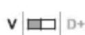
C1,C2
Note: Function selection for control via the charging voltage at the starting battery.
Switching threshold
Operation with control signal D+:
- Increase of charging power at START+ terminal > 9.8 V
- Reduction of charging power at START+ terminal < 9.5V
Operation without control signal D+:
- Increase of charging power at START+ terminal > 13.2 V
- Reduction of charging power at START+ terminal < 13.0 V
- Switch-off threshold: 13.0 V( 30 s)
Setting the pulsing operation

NOTE
- Only one pulser may be activated in a battery system at any one time. Set the DIP switch to the position "Off" to deactivate the pulsing operation if a pulser is already installed.
- The pulsing operation is automatically deactivated when the charging program for LiFePO4 batteries is set.
▶ Slide the DIP switches (fig. 2 1, page 3) to the position shown in the table below to activate or deactivate the pulsing operation.
The green "Power" LED flashes every 20 s.
Pulser is activated. The house battery is trained.
DIP switch position (gray)
Function
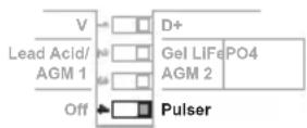
Pulser is automatically activated when neither mains nor booster operation is set:
Activation of pulser with voltage at BORD+ terminal at < 13.5V
- Deactivation of pulse with voltage at BORD+ terminal at < 11.00 V
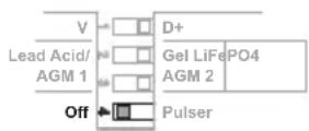
Pulser is deactivated.
Setting the night mode

NOTE
When using the night mode the system stays in this mode for 10 hours and then returns to normal operation.
In night mode the cooling fan is switched to the lowest speed for quiet operation. The display panel is darkened. All LEDs on the display panel except the "Current" LED are switched off.
To activate or deactivate the night mode press the On/Off button on the display panel once.
The "Current" LED lights up dimly red.
Limiting the charging current
To limit the charging current in booster mode, use the DIP switches on the back of the display panel (fig. 1 3, page 3).
| DIP switch position (gray) | Function |
| AB | Charging current limited to 10 A (factory setting) Note: Recommended for motor homes. |
| AB | Charging current limited to 8 A Note: Recommended for small caravan batteries. |
Interrupting the charging process
To interrupt the charging process in mains operation, pull out the power plug to disconnect the mains supply.
To interrupt the charging process in booster operation, disconnect the D+ terminal to interrupt the D+ signal of the alternator or the ignition lock signal.
Cleaning and maintenance

WARNING! Electrocution hazard
Unplug the device from the power supply before cleaning and maintenance.

NOTICE! Damage hazard
- Never clean the device under running water or in dish water.
- Do not use sharp or hard objects, abrasive cleaning agents or bleach during cleaning as these can damage the device.
Occasionally clean the device with a soft, damp cloth.
Regularly check live cables or lines for insulation faults, breaks or loose connections.
Ensure the device is operating properly by regularly checking the indicator LEDs on the display panel.
Troubleshooting
| Fault Possible cause Suggested remedy | ||
| The battery control booster does not work. The green "Power" LED does not light up. | Insulation faults, breaks or loose connections at the live cables. | Check live cables for insulation faults, breaks or loose connections. If you cannot find an error, contact an authorized service agent. |
| Short circuit has been generated. The device fuse must be replaced by an authorized service agent after it has been triggered by excess current. | ||
| The battery control booster does not work. The yellow "Main Charging" LED flashes. | Over voltage protection of the house battery. Battery voltages too high (>15.5 V). | Reduce the connected voltages (<12.75 V). Reset the device by removing the control signal at D+/terminal 15. Switch off the motor and disconnect the device from the mains. |
| Over voltage protection of the starting battery. Battery voltages too high (>16.5 V). | Reduce the connected voltages. The battery control booster restarts automatically when the voltage drops to the restart value (<16.5 V). | |
| Connection of defective charging systems. | Check and remove defective charging systems if necessary. | |
| Only LiFePO4 batteries: Temperature sensor is not connected. | Connect the temperature sensor. | |
| Unusually long charging time. The yellow "Batt. I" LED flashes. | High temperature protection: The battery control booster switches to reduced charging voltage (12.8 V) when the temperature of the battery exceeds the cutoff value (>50 °C). | Check that the air inlets and outlets are not covered or obstructed. Allow the battery to cool down. The battery control booster returns automatically to full charging voltage when the temperature drops to the restart value (<48 °C). |
| Low temperature protection (only for LiFePO4 batteries): The battery control booster switches to reduced charging voltage (12.8 V) when the temperature of the battery drops below the cutoff value (<20 °C). | Move the battery to a warmer location. The battery control booster returns automatically to full charging voltage when the temperature exceeds the restart value (>18 °C). | |
| Unusually long charging time. The yellow "Batt. I" LED flashes slowly. | Low temperature protection (only for LiFePO4 batteries): The battery control booster switches to reduced charging current when the temperature of the battery drops below the cutoff value (<0 °C). | Move the battery to a warmer location (>0 °C). The battery control booster restarts automatically when the temperature exceeds the restart value (>0 °C). |
| The battery control booster stops the charging process. The green "Power" LED flashes slowly. | Shutdown by safety timer. The I phase has lasted too long (>15 h). | Reset the device by removing the control signal at D+. Switch off the motor and disconnect the device from the mains. |
| Too many DC loads connected. | Reduce the connected DC loads. | |
| The battery is defective. | Replace the battery. | |
| Overheating of the battery control booster. | The battery control booster restarts automatically when the temperature drops. | |
| The battery is no longer taking a charge or is unable to hold a charge. | The battery is defective. | Replace the battery. |
| Full charging current is not reached. The green "Power" LED is lit. | The house battery is already charged. | Load with powerful consumers. |
| The battery terminals are not connected correctly. | Check the connections. Check the cable cross-sections and lengths (see table on page 19). Check the stripped cable ends. Check the voltages directly at the terminals. | |
| The battery is significantly sulfated. | Replace the battery. | |
| The DIP switch on the back of the display panel is set incorrectly. | Check the setting of the DIP switch on the back of the display panel (see chapter "Limiting the charging current" on page 23). | |
| Display panel only lights up poorly. | Night mode is activated. | Switch off the night mode (see chapter "Setting the night mode" on page 22). |
Disposal
Recycling packaging material

Place the packaging material in the appropriate recycling waste bins wherever possible.
Recycling products with non-replaceable batteries, rechargeable batteries or light sources
If the product contains any non-replaceable batteries, rechargeable batteries or light sources, you don't have to remove them before disposal.
If you wish to finally dispose of the product, ask your local recycling center or specialist dealer for details about how to do this in accordance with the applicable disposal regulations.
The product can be disposed free of charge.
Warranty
The statutory warranty period applies. If the product is defective, please contact your retailer or the manufacturer's branch in your country (see dometic.com/dealer).
For repair and warranty processing, please include the following documents when you send in the product:
- A copy of the receipt with purchasing date
- A reason for the claim or description of the fault Note that self-repair or nonprofessional repair can have safety consequences and might void the warranty.
Technical data
| Charging output house battery | |
| Nominal battery voltage 12 - 13.3 V--- | |
| Recommended battery capacity 40 - 150 Ah | |
| Maximum pre-charge current of a deeply discharged battery (0 - 9 V) | 5 A |
| Minimum battery voltage for start of charging | 0 V |
| Charging input/output starting battery | |
| Nominal battery voltage 12 V--- | |
| Recommended battery capacity 40 Ah | |
| Mains operation | |
| Nominal operating voltage (AC) 230 V~ / 45 - 65 Hz | |
| Voltage range • Full charging power 190 - 265 V~ • S h o r t - t i m e (5 s) 3 0 5 V ~ | |
| Sinusoidal current consumption, power factor correction (CosPhi = 1) | yes |
| Max. power consumption (AC) 165 W | |
| Max. current consumption (AC) 0.001 A | |
| Signal output “Netz”, indication light/max. | 12 V/ 0.1 A |
| Charging current, regulated (I phase) | 10 A |
| Charging/buffer/load current, regulated (U1, U2, U3 phase) | 0 - 10 A |
| Booster operation | |
| Max. power consumption (DC) | 125 W |
| Max. current consumption (DC) | 11.0 A |
| Minimum battery voltage for start of charging | 9.5 V |
| Charging/buffer/load current, regulated (U1, U2, U3 phase) | 0 - 10 A |
| Reduced charging/buffer/load current, regulated (U1, U2, U3 phase) | 0 - 8 A |
| Mains and booster operation | |
| Reverse current from battery | 0.003 A |
| Pulsing operation | |
| Double-peak current pulses, short-time | < 100 A |
| General technical data | |
| Protection class/ type | I/IP21 |
| Ambient temperature for operation | -20 °C to +45 °C |
| Ambient humidity | ≤ 95 %, non-con-densing |
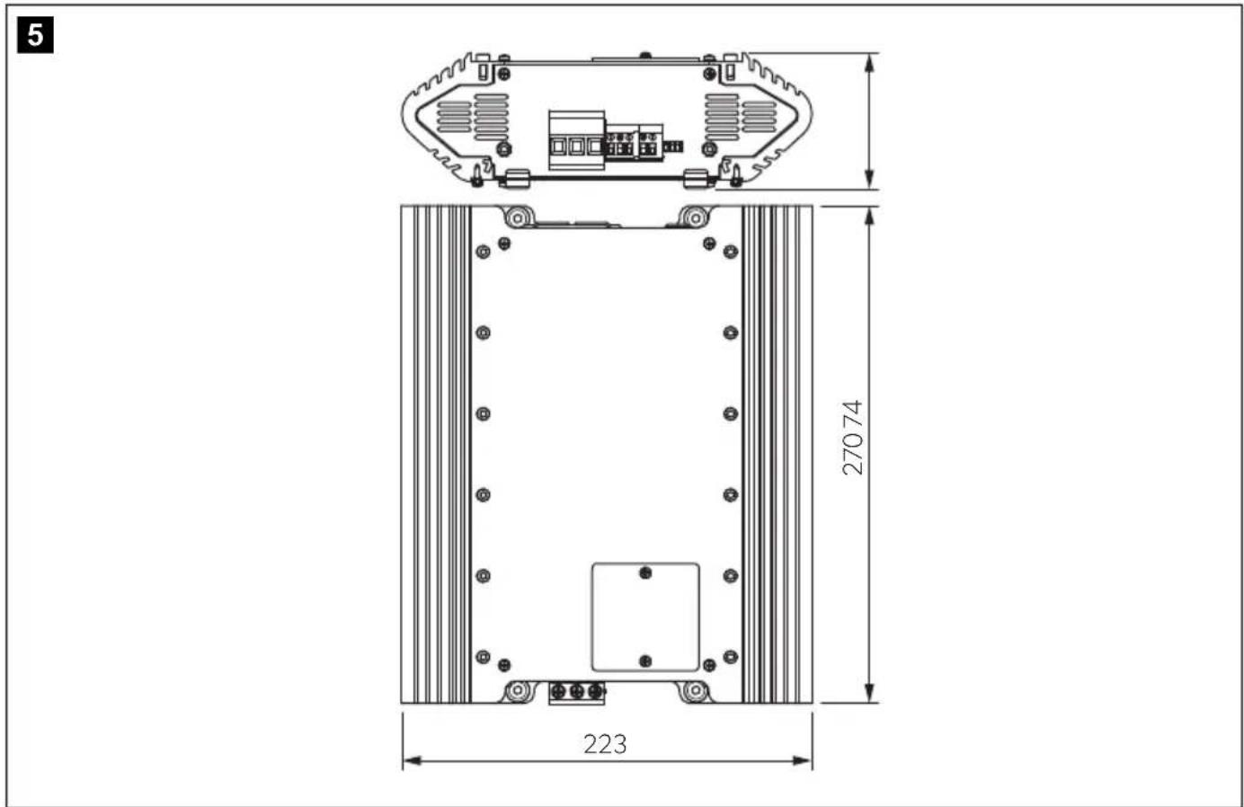
| Dimensions (W x D x H) | 270 x 223 x 74 mm (fig. 5, page 4) |
| Weight | 2.65 kg |
| Inspection/certification | CE UK CA |
DE
Description technique
5: Phase U3 (charge de stockage)
- Loodzuuuraccu's
- Gelaccu's
Vliesaccu's (AGM-accu's)
LFP-accu's
6: Herstel (reconditioning)
Sikker installing at apparatus

6: Reconditionering (Recondition)
FORSIGTIG! Brandfare
6: Rekonditionering (recondition)
Stille inn Iadeprogrammet

PASS PÄ! Fare for skader
Bruk kun batterier som er egnet for den spesifiserte ladespenningen.

MERK
dometic.com/sales-offices