
AXS-R7 - Flash Memory SONY - Free user manual and instructions
Find the device manual for free AXS-R7 SONY in PDF.

| Product type | Portable memory recorder |
| Brand | Sony |
| Model | AXS-R7 |
| Category | Flash Memory |
| Dimensions (W × H × D) | 106 × 135 × 93 mm |
| Weight | Approx. 1.2 kg (excluding accessories) |
| Power supply | 11 V to 17 V DC |
| Connectors | 144-pin expansion interface, DC IN XLR 4-pin male, DC OUT round 4-pin female, battery 5-pin |
| Compatible memory cards | AXS-A1TS24, AXS-A512S24, AXS-A256S24, AXS-A1TS48, AXS-A512S48 |
| Recording formats | F55RAW, X-OCN (XT, ST, LT) |
| Main functions | 4K 120 fps recording, 6K 90 fps (with license), image cache up to 30 s |
| Maintenance | Clean mount connector with cotton swab if dusty |
| Safety | Do not expose to rain/moisture; use only recommended Sony batteries and adapters; do not throw battery into fire |
| Spare parts and repairability | Battery (BP-FL75/BP-GL95B) and fan are consumables (replacement approx. every 5 years); AC adapter (AC-DN10A) and electrolytic capacitor have a lifespan of about 5 years |
| General information | Sony limited warranty; Class A CISPR 32 compliance; non-residential use |
Frequently Asked Questions - AXS-R7 SONY
User questions about AXS-R7 SONY
0 question about this device. Answer the ones you know or ask your own.
Ask a new question about this device
Download the instructions for your Flash Memory in PDF format for free! Find your manual AXS-R7 - SONY and take your electronic device back in hand. On this page are published all the documents necessary for the use of your device. AXS-R7 by SONY.
USER MANUAL AXS-R7 SONY
© 2016 Sony Corporation

安全のために
natural_image
Line drawing of an electronic device with a flame symbol above it (no text or labels)
すぐに接続機器の電源を切り、消火する。
警告表示の意味

ご注意
4-pin, Female
- External View -
| No. | 信号 | I/O | 仕様 | |||
| 1 | U | N | R | E | G-G | GND For UNREG |
| 2 | REC TALLY OUT Open Collector | |||||
| output(Max. 50 mA)Low: REC | ||||||
| No. 信号 | I/O | 仕様 |
| 3 REC TRIGGER IN Open or +5 V dc: Normal GND: Active (REC) | ||
| 4 UNREG +12 V OUT | OUT | +11 V to 17 V dc output |
ご注意
ご注意
natural_image
Exploded view diagram of an electronic device showing internal components and mounting holes (no text or labels)カムコーダーから取り外す
natural_image
Technical line drawing of an electrical contactor or relay device (no text or symbols visible)Before operating the unit, please read this manual thoroughly and retain it for future reference.
WARNING
To reduce the risk of fire or electric shock, do not expose this apparatus to rain or moisture.
To avoid electrical shock, do not open the cabinet. Refer servicing to qualified personnel only.
CAUTION
– Danger of explosion if battery is incorrectly replaced. Replace only with the same or equivalent type recommended by the manufacturer.
- When you dispose of the battery or the product, you must obey the law in the corresponding area or country. Do not dispose of the battery or the product in a fire or a hot oven, or mechanically crush or cut the battery. It may explode or cause a fire. Do not subject the battery to extremely low air pressure that may result in an explosion or the leakage of flammable liquid or gas.
- Do not place the battery in a high temperature place, such as under direct sunlight or near fire. It may ignite, explode, or cause a fire. Do not immerse or wet the battery in water or seawater. This may cause an electric shock.
Do not install the appliance in a confined space, such as book case or built-in cabinet.
WARNING
Batteries shall not be exposed to excessive heat such as sunshine, fire or the like.
IMPORTANT
The nameplate is located on the bottom.
This equipment is not suitable for use in locations where children are likely to be present.
For the customers in the U.S.A.
This equipment has been tested and found to comply with the limits for a Class A digital device, pursuant to part 15 of the FCC Rules. These limits are designed to provide reasonable protection against harmful interference when the equipment is operated in a commercial environment. This equipment generates, uses and can radiate radio frequency energy and, if not installed and used in accordance with the instruction manual, may cause harmful interference to radio communications. Operation of this equipment in a residential area is likely to cause harmful interference in which case the user will be required to correct the interference at his own expense.
You are cautioned that any changes or modifications not expressly approved in this manual could void your authority to operate this equipment.
This device complies with part 15 of the FCC Rules. Operation is subject to the following two conditions: (1) This device may not cause harmful interference, and (2) this device must accept any interference received, including interference that may cause undesired operation.
For the customers in Canada
CAN ICES-3 (A)/NMB-3(A)
For the customers in Europe
This product is intended for use in the following Electromagnetic Environments: E2 (commercial and light industrial), E3 (urban outdoors), E4 (controlled EMC environment, ex. TV studio).
For the customers in Europe, Australia and New Zealand
WARNING
This equipment is compliant with Class A of CISPR 32. In a residential environment this equipment may cause radio interference.
This apparatus shall not be used in the residential area.
경고
For the customers in the U.S.A. SONY LIMITED WARRANTY - Please visit http://www.sony.com/psa/warrantyfor important information and complete terms and conditions of Sony's limited warranty applicable to this product.
For the customers in Canada SONY LIMITED WARRANTY - Please visit http://www.sonybiz.ca/pro/lang/en/ca/article/resources-warranty for important information and complete terms and conditions of Sony's limited warranty applicable to this product.
For the customers in Europe Sony Professional Solutions Europe - Standard Warranty and Exceptions on Standard Warranty. Please visit https://pro.sony/support-services/primesupport/support-professional-solutions-europe-standard-product-warranty for important information and complete terms and conditions.
For the customers in Korea SONY LIMITED WARRANTY - Please visit http://bpeng.sony.co.kr/handler/BPAS-Start for important information and complete terms and conditions of Sony's limited warranty applicable to this product.
Usage Precautions
If the unit is suddenly taken from a cold to a warm location, or if ambient temperature suddenly rises, moisture may form on the outer surface of the unit and/or inside of the unit. This is known as condensation. If condensation occurs, turn off the unit and wait until the condensation clears before operating the unit. Operating the unit while condensation is present may damage the unit.
The fan and battery are consumable parts that will need periodic replacement.
When operating at room temperature, a normal replacement cycle will be about 5 years. However, this replacement cycle represents only a general guideline and does not imply that the life expectancy of these parts is guaranteed. For details on parts replacement, contact your dealer.
The life expectancy of the AC adapter and the electrolytic capacitor is about 5 years under normal operating temperatures and normal usage (8 hours per day; 25 days per month). If usage exceeds the above normal usage frequency, the life expectancy may be reduced correspondingly.
The battery terminal of this unit (the connector for battery packs and AC adaptors) is a consumable part. Power may not be supplied to the unit properly if the pins of the battery terminal are bent or deformed by shock or vibrations, or if they become corroded due to prolonged outdoor use. Periodic inspections are recommended to keep the unit working properly and to prolong its usable lifetime. Contact a Sony service or sales representative for more information about inspections.
Features Location and Function of Parts
The AXS-R7 is a portable memory recorder that uses AXS memory cards (A-series only) as the recording media. It features a toggle connector for connection to camcorders, such as the PMW-F5/F55 and MPC-3610 (VENICE/CineAltaV).
It supports recording and playback operations controlled from the connected camcorder.
Notes
- PMW-F5/F55 firmware version 8.0 or later is required for connection with the PMW-F5/F55.
- When used connected with an MPC-3610, the firmware version of the unit must match the MPC-3610 version. For details, refer to the operating instructions for the MPC-3610.
• High frame rate (HFR) function support
- 4K 120 FPS recording
Supports recording in 4K at 120 FPS when connected to a PMW-F55 or MPC-3610. 4K 5× slow recording is supported by recording at a system frequency of 23.98P.
- 6K 90 FPS recording
Supports recording in 6K at 90 FPS when connected to a MPC-3610 (VENICE/CineAltaV). A High Frame Rate license (CBKZ-3610H/3610HM/3610HW) is required for high frame rate shooting. For details, refer to the operating instructions for the MPC-3610 (VENICE/CineAltaV).
Note
Use AXS-A512S48 or AXS-A1TS48 memory cards when recording in 4K 120 FPS RAW SQ, 4K 120 FPS X-OCN ST, or 6K 90 FPS X-OCN. For details, refer to the operating instructions for the MPC-3610 (VENICE/CineAltaV).
• Recording in new X-OCN format
In addition to F55RAW recording mode, it also supports recording in the new, more efficient X-OCN recording mode.
• Picture cache function
Supports recording of video and audio data shot before recording is physically started by always caching several seconds (up to 30 seconds) of data in internal memory.
Note
Always disconnect the battery pack and DC IN connector DC supply cable before connecting or disconnecting another device to or from this unit.
Refer to the operating instructions for the connected camcorder when using this unit.
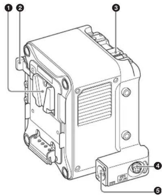
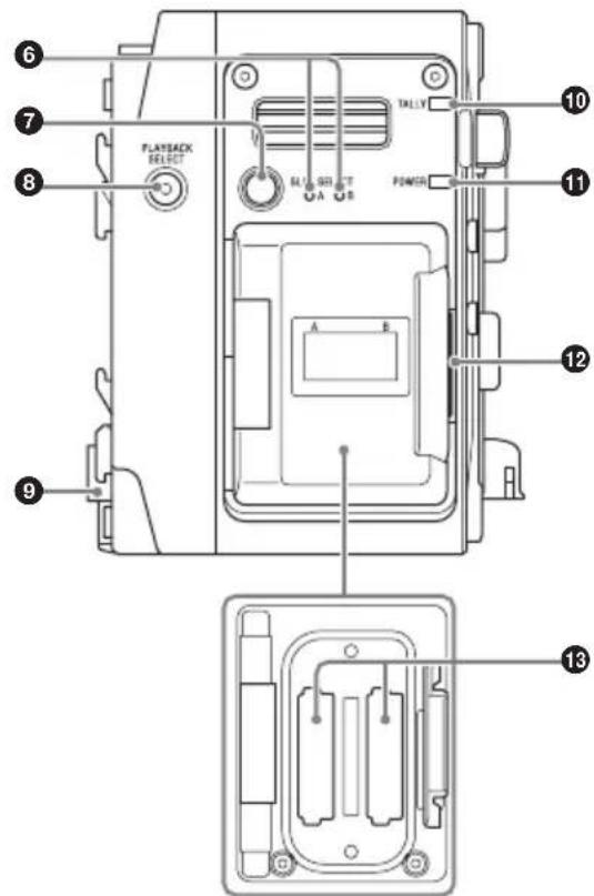
①Battery pack mount
Supplies power from a battery pack, or from an AC supply via an AC adaptor.
For safety, use only the Sony battery packs and AC adaptors listed below.
Battery pack: BP-FL75/BP-GL95B
AC adaptor: AC-DN10A
Notes
- Before installation, charge the battery pack using a battery charger.
- Charging the battery pack immediately after use when the temperature of the battery pack is high may not fully charge the battery pack.
②Battery release lever
Press to release the lock, allowing the battery pack to be removed.
③ Release lever
Press the release button to unlock and then lift the lever when attaching the unit to a camcorder and when removing the unit from a camcorder.
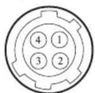
④DC OUT connector (4-pin)
Supplies 12 V DC power to peripheral devices, such as a monitor or LED light. A REC Tally signal output and REC Trigger signal input can also be connected via the DC OUT connector.
4-pin, female
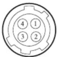
- External View -
No. Signal I/O Specification
| 1 UNREG GND – GND for UNREG | |
| 2 REC TALLY OUT Open-collector | |
| output(Max. 50 mA) | |
| Low: REC | |
| 3 REC TRIGGER IN Open or +5 V DC: | |
| NormalGND: Active(REC) | |
| 4 UNREG +12 V OUT | OUT +11 V to 17 V DC output |
Note
Connect only devices with current consumption rating of 1.8 A or lower to the DC OUT connector. If an overcurrent condition is detected, output stops. Check the connection with peripheral devices and then turn on the power supply again.
⑤DC IN connector
Supplies DC power to the unit using the optional DC power supply cable.
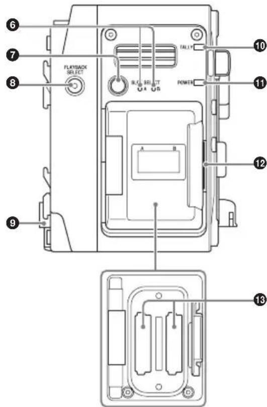
⑥Access lamps A/B
Indicates the state of card slots A and B.
Red: Accessing the inserted AXS memory card
Green: Standby state (mounted AXS memory card is ready for playback/recording)
Off: Valid memory card is not inserted
⑦SLOT SELECT button
When memory cards are mounted in both card slots A and B, press this button to select the memory card to use.
⑧ PLAYBACK SELECT button/indicator
The indicator is lit when playback is enabled. When not lit, press the PLAYBACK SELECT button to enable playback.
Playback is controlled from the connected camcorder.
⑨Camera mount connector
Connects to a camcorder to deliver both signal and power.
Note
A data transfer error may occur if there is any dust or other matter adhering to the camera mount connector. If the connector is dirty, clean the connector using a cotton swab.
⑩ TALLY lamp
Lit when recording is in progress.
It flashes when an error or warning condition occurs. The main causes are indicated below. For other causes, refer to the operation manual for the connected camcorder.
Flashing (1 time/sec): Remaining media warning (about 5 minutes)
Flashing (4 times/sec): No remaining media or an error occurred
⑪POWER indicator
Lit when power is supplied from the camcorder.
⑫Memory slot cover open button
Press to open the cover when inserting/removing an AXS memory card.
⑬AXS memory card slots A/B
Insertion slots for AXS memory cards. Insert an AXS memory card all the way into the slot with the AXS logo mark facing the battery.
The following AXS memory cards can be used in the unit.
• AXS-A1TS24 (1 TB/2.4 Gbps)
• AXS-A512S24 (512 GB/2.4 Gbps)
• AXS-A256S24 (256 GB/2.4 Gbps)
• AXS-A1TS48 (1 TB/4.8 Gbps)
• AXS-A512S48 (512 GB/4.8 Gbps)
Using with a Camcorder
This section describes connection with the PMW-F5/F55.
When connecting the unit to the MPC-3610, refer to the operating instructions for the MPC-3610.
Attaching to a Camcorder
Note
Turn off the camcorder before attaching/removing the unit.
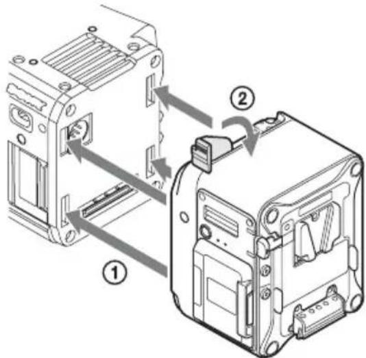
1 Press the release button on the unit (①) to pop-up the release lever, then raise the release lever till it points up (②).
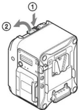
2 Insert the tabs on the unit into the grooves on the rear surface of the camcorder (①), and lower the release lever (②).
Notes
- Attach the unit after raising the release lever.
- Check that the four tabs are securely engaged before lowering the release lever. If not engaged, the unit may not be attached properly or may damage the camcorder or unit.
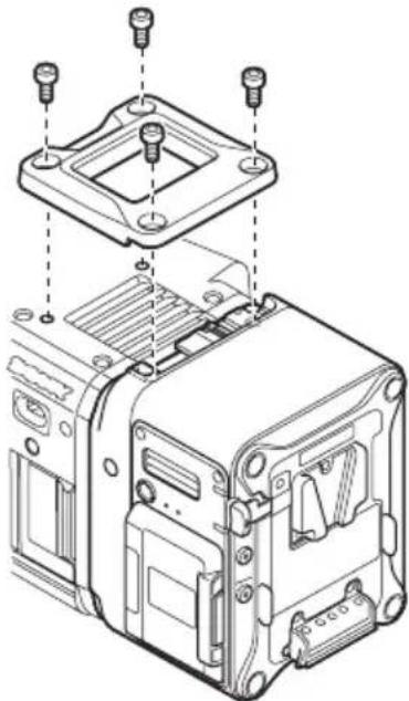
3 Screw the supplied top plate onto the unit and camcorder (hex key wrench size 3/16").
natural_image
Exploded view diagram of an electronic device showing internal components and mounting points (no text or labels)Removing from a Camcorder
1 Remove the top plate from the unit and camcorder.
2 Press the release button and raise the release lever, then slide the unit upward and pull it out towards you.
Note
Always support the unit with your hand when removing.
Inserting an AXS Memory Card
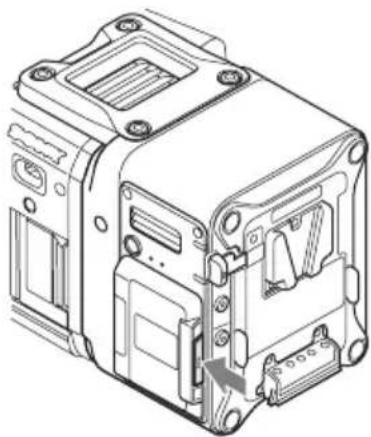
1 Press the memory slot cover open button on the right side to open the cover.
natural_image
Technical line drawing of an electronic device casing with mounting holes and internal components (no text or symbols)2 Insert an AXS memory card into the card slot with the label facing the direction shown in the diagram.
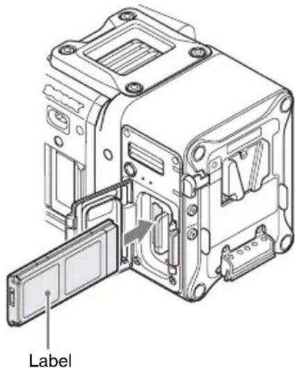
3 Close the cover.
Note
Push the cover in until the memory slot cover open button is securely locked.
Removing an AXS Memory Card
Open the memory slot cover on the unit, and extract the AXS memory card by hand.
Note
Data integrity is not guaranteed if the power is turned off or a memory card is removed while it is being accessed. All data recorded on the card may be destroyed. Always check that the memory card ACCESS lamp is lit green or off when you turn off the power or remove a memory card.
Specifications
General
Power requirement
11 V to 17 V DC
Power consumption
Approx. 24 W (4K 59.94P)
Operating temperature
0^ to 40^ (32°F to 104°F)
Operating humidity
20% to 90%
Storage temperature
-20^ to +60^ (-4^ to +140^)
Dimensions
106 × 135 × 93 ~mm
(4^1/4×5^3/8×3^3/_4in.)
(width / height / depth)
(Refer to dimensions diagram at the back of this document.)
Mass
Approx. 1.2 kg (2 lb. 10 oz.) (excluding supplied accessories)
Input/output connectors
Extension interface connector
144-pin (1), supplies power
DC IN connector
XLR 4-pin, male (1)
DC OUT connector
Round type 4-pin, female (1)
Battery connector
5-pin (1)
Recording format
Video
F55RAW format
X-OCN format
Audio
Linear PCM (48 kHz/24-bit), 4-channel
Recording/playback time
6K 1.85:1 (using AXS-A512S48) (MPC-3610
only)
X-OCN XT: Approx. 26 minutes (23.98P)
X-OCN ST: Approx. 37 minutes (23.98P)
X-OCN LT: Approx. 64 minutes (23.98P)
6K 2.39:1 (using AXS-A512S48) (MPC-3610 only)
X-OCN XT: Approx. 33 minutes (23.98P)
X-OCN ST: Approx. 48 minutes (23.98P)
X-OCN LT: Approx. 82 minutes (23.98P)
6K 3:2 (using AXS-A512S48) (MPC-3610 only)
X-OCN XT: Approx. 20 minutes (23.98P)
X-OCN ST: Approx. 30 minutes (23.98P)
X-OCN LT: Approx. 52 minutes (23.98P)
6K 17:9 (using AXS-A512S48) (MPC-3610 only)
X-OCN XT: Approx. 26 minutes (23.98P)
X-OCN ST: Approx. 38 minutes (23.98P)
X-OCN LT: Approx. 65 minutes (23.98P)
4K 2.39:1 (using AXS-A512S48) (MPC-3610 only)
X-OCN XT: Approx. 72 minutes (23.98P)
X-OCN ST: Approx. 105 minutes (23.98P)
X-OCN LT: Approx. 177 minutes (23.98P)
4K 4:3 (using AXS-A512S48) (MPC-3610 only)
X-OCN XT: Approx. 41 minutes (23.98P)
X-OCN ST: Approx. 60 minutes (23.98P)
X-OCN LT: Approx. 102 minutes (23.98P)
4K 6:5 (using AXS-A512S48) (MPC-3610 only)
X-OCN XT: Approx. 36 minutes (23.98P)
X-OCN ST: Approx. 53 minutes (23.98P)
X-OCN LT: Approx. 90 minutes (23.98P)
4K 17:9 (using AXS-A512S48)
RAW SQ: Approx. 60 minutes (23.98P)/
Approx. 24 minutes (59.94P)
X-OCN XT: Approx. 57 minutes (23.98P)
X-OCN ST: Approx. 84 minutes (23.98P)/
Approx. 33 minutes (59.94P)
X-OCN LT: Approx. 142 minutes (23.98P)/
Approx. 56 minutes (59.94P)
2K (using AXS-A512S48)
RAW SQ: Approx. 240 minutes (23.98P)/
Approx. 96 minutes (59.94P)
X-OCN ST: Approx. 333 minutes (23.98P)/
Approx. 135 minutes (59.94P)
X-OCN LT: Approx. 506 minutes (23.98P)/
Approx. 207 minutes (59.94P)
Note
The recording/playback time is equivalent to the duration of a single clip recording that fills the media. The recording/playback time may become shorter,
depending on the number of recorded clips.
Supplied Accessories
Top cover (4-598-229-xx) (1)
Top cover retaining screws (4-562-604-xx) (4)
Operating Instructions (1)
Warranty (1)
Design and specifications are subject to change without notice.
Notes
• Always make a test recording, and verify that it was recorded successfully. SONY WILL NOT BE LIABLE FOR DAMAGES OF ANY KIND INCLUDING, BUT NOT LIMITED TO, COMPENSATION OR REIMBURSEMENT ON ACCOUNT OF FAILURE OF THIS UNIT OR ITS RECORDING MEDIA, EXTERNAL STORAGE SYSTEMS OR ANY OTHER MEDIA OR STORAGE SYSTEMS TO RECORD CONTENT OF ANY TYPE.
• Always verify that the unit is operating properly before use. SONY WILL NOT BE LIABLE FOR DAMAGES OF ANY KIND INCLUDING, BUT NOT LIMITED TO, COMPENSATION OR REIMBURSEMENT ON ACCOUNT OF THE LOSS OF PRESENT OR PROSPECTIVE PROFITS DUE TO FAILURE OF THIS UNIT, EITHER DURING THE WARRANTY PERIOD OR AFTER EXPIRATION OF THE WARRANTY, OR FOR ANY OTHER REASON WHATSOEVER.
- SONY WILL NOT BE LIABLE FOR CLAIMS OF ANY KIND MADE BY USERS OF THIS UNIT OR MADE BY THIRD PARTIES.
- SONY WILL NOT BE LIABLE FOR THE LOSS, REPAIR, OR REPRODUCTION OF ANY DATA RECORDED ON THE INTERNAL STORAGE SYSTEM, RECORDING MEDIA, EXTERNAL STORAGE SYSTEMS OR ANY OTHER MEDIA OR STORAGE SYSTEMS.
- SONY WILL NOT BE LIABLE FOR THE TERMINATION OR DISCONTINUATION OF ANY SERVICES RELATED TO THIS UNIT THAT MAY RESULT DUE TO CIRCUMSTANCES OF ANY KIND.
Français
Remarque
Remarques
natural_image
Exploded view diagram of an electronic device showing internal components and mounting holes (no text or labels)natural_image
Technical line drawing of an electrical enclosure or device housing with mounting holes and internal components (no text or symbols)Environ 24 W (4K 59.94P)
Environ 24 minutes (59.94P)
X-OCN XT : Environ 57 minutes (23.98P)
X-OCN ST : Environ 84 minutes (23.98P)/
Environ 33 minutes (59.94P)
X-OCN LT : Environ 142 minutes (23.98P)/
Environ 56 minutes (59.94P)

Hinweis
Hinweise
natural_image
Exploded view diagram of an electronic device showing internal components and mounting holes (no text or labels)natural_image
Technical line drawing of an electronic device housing with internal components and mounting holes (no text or symbols)ca. 24 W (4K 59.94P)
Betriebstemperatur
0 °C bis 40 °C
Linear PCM (48 kHz/24 Bit), 4-Kanal
Obere Abdeckung (4-598-229-xx) (1)

Nota
Note
natural_image
Exploded view diagram of an electronic device showing internal components and mounting holes (no text or labels)natural_image
Technical line drawing of an electrical contactor device (no text or symbols visible)Circa 24 W (4K 59.94P)

Nota
Notas
natural_image
Exploded view diagram of an electronic device showing internal components and mounting holes (no text or labels)natural_image
Technical line drawing of an electronic device casing with internal components and mounting holes (no text or symbols)natural_image
Technical line drawing of an electronic device internal structure with a door open and a cable inserted (no text or symbols)Etiqueta
3 Cierre la tapa.
Nota

Примечание
Примечания
natural_image
Exploded view diagram of an electronic device showing internal components and mounting holes (no text or labels)natural_image
Technical line drawing of an electrical contactor device (no text or symbols visible)natural_image
Technical line drawing of an electronic device internal structure with a door and connector (no text or symbols)Ярлык
Закройте крышку.
Примечание
