BKM-250TG - Video adapter SONY - Free user manual and instructions
Find the device manual for free BKM-250TG SONY in PDF.

| Product type | 3G/HD/SD-SDI Input Adapter for Sony Professional Monitors |
| Brand | Sony |
| Model | BKM-250TG |
| Dimensions (L × H × D) | 100 × 20 × 162 mm |
| Weight | Approx. 270 g |
| Power Supply | +3.3 V and +5 V supplied by the main unit, power consumption approx. 4 W |
| Input Connectors | 2 × BNC (3G/HD/SD-SDI serial digital input) |
| Output Connector | 1 × BNC (monitor output for control) |
| Supported Signal Formats | 3G-SDI (1080/50P, 1080/60P), HD-SDI, SD-SDI |
| Main Functions | Decoder for serial digital signals, timecode display (SMPTE-12M-2), audio level meter display (CH1 to CH16, level -60 dB to -0.01 dB) |
| Operating Temperature | 0 °C to 35 °C |
| Operating Humidity | 0 % to 90 % (non-condensing) |
| Storage Temperature | -20 °C to +60 °C |
| Compliance | CE (EN55103-1/2), Class A (Canada NMB-003), suitable for E1, E2, E3, E4 environments |
| Medical Safety | Compliant with IEC60601-1-1, compatible with medical equipment under conditions (isolation transformer) |
| Included Accessories | Instruction manual (1) |
| Maintenance and Cleaning | Clean with a soft dry cloth. Do not use solvents. Disconnect before cleaning. |
| Repairability | Spare parts not specified. Contact an authorized Sony service center for any repairs. |
Frequently Asked Questions - BKM-250TG SONY
User questions about BKM-250TG SONY
0 question about this device. Answer the ones you know or ask your own.
Ask a new question about this device
Download the instructions for your Video adapter in PDF format for free! Find your manual BKM-250TG - SONY and take your electronic device back in hand. On this page are published all the documents necessary for the use of your device. BKM-250TG by SONY.
USER MANUAL BKM-250TG SONY
3G/HD/SD-SDI Input Adaptor
取扱説明書 JP
Operating Instructions ____ GB
Mode d'emploi FR
Bedienungsanleitung DE
Istruzioni per l'uso IT
Manual de instrucciones ____ ES
使用说明书 ____ CS
使用說明書 CT
취급 설명서 KR
Before operating the unit, please read this manual thoroughly and retain it for future reference.
Important safeguards/notices for use in the medical environments
- All the equipments connected to this unit shall be certified according to Standard IEC60601-1, IEC60950-1, IEC60065 or other IEC/ISO Standards applicable to the equipments.
- Furthermore all configurations shall comply with the system standard IEC60601-1-1. Everybody who connects additional equipment to the signal input part or signal output part configures a medical system, and is therefore, responsible that the system complies with the requirements of the system standard IEC60601-1-1. If in doubt, consult the qualified service personnel.
- The leakage current could increase when connected to other equipment.
- For this particular equipment, all accessory equipment connected as noted above, must be connected to mains via an additional isolation transformer conforming with the construction requirements of IEC60601-1 and providing at least Basic Insulation.
- This equipment generates, uses, and can radiate radio frequency energy. If it is not installed and used in accordance with the instruction manual, it may cause interference to other equipment. If this unit causes interference (which can be determined by unplugging the power cord from the unit), try these measures: Relocate the unit with respect to the susceptible equipment. Plug this unit and the susceptible equipment into different branch circuit.
Consult your dealer. (According to standard EN60601-1-2 and CISPR11, Class B, Group 1)
WARNING
For the customers in the U.S.A.
This equipment has been tested and found to comply with the limits for a Class A digital device, pursuant to Part 15 of the FCC Rules. These limits are designed to provide reasonable protection against harmful interference when the equipment is operated in a commercial environment. This equipment generates, uses, and can radiate radio frequency energy and, if not installed and used in accordance with the instruction manual, may cause harmful interference to radio communications. Operation of this equipment in a residential area is likely to cause harmful interference in which case the user will be required to correct the interference at his own expense.
You are cautioned that any changes or modifications not expressly approved in this manual could void your authority to operate this equipment.
All interface cables used to connect peripherals must be shielded in order to comply with the limits for a digital device pursuant to Subpart B of Part 15 of FCC Rules.
This device complies with Part 15 of the FCC Rules. Operation is subject to the following two conditions: (1) this device may not cause harmful interference, and (2) this device must accept any interference received, including interference that may cause undesired operation.
For the customers in Canada
This Class A digital apparatus complies with Canadian ICES-003.
For the customers in Europe
This product with the CE marking complies with the EMC Directive issued by the Commission of the European Community. Compliance with this directive implies conformity to the following European standards:
• EN55103-1 : Electromagnetic Interference(Emission)
• EN55103-2 : Electromagnetic Susceptibility(Immunity)
This product is intended for use in the following Electromagnetic Environments: E1 (residential), E2 (commercial and light industrial), E3 (urban outdoors), E4 (controlled EMC environment, ex. TV studio).
For the customers in Europe
The manufacturer of this product is Sony Corporation, 1-7-1 Konan, Minato-ku, Tokyo, Japan.
The Authorized Representative for EMC and product safety is Sony Deutschland GmbH, Hedelfinger Strasse 61, 70327 Stuttgart, Germany.
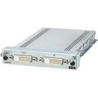
Overview
The BKM-250TG 3G/HD/SD-SDI Input Adaptor is a video signal input adaptor for
Sony professional monitors.
When installed in an input option slot on the main unit, it provides video input and output connectors for the main unit and a decoder for 3G/HD/SD serial digital component signals.
Note
There are some monitors that are not compatible with this unit.
To check if the monitor is compatible with this unit, refer to the operating instructions for the monitor.
Function
Decoder for serial digital component signals
The BKM-250TG supports 3G-SDI that transmits 1080/50P or 1080/60P signals using a single BNC cable, and is equipped with a built-in decoder for 3G/HD/SD serial digital component signal.
Serial digital input and output signal connector
The BKM-250TG is equipped with two input connectors and monitor output connectors that correspond to each input signal for serial digital signals.
Time code display
The BKM-250TG can decode the time code that is superimposed on the serial digital signals, and display those time code over the video signals.
Audio level meter display
The BKM-250TG can display the audio level of the embedded audio over the video signals.
Using the Input and Output Connectors
For information about installing the BKM-250TG in an input option slot on the main unit, refer to the operating instructions for the monitor.
Configuration of input/output connectors and signals that may be input
The configuration of the input and output connectors, and the signals that may be input are shown below.
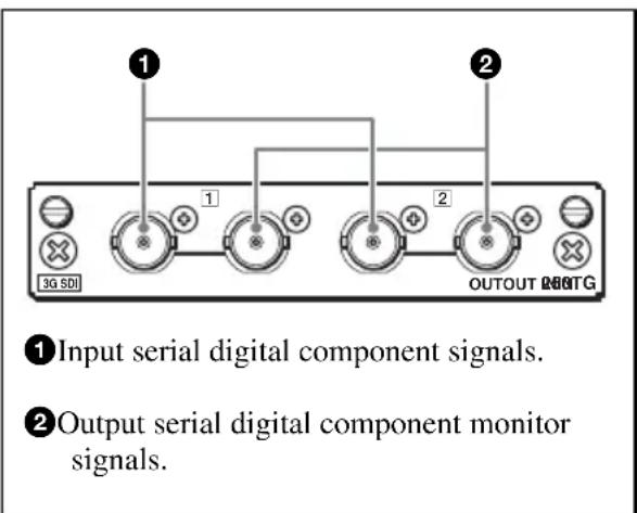
Input of serial digital component signals
You can input serial digital signals to connectors ① and output signals displayed on the screen of the main unit or the monitor from connector ②.
You need not attach the 75Ω termination to connector 2.
Notes
- The OUT connector (monitor out) outputs signal only when the power of the main unit is ON. The monitor out signal is not output when the monitor is in standby mode.
- The signal from the OUT connector does not comply with ON-LINE output signal specifications.
Specifications
General
Voltage +3.3 V, +5 V (supplied from the main unit)
Power consumption
Approx. 4 W
Operating conditions
Temperature
0^ to 35^ (32°F to 95°F)
Optimum temperature
20^ to 30^ (68°F to 86°F)
Humidity 0% to 90% (no condensation)
Pressure 700 hPa to 1060 hPa
Storage and transport conditions
Temperature -20^ to +60^ (-4^ to
+140 °F)
Humidity 0% to 90%
Pressure 700 hPa to 1060 hPa
Maximum external dimensions (w/h/d)
100 × 20 × 162 ~mm
(4×^13 / 16× 6^1 / 2 inches)
Mass Approx. 270 g (9.5 oz)
Input/Output connectors
Digital input
BNC (2), with monitor output connector
Available signal format
Refer to the operating instructions of the monitor.
Signal characteristics
Digital component signals
Sampling frequency
3G-SDI: Y/Cb/Cr (4:2:2)
148.5 MHz/74.25 MHz/
74.25 MHz
Y/Cb/Cr (4:4:4)
148.5 MHz/148.5 MHz/
148.5 MHz
G/B/R 148.5 MHz/
148.5 MHz/148.5 MHz
HD-SDI: Y/Cb/Cr
74.25 MHz/37.125 MHz/
37.125 MHz
SD-SDI: Y/Cb/Cr
13.5MHz/6.75MHz/
6.75 MHz
Quantization
3G-SDI: 10 bits/sample, 12 bits/sample
HD-SDI: 10 bits/sample
SD-SDI: 10 bits/sample
OUT connector (monitor out)
Output signal amplitude:
800 mVp-p ±10%
Output impedance: 75Ω
unbalanced
Transmission distance
3G-SDI: 70 m (approx. 230 ft)
max. (When using 5C-FB
coaxial cables (Fujikura. Inc.)
or equivalent.)
HD-SDI: 100 m (approx. 328 ft)
max. (When using 5C-FB
coaxial cables (Fujikura. Inc.)
or equivalent.)
SD-SDI: 200 m (approx. 656 ft)
max. (When using 5C-2V
coaxial cables (Fujikura. Inc.)
or equivalent.)
Time code display
Available standard
SMPTE-12M-2
Time code type
VITC, LTC
Notes
• Not available for analog signal.
- Depending on the SCAN setting of the monitor, a part of the displayed picture including the time code may be invisible.
Audio level meter display
Channel
CH1 to CH8 or CH9 to CH16
Level
-60 dB to -0.01 dB
Color
-0.01 dB to 0 dB: Red
-1.25 dB to -0.01 dB: Orange
-20 dB to -1.25 dB: Yellow
-60 dB to -20 dB: Green
Note
Depending on the SCAN setting of the monitor, a part of the displayed picture including the audio level meter may be invisible.
Supplied accessories
Operating Instructions (1)
Design and specifications are subject to change without notice.
Note
Always verify that the unit is operating properly before use. SONY WILL NOT BE LIABLE FOR DAMAGES OF ANY KIND INCLUDING, BUT NOT LIMITED TO, COMPENSATION OR REIMBURSEMENT ON ACCOUNT OF THE LOSS OF PRESENT OR PROSPECTIVE PROFITS DUE TO FAILURE OF THIS UNIT, EITHER DURING THE WARRANTY PERIOD OR AFTER EXPIRATION OF THE WARRANTY, OR FOR ANY OTHER REASON WHATSOEVER.
Français
74.25 MHz/37.125 MHz/
37.125 MHz
SD-SDI: Y/Cb/Cr
13.5 MHz/6.75 MHz/
6.75 MHz
74.25 MHz/37.125 MHz/
37.125 MHz
SD-SDI: Y/Cb/Cr
13.5 MHz/6.75 MHz/
6.75 MHz
74.25 MHz/37.125 MHz/
37.125 MHz
SD-SDI: Y/Cb/Cr
13.5 MHz/6.75 MHz/
6.75 MHz
For Customer in China
Printed on recycled paper.
Sony Corporation
Printed in Japan
4144436020