WRR-855S - TV SONY - Free user manual and instructions
Find the device manual for free WRR-855S SONY in PDF.

User questions about WRR-855S SONY
0 question about this device. Answer the ones you know or ask your own.
Ask a new question about this device
Download the instructions for your TV in PDF format for free! Find your manual WRR-855S - SONY and take your electronic device back in hand. On this page are published all the documents necessary for the use of your device. WRR-855S by SONY.
USER MANUAL WRR-855S SONY
UHF Synthesized Tuner Unit
Operating Instructions ____ GB
©2008 Sony Corporation

3452095130
English
Owner's Record
The model and serial numbers are located at the rear of the unit. Record the serial number in the space provided below. Refer to these numbers whenever you call upon your Sony dealer regarding this product.
Model No. WRR-855S
Serial No.
For the customers in the U.S.A.
If you have any questions about this product, you may call; Sony Customer Information Service Center 1-800-222-7669 or http://www.sony.com/
Declaration of Conformity
Trade Name: SONY
Model No.: WRR-855S
Responsible Party: Sony Electronics Inc.
Address: 16530 Via Esprillo, San
Diego, CA 92127 U.S.A.
Telephone No.: 858-942-2230
This device complies with part 15 of the FCC Rules. Operation is subject to the following two conditions: (1) this device may not cause harmful interference, and (2) this device must accept any interference received, including interference that may cause undesired operation.
You are cautioned that any changes or modifications not expressly approved in this manual could void your authority to operate this equipment.
All interface cables used to connect peripherals must be shielded in order to comply with the limits for a digital device pursuant to Subpart B of Part 15 of FCC Rules.
For the customers in Canada
Use of Sony wireless devices is regulated by the Industry Canada as described in their Radio Standard Specification RSS-123.
A licence is normally required. The local district office of Industry Canada should therefore be contacted. When the operation of the device is within the broadcast band, the license is issued on no-interference, no-protection basis with respect to broadcast signals.
Operation is subject to the following two conditions: (1) this device may not cause interference, and (2) this device must accept any interference, including interference that may cause undesired operation of the device.
The term “IC:” before the radio certification number only signifies that Industry Canada technical specifications were met.
CE
For the customers in Europe
Hereby, Sony Corporation, declares that this WRR-855S is in compliance with the essential requirements and other relevant provisions of the Directive 1999/5/EC.
For details, please access the following URL :http://www.compliance.sony.de/
Parts Identification 7
WRR-855S 7
BTA-801 Portable Tuner Mount Adapter (not supplied) 8
Preparations 9
Attaching the Antennas 9
Attaching to a Sony Camcorder 9
Using a Portable Tuner Mount Adapter ....10
Settings 11
Setting the Reception Channel ....11
Selecting and Cancelling the T (Tone Squelch) OFF Mode ....13
Display Messages 15
Important Notes on Operation 16
On Usage and Storage 16
On Cleaning ....16
Specifications ....17
Features
The WRR-855S UHF Synthesized Tuner Unit in use with an optional Portable Tuner Mount Adapter, such as the BTA-801, provides a highly reliable portable diversity tuner for the Sony UHF wireless microphone system, which uses the frequency bands allocated for UHF TV broadcasting.
This tuner unit enables the application of multiple channels over unused television channels through the use of the built-in Sony original channel plan.
Preprogrammed wireless channel plans for simultaneous multi channel operation
The WRR-855S has many preprogrammed channel groups, meaning combination of wireless channels to permit simultaneous operation of multiple channels without intermodulation.
For the channel plans available on your unit, see "Wireless Microphone System Frequency List" supplied with this manual.
Versatile display
A variety of information is obtained at a glance on the upper panel, such as the reception channel with the LCD panel. The three LEDs are also provided on the upper panel to respectively indicate RF input level (indicated in green and red), AF level, and the battery alarm for the transmitter.
Space diversity reception system
The WRR-855S provides stable signal reception with only a minute amount of dropout.
Compact and lightweight
Innovative, high-density mounting technology has enabled the creation of this compact, lightweight tuner unit. Using the optional BTA-801 Portable Tuner Mount Adapter in combination, the WRR-855S can be easily attached to the Sony Camcorder.
Weatherproof structure
By properly mounting the WRR-855S to the optional BTA-801 Portable Tuner Mount Adapter and attaching the two supplied antennas, a weatherproof structure is obtained.
Selectable squelch
The squelch can be easily turned on or off with the panel switch.
Tone-squelch circuit for noise elimination
The unit uses a built-in squelch circuit to selectively receive the desired RF carrier accompanied by the tone signal from the transmitter.
Compander system
A commander (compressor/expander) system enables stabilized wireless transmission over a wide dynamic range.
Parts Identification
text_image
WRR-855S 1 2 3 4 5 6 7 8 9 10 11 12 BTA-801 (not supplied) 13 14 15WRR-855S
①POWER switch
Turns the power on or off.
②CH (channel selection) button
Press and hold down for at least three seconds to go to the channel group selection mode and the channel group number flashes on the display.
For details, see "Settings" on page 11.
③GP (channel group selection) button
Press and hold down for at least three seconds to go to the channel selection mode and the channel number flashes on the display.
For details, see "Settings" on page 11.
④LCD panel
When you turn on the power, the version number of your WRR-855S ("U62," for example) appears, then the tuner unit goes to normal display mode.
text_image
A B C RF AF GF/CH 0 1.620 1 The group/channel indications (©) for U62 model are shown.ⒶRF (radio frequency) input level indications
The number of dots shows the RF input level as follows.
Four dots on: more than 30 dB
Three dots on: between 25 dBμ and 30 dBμ
Two dots on: between 20 dBμ and 25 dBμ
One dot on: between 10 dBμ and 20 dBμ
No dot: less than 10 dB
©AF (audio frequency) indication
Appears whenever the input audio signal is stronger than the reference level.
©GP (group)/CH (channel) indication
Shows the group and channel of the reception channel.
For details, see "Settings" on page 11.
⑤+ (+ selection) / - (- selection) buttons
Press these buttons to set the group and channel of the reception channel.
For details, see "Settings" on page 11.
⑥ Antenna a/b connectors
Connect the two supplied antennas to these connectors.
⑦SQUELCH switch
In ordinary use, set the switch to ON, and the noise and signal interference will be eliminated when the tuner unit is in signal reception stand-by mode. Set to OFF to search outside noise or a radio wave which may disrupt the signal transmission.
Notes
- If you turn off the SQUELCH switch when the tuner unit is in stand-by status for signal reception or when the RF input level is low, noise may be heard or the connected device or speakers may be damaged. Be sure to operate this switch only after turning down the input volume on the connected device.
- If you use the tuner unit at the temperature of 0^ (32°F) or below, dropouts in signal reception may occur. If this happens, turn off the SQUELCH switch.
⑧Mounting screws (4)
Used to secure the WRR-855S to the BTA-801.
For details, see “Using a Portable Tuner Mount Adapter” on page 10.
⑨TX BATT (transmitter battery) indicator
Shows the battery condition of the transmitter (e.g., Sony WRT-series transmitter or wireless microphone which is provided with battery alarm function). The indicator starts flashing about one hour before the transmitter batteries are drained.
⑩AF (audio frequency) indicator
Lights up whenever the audio signal output is stronger than the reference level.
11RF (radio frequency) input level indicator
Indicates the strength of the RF input signal.
On in green: RF input is more than 25 dB .
On in red: RF input is between 10 dB and 25 dB .
Off: RF input is less than 10 dB .
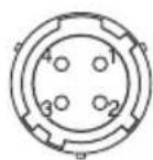
⑫ Accessory connector
For the signal and power connections with the BTA-801.
Pin assignment
1: AF GND
2: AF OUTPUT
4: DC +7 V
5: GND
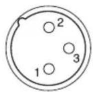
BTA-801 Portable Tuner Mount Adapter (not supplied)
13DC 12V IN (power input) connector Connect to an external power supply (DC 10 to 17 V) of a Camcorder using the DC power cable supplied with the BTA-801.
Pin assignment
1: GND
2: NC
3: NC
4: +12 V
Note
Be sure to check the operating voltage and polarity when connecting to a power source.
14 Camcorder attachment knob
Used to fix the unit to a Camcorder.
For details on attaching to a Camcorder, see "Attaching to a Sony Camcorder" on page 9.
15 OUTPUT connector (XLR 3-pin, male)
Supplies audio signals. You can connect this to the microphone input connector of a Camcorder, mixer, tape recorder or other similar equipment.
Pin assignment
1: GND
2: HOT
3: COLD
Note
When connecting to an audio mixer which has a phantom powering capability for microphones, it is recommended to use the mixer with the phantom power off.
Preparations
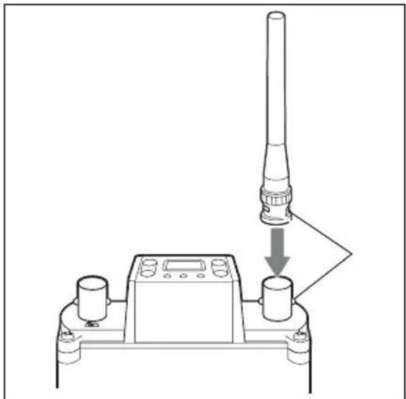
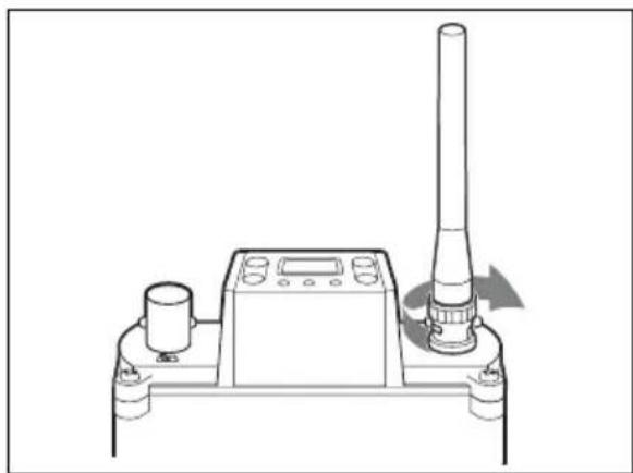
Attaching the Antennas
Attach the supplied antennas to the antenna a/b connectors.
1 Align the protruding part of the connector with the antenna slot.
natural_image
Diagram of a device with a vertical cylindrical component being processed, showing a downward arrow and control panel (no text or symbols)2 Turn the antenna to lock.
natural_image
Technical line drawing of a mechanical device with a vertical cylindrical component and control panel (no text or symbols)Attaching to a Sony Camcorder
On the HDW/DVW/MSW/PDW-series Camcorder, a slot for mounting the wireless
tuner unit is equipped. The WRR-855S can be attached to the Camcorder using that slot.
For details on how to attach the WRR-855S to the Camcorder, refer to the Operation Manual supplied with the Camcorder.
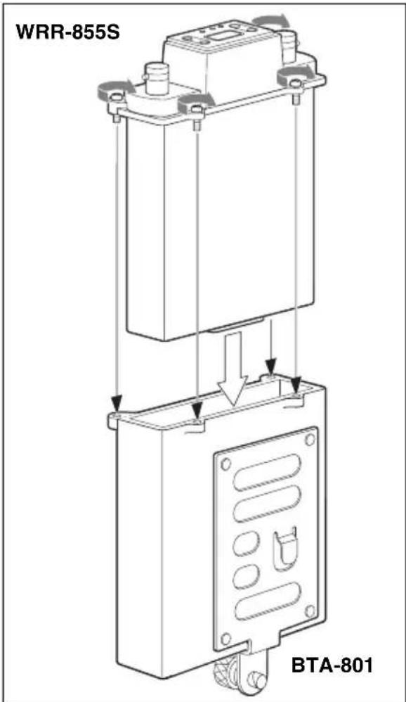
Using a Portable Tuner Mount Adapter
This section shows you how to mount the WRR-855S to the BTA-801 Portable Tuner Mount Adapter (not supplied) for example. By properly mounting the WRR-855S to the BTA-801 and attaching the two supplied antennas, a weatherproof structure is obtained.
To mount the tuner unit to the portable tuner mount adapter
Note
Before mounting, be sure to clean the abutting surfaces of the WRR-855S and the BTA-801.
1 After observing the direction, insert the WRR-855S in the BTA-801.
2 Push the WRR-855S down until the accessory connector clicks into place.
3 Run in the four mounting screws little by little in turn to gradually secure the tuner unit and the adapter together, then tighten them.
text_image
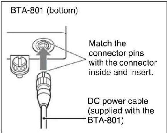
WRR-855S BTA-801To connect the power cable
Connect the DC 12 V IN connector of the BTA-801 to the DC OUT connector of the Camcorder using the DC power cable supplied with the BTA-801.
text_image
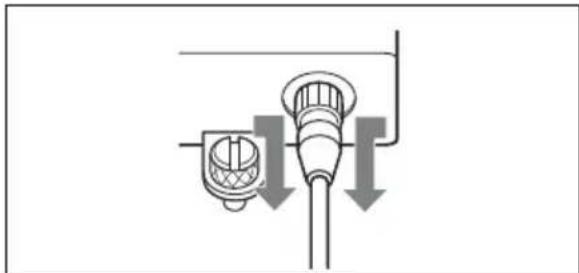
BTA-801 (bottom) Match the connector pins with the connector inside and insert. DC power cable (supplied with the BTA-801)To remove the power cable
Pull the metal part of the connector in the direction of the arrows and remove.
natural_image
Pure diagram of a pipe or tube with directional arrows indicating flow or movement, no text or symbols present.Settings
Setting the Reception Channel
Note
Take the following precautions to prevent interference and noise.
- Do not simultaneously use two or more UHF synthesized wireless microphones/transmitters that are set to the same channel.
- To operate two or more UHF synthesized wireless microphones/transmitters using the same channel of the same group, ensure that the wireless microphones/transmitters are at least 100 m (330 feet) ^1) apart as far as they are installed within sight of each other.
- When using two or more of WRR-855S simultaneously, always set the tuner units to different channels within the same channel group (other than channel group 00).
- When using two or more of WRR-855S, do not directly put one unit upon the other.
- The antennas of the tuner unit and the transmitter should be at least 3 meters apart from each other.
- If there is a TV broadcasting station nearby, to avoid possible interference from its broadcast, do not use that station's channel.
- The number of wireless channels actually usable in a multi-channel system may be smaller than the normal capacity of that system if there is interference from TV broadcasting or other RF signals.
1) The distance depends on the operating environment and conditions.
Refer to the supplied leaflet “Sony Wireless Microphone System Frequency List” for details on the selectable channel groups and channels.
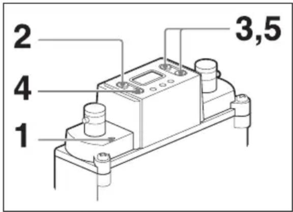
text_image
1 2 3,5 41 Turn the POWER switch to ON.
The version number of your tuner unit (“U62,” for example) appears in the LCD panel, then the display changes to the status shown before the tuner unit was previously turned off.
Note
Before operating the POWER switch, be sure to turn down the input volume on the connected device. If not, noise may be produced.
2 Press and hold down the GP button for more than three seconds.
The tuner unit goes to the channel group selection mode and the channel group indication flashes.
text_image
0.16201The group/channel indications for U62 model are shown.
3 Press the + or - button to select the channel group.
Pressing the + button cyclically changes the indication in the order shown in the tables in the supplied leaflet “Sony Wireless Microphone System Frequency List.”
Pressing the – button cycles the indication in the opposite direction. Hold down the + or – button to continuously change the indication.
When no buttons have been pressed for five seconds, the channel group selection mode is automatically cancelled and the lowest frequency channel in the group selected at that time is displayed.
For the group 00, however, the channel previously set in group 00 appears.
4 When the desired channel group number appears, press the CH button.
The selected channel group is entered and the tuner unit goes to the channel selection mode and the channel number indication flashes.
text_image
0 1:5:20 1The group/channel indications for U62 model are shown.
5 Press the + or - button to select the channel number.
The indication cyclically changes in the order shown in the tables in the supplied leaflet “Sony Wireless Microphone System Frequency List.”
text_image
Example: When the channel group 00 is selected for U62 model 08.620 1 ←→ 08.6247 08.6547 ↑ 08.650 1 ↓ 08.6447 ←→ 08.630 1 08.6347 ↑ 08.640 16 When the desired channel number is displayed, leave the tuner unit for about five seconds until the selected channel number indication stops flashing and the selection is stored in memory.
Interference-check function
Before operating a wireless microphone or transmitter, you can check for possible interference by using the interference-check function of this tuner unit.
To check the interference, simultaneously press the + and - buttons in the channel selection mode (while the channel number indication flashes). The channels of the selected group are automatically switched one by one in sequence (this operation is called “scanning”).
Notes
- When the SQUELCH switch is set to ON and the tuner unit is not in the T OFF mode (see page 13), scanning stops and the channel at that time is selected if a tone signal (32.768 kHz) is detected in the signal received during scanning.
However, scanning will not stop if a interfering signal having no tone signal is received. In this case, check for the interference by observing the RF input level indicator or the RF (radio frequency) input level indications in the display.
- Scanning is automatically cancelled when all the channels of the selected group are scanned twice. To cancel scanning in progress, press any of the operation buttons.
- If an extremely strong signal is received, scanning may stop at a point other than the actual channel.
Selecting and Cancelling the T (Tone Squelch) OFF Mode
The WRR-855S has the following three squelch functions, which work in combination.
(1) Squelch by RF input level
As sufficient S/N for the audio output may not be obtained if no RF signal is received or the RF input level is low, the audio output is turned off when the RF input level falls below the selected level.
(2) Tone squelch
The audio output is obtained as long as the tuner unit receives an RF signal which includes a specified tone signal.
(3) Noise squelch
The audio output is turned off to eliminate noise which may be heard when there is such excessive interference RF signal that the tone squelch does not work.
Only the tone squelch function described in (2) above can be canceled by selecting the T (tone squelch) OFF mode. Apply this mode
when you use a transmitter with no specified tone signal.
Selecting the T OFF Mode
1 Turn the power switch to ON while pressing and holding the GP and - buttons.
2 Release the buttons after the version number of your tuner unit (“U62,” for example) appears.
“T OFF” is momentarily displayed and the tuner unit goes to the T OFF mode. The T OFF mode is maintained even when the power is turned OFF.
Cancelling the T OFF Mode
1 Turn the power switch to ON while pressing and holding the GP and + buttons.
2 Release the buttons after the version number of your tuner unit ("U62," for example) appears.
“T ON” is momentarily displayed and the T OFF mode is cancelled.
Display Messages
In addition to the normal indications, the following messages may appear in the LCD panel.
| Message Meaning Measures | ||
| Err 01 An error | occurred in backup memory data. | Contact your Sony dealer. |
| Err 02 An error | occurred in the PLL synthesized circuit. | |
| Err 03 The operating voltage exceeds the allowable value. | ||
| NOTONE The audio output is turned off because no tone signal is available or a tone signal other than 32.768 kHz is being received. | Set the tuner unit to the T OFF mode (see page 13) to output the audio signal. | |
| T OFF ^1) | The tuner unit is set in T OFF mode. | For details, see “Selecting and Cancelling the T (Tone Squelch) OFF Mode” on page 13. |
1) When the tuner unit is turned on, this message appears after the version number of your tuner unit. Subsequently, the tuner unit goes to the normal display status.
Important Notes on Operation
On Usage and Storage
- The WRR-855S must be used within the temperature range of 0^ to 50^ (32°F to 122°F).
- Avoid using for an extended period of time in extremely high temperature, or the place subject to direct sunlight, especially outdoors, because the finish of the case might be damaged. Never install the tuner unit on or near heat sources, such as lighting equipment, power amplifiers.
- The tuner unit is designed to be portable and is built to resist humidity and dust. However, try to avoid using in very humid or dusty places, because such use may shorten the life of the tuner unit.
-
To avoid degradation of the signal-to-noise ratio, do not use the tuner unit in noisy places or in locations subject to vibration, for example:
-
near electric equipment such as motors, transformers or dimmers
- near air conditioning equipment or places subject to direct air flow from an air conditioner
- near a public address loudspeaker
- in a location where adjacent equipment might knock against the tuner unit.
- The switching of lights may produce electrical interference over the entire frequency range. Position the tuner unit and the wireless microphone in a place where such interference is at minimum.
- The tuner unit has been factory-adjusted precisely. Do not tamper with its internal parts or attempt to repair it.
On Cleaning
Clean the tuner unit with a dry, soft cloth. Never use thinner or benzine, since these will damage the finish.
Keep a distance between eyes and antenna
When looking into the upper-panel display or making settings with the buttons, be careful to keep a sufficient distance between your eyes and the tuner unit.
natural_image
Simple line drawing of a mechanical device with an eye and motion lines indicating motion (no text or symbols)Specifications
Tuner section
Type of reception
Space diversity
Circuit system
Dual conversion superheterodyne
Receiving frequencies
Model available in USA: one frequency within a 24-MHz frequency band selected from 566 to 806 MHz
Model available in Europe: one frequency within a 24-MHz frequency band selected from 606 to 862 MHz
Model available in Australia: one frequency within a 25-MHz frequency band selected from 792.250 to 805.500 MHz
Local oscillators
1st: Crystal controlled PLL synthesizer
2nd: Crystal controlled PLL synthesizer
Antenna connectors
BNC-R type (2), 50 ohms
Selectivity
60 dB or more (at ±250 kHz detuned)
Spurious rejection ratio
70 dB or more
Image rejection ratio
60 dB or more
RF squelch level
10 dBμ/OFF
0dB = 1 V_EMF
De-emphasis
50 μs
Frequency response
50 to 15,000 Hz ±3.0 dB
Signal-to-noise ratio ( ±5.0 kHz deviation at 1 kHz modulation)
30 dB or more at RF input level
10 dBμ (A-weighted)
60 dB or more at RF input level
60 dBμ (A-weighted)
Distortion
1.0% or less ( ± 40 kHz deviation at 1 kHz modulation)
Tone squelch frequency
32.768 kHz
Output level
-40 dBu (±5.0 kHz deviation at 1 kHz modulation)
0 dBu = 0.775 Vrms
Output impedance
100 ohms, unbalanced
Output connector
15-pin D-sub connector (1)
General
Power requirements
DC 7 V (supplied from the BTA-801)
Operating voltage
DC 6.5 to 9.0 V
Current consumption
200 mA DC or less (at DC 7 V)
Operating temperature
0^ to +50^ (32°F to 122°F)
Storage temperature
-20^ to +60^ (-4^ to +140^)
Dimensions
88 × 118.8 × 31.3 ~mm(w/h/d) (3^1/_2
× 4^3 / 4× 1^1 / 4 inches)
Mass Approx. 280 g (9.9 oz) with the
supplied antennas attached
Supplied accessories
Antennas (2)
Operating instructions (1)
Wireless Microphone System Frequency
List (1)
Optional accessory
BTA-801 Portable Tuner Mount Adapter
Design and specifications are subject to change without notice.
Note
Always verify that the unit is operating properly before use. SONY WILL NOT BE LIABLE FOR DAMAGES OF ANY KIND INCLUDING, BUT NOT LIMITED TO, COMPENSATION OR REIMBURSEMENT ON ACCOUNT OF THE LOSS OF PRESENT OR PROSPECTIVE PROFITS DUE TO FAILURE OF THIS UNIT, EITHER DURING THE WARRANTY PERIOD OR AFTER EXPIRATION OF THE WARRANTY, OR FOR ANY OTHER REASON WHATSOEVER.
Français
natural_image
Diagram of a device with a vertical tube and two control points, showing a downward arrow indicating motion (no text or symbols present)natural_image
Technical line drawing of a mechanical device with a cylindrical component and a vertical rod, showing no text or symbols.natural_image
Pure electrical circuit lines without any symbolsnatural_image
Pure diagram of a pipe fitting with downward arrows indicating flow or direction (no text or symbols)Réglages
natural_image
Simple line drawing of a mechanical device with an eye and motion lines indicating force or motion (no text or symbols)Spécifications
Syntoniseur
Type de réception
Type BNC-R (2), 50 ohms
Sélectivité
Wireless Microphone System Frequency
List (1)
Accessoire en option
text_image
Technical diagram of a device with numbered components and directional arrows indicating assembly or flow.text_image
RF A B AF GF/CH 0 1.6201natural_image
Diagram of a mechanical device with a vertical rod and two cylindrical components, showing a downward force or adjustment (no text or symbols present)natural_image
Technical line drawing of a mechanical device with a cylindrical component and a vertical shaft, showing no text or symbols.natural_image
Pure diagram of a pipe connection with arrows indicating downward flow (no text or symbols)Einstellungen
text_image
0 4.620 1natural_image
Simple line drawing of a mechanical device with an eye and motion arrows indicating motion (no text or symbols)Technische Daten
Tuner
Empfangstyp
Raum-Diversity
Schaltkreissystem
Signal-Rauschabstand (±5,0 kHz
-40 dBu (±5,0 kHz Abweichung
text_image
Technical diagram of a battery pack with numbered components and a downward arrow indicating flow or movement.BTA-801 (non fornite)
WRR-855S
①Interruttore POWER
text_image
RF A B AF GF/CH 0 1.6201natural_image
Diagram of a mechanical device with a vertical cylindrical component and a downward arrow indicating motion or force (no text or symbols present)natural_image
Technical line drawing of a mechanical device with a cylindrical component and a vertical rod, showing no text or symbols.natural_image
Pure diagram of a pipe connection with arrows indicating flow direction (no text or symbols)Impostazioni
natural_image
Simple line drawing of a mechanical device with an eye and motion arrows indicating motion (no text or symbols)Specifiche tecniche
Tipo BNC-R (2), 50 ohms
Selettività
Rapporto segnale-rumore (±5,0 kHz
text_image
Technical diagram of a battery pack with numbered components and a downward arrow indicating flow or movement.BTA-801 (no suministrado)
WRR-855S
①Interruptor POWER
text_image
RF A B AF GP/CH 0 1.620 1natural_image
Diagram of a device with a vertical cylindrical component and two control units connected by a downward arrow (no text or symbols)natural_image
Technical line drawing of a mechanical device with a vertical shaft and control panel (no text or symbols)natural_image
Pure diagram of a pipe connection with arrows indicating flow direction (no text or symbols)Ajustes
Ajuste del canal de recepción
Nota
natural_image
Simple line drawing of a mechanical device with an eye and motion lines indicating force or motion (no text or symbols)Especificaciones
50 a 15.000 Hz ±3,0 dB