
KDL50W828BBAE2 - TV SONY - Free user manual and instructions
Find the device manual for free KDL50W828BBAE2 SONY in PDF.

| Product type | LED Full HD 1080p TV |
| Brand | Sony |
| Model | KDL-50W828BBAE2 |
| Screen size (diagonal) | 50 inches / 125.7 cm |
| Display resolution | 1920 x 1080 pixels (Full HD) |
| Backlight | LED |
| 3D compatibility | Yes (with optional active shutter glasses TDG-BT500A) |
| Dimensions with stand (W x H x D) | 111.6 x 69.3 x 17.9 cm |
| Dimensions without stand (W x H x D) | 111.6 x 65.6 x 6.4 cm |
| Weight without stand | Approximately 13.6 kg |
| Power supply | DC 19.5 V via AC adapter (input 220-240 V AC, 50 Hz) |
| Power consumption (standard mode) | Not specified, Class A++ |
| Standby power consumption | 0.5 W (10 W during update) |
| Audio power output | 8 W + 8 W |
| Connectivity | 4x HDMI (1 with ARC), 1x Scart, 1x USB, 1x MHL, 1x optical input, 1x headphone output, LAN, built-in Wi-Fi (IEEE 802.11a/b/g/n), Bluetooth (optional) |
| Tuner | DVB-T/T2, DVB-C, DVB-S/S2 |
| Main features | Smart TV, i-Manual, MHL compatibility, Wi-Fi Direct, Miracast, Sony Entertainment Network |
| Maintenance and cleaning | Unplug before cleaning; use a soft cloth slightly dampened; avoid abrasive products |
| Safety | Wall mounting by a certified technician; maintain a ventilation space of 10 cm around the TV |
| Spare parts and repairability | Optional accessories: touchpad remote control, microphone camera, wireless subwoofer, MHL cable, 3D glasses |
| General information | Manual available in multiple languages; model and serial number on the back of the TV |
Frequently Asked Questions - KDL50W828BBAE2 SONY
User questions about KDL50W828BBAE2 SONY
0 question about this device. Answer the ones you know or ask your own.
Ask a new question about this device
Download the instructions for your TV in PDF format for free! Find your manual KDL50W828BBAE2 - SONY and take your electronic device back in hand. On this page are published all the documents necessary for the use of your device. KDL50W828BBAE2 by SONY.
USER MANUAL KDL50W828BBAE2 SONY
Installing the TV to the Wall ..... 7
Installing the Brackets on the wall .....8
Preparing for the installation of the TV ... 11
Installing the TV on the wall ..... 12
Troubleshooting....14
Troubles and Solutions .... 14
Specifications 15
Introduction
Thank you for choosing this Sony product.
Before operating the TV, please read this manual thoroughly and retain it for future reference.
Note
- Before operating the TV, please read "Safety information" (page 3).
- Instructions about "Installing the TV to the wall" are included within this TV's instructions manual.
- Images and illustrations used in Quick Start Guide and this manual are for reference only and may differ from actual product appearance.
Location of the identification label
Labels for the TV Model No., Production Date (month/year) and Power Supply rating are located on the rear of the TV or package. Labels for mains adaptor Model No. and Serial No. are located on the bottom of mains adaptor.
WARNING
TO PREVENT THE SPREAD OF FIRE, KEEP
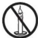
CANDLES OR OTHER OPEN FLAMES AWAY FROM THIS PRODUCT AT ALL TIMES.
NOTICE FOR CUSTOMERS IN THE UNITED KINGDOM
A moulded plug complying with BS1363 is fitted to this equipment for your safety and convenience.
Should the fuse in the plug supplied need to be replaced with the same rating of fuse approved by ASTA or BSI to BS 1362 (i.e., marked with ☑ or ) must be used.
If the plug supplied with this equipment has a detachable fuse cover, be sure to attach the fuse cover after you change the fuse. Never use the plug without the fuse cover. If you should lose the fuse cover, please contact your nearest Sony service station.
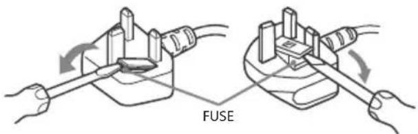
How to replace the fuse
Open the fuse compartment with a blade screwdriver, and replace the fuse.
Please refer to the illustration that actually equipped with the product.
IMPORTANT NOTICE
This product has been manufactured by or on behalf of Sony Corporation, 1-7-1 Konan Minato-ku Tokyo, 108-0075 Japan. Inquiries related to product compliance based on European Union legislation shall be addressed to the authorized representative, Sony Deutschland GmbH, Hedelfinger Strasse 61, 70327 Stuttgart, Germany. For any service or guarantee matters, please refer to the addresses provided in the separate service or guarantee documents.
Notice for Wireless Signal
Hereby, Sony Corporation declares that this unit is in compliance with the essential requirements and other relevant provisions of Directive 1999/5/EC.
For details, please access the following URL: http://www.compliance.sony.de/
Notice for customers: the following information is only applicable to equipment sold in countries applying EU directives.
TV wireless system may be operated in following countries:
AT, BE, HR, CY, CZ, DK, EE, FI, FR, DE, GR, HU, IE, IT, LV, LT, LU, MT, NL, PL, PT, SK, SI, ES, SE, GB, IS, LI, NO, CH, BG, RO, TR, AL, BA, MK, MD, RS, ME
This equipment can be operated in other non-European countries.
Safety information
WARNING
Batteries must not be exposed to excessive heat such as sunshine, fire or the like.
Installation/Set-up
Install and use the TV set in accordance with the instructions below in order to avoid any risk of fire, electrical shock or damage and/or injuries.
Installation
- The TV set should be installed near an easily accessible mains socket.
- Place the TV set on a stable, level surface to avoid it from falling down and cause personal injury or damage to the TV.
- Only qualified service personnel should carry out wall installations.
- For safety reasons, it is strongly recommended that you use Sony accessories, including:
— Wall-Mount Bracket
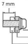
- Be sure to use the screws supplied with the Wall-Mount Bracket when attaching the Mounting Hooks (Stand) to the TV set. The supplied screws are designed as indicated by illustration when measured from the attaching surface of the Mounting Hook (Stand).
The diameter and length of the screws differ depending on the Wall-Mount Bracket model.
Use of screws other than those supplied may result in internal damage to the TV set or cause it to fall, etc.
Screw (supplied with the Wall-Mount Bracket)
Mounting Hook (Stand)
Hook attachment on rear of TV set
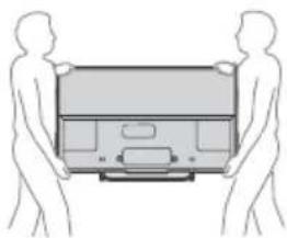
Transporting
- Before transporting the TV set, disconnect all cables.
- Two or three people are needed to transport a large TV set.
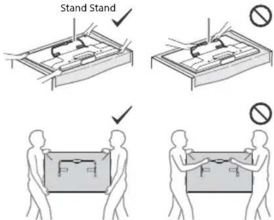
- When transporting the TV set by hand, hold it as shown below. Do not put stress on the LCD panel and the frame around the screen.
natural_image
Two human silhouettes carrying a rectangular device (no text or symbols visible)- When transporting the TV set, do not subject it to jolts or excessive vibration.
- When transporting the TV set for repairs or when moving, pack it using the original carton and packing material.
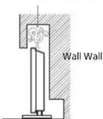
Topple prevention
- Before install the machine screw, lay the display face down on a stable work surface that is larger than the TV.
- To prevent damaging the surface of the LCD display, make sure to place a soft cloth on the work surface.
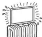
Ventilation
- Never cover the ventilation holes or insert anything in the cabinet.
- Leave space around the TV set as shown below.
- It is strongly recommended that you use a Sony Wall-Mount Bracket in order to provide adequate air-circulation.
Installed on the wall
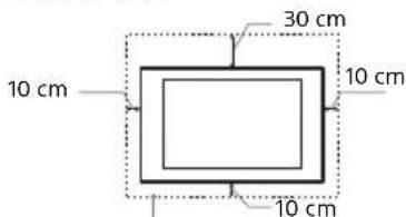
Leave at least this space around the set.
Installed with stand
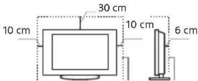
Leave at least this space around the set.
- To ensure proper ventilation and prevent the collection of dirt or dust:
— Do not lay the TV set flat, install upside down, backwards, or sideways.
— Do not place the TV set on a shelf, rug, bed or in a closet.
— Do not cover the TV set with a cloth, such as curtains, or items such as newspapers, etc.
— Do not install the TV set as shown below.
Air circulation is blocked.
Mains lead
Handle the mains lead and socket as follows in order to avoid any risk of fire, electrical shock or damage and/or injuries:
— Use only mains leads supplied by Sony, not other suppliers.
— Insert the plug fully into the mains socket.
— Operate the TV set on a 220-240 V AC supply only.
- When wiring cables, be sure to unplug the mains lead for your safety and take care not to catch your feet on the cables.
- Disconnect the mains lead from the mains socket before working on or moving the TV set.
— Keep the mains lead away from heat sources.
- Unplug the mains plug and clean it regularly. If the plug is covered with dust and it picks up moisture, its insulation may deteriorate, which could result in a fire.
Note
- Do not use the supplied mains lead on any other equipment.
- Do not pinch, bend, or twist the mains lead excessively. The core conductors may be exposed or broken.
- Do not modify the mains lead.
- Do not put anything heavy on the mains lead.
- Do not pull on the mains lead itself when disconnecting the mains lead.
- Do not connect too many appliances to the same mains socket.
- Do not use a poor fitting mains socket.
NOTE ON MAINS ADAPTOR
Warning
To reduce the risk of fire or electric shock, do not expose this apparatus to rain or moisture.
To prevent fire or shock hazard, do not place objects filled with liquids, such as vases, on the apparatus. Do not install this equipment in a confined space, such as a bookshelf or similar unit.
- Please ensure that the mains socket is installed near the equipment and shall be easily accessible.
- Be sure to use the supplied mains adaptor and mains lead.
- Do not use any other mains adaptor. It may cause a malfunction.
- Connect the mains adaptor to an easily accessible mains socket.
-
Do not coil the mains lead around the mains adaptor. The core wire may be cut and/or it may cause a malfunction of the media receiver.
-
Do not touch the mains adaptor with wet hands.
- If you notice an abnormality in the mains adaptor, disconnect it from the mains socket immediately.
- The set is not disconnected from the mains source as long as it is connected to the mains socket, even if the set itself has been turned off.
- As the mains adaptor will become warm when it is used for a long time, you may feel hot when touching it by hand.
Prohibited Usage
Do not install/use the TV set in locations, environments or situations such as those listed below, or the TV set may malfunction and cause a fire, electrical shock, damage and/or injuries.
Location:
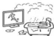
- Outdoors (in direct sunlight), at the seashore, on a ship or other vessel, inside a vehicle, in medical institutions, unstable locations, near water, rain, moisture or smoke.
- If the TV is placed in the changing room of a public bath or hot spring, the TV may be damaged by airborne sulphur, etc.
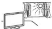
- For best picture quality, do not expose the screen to direct illumination or sunlight.
- Avoid moving the TV from a cold area to a warm area. Sudden room temperature changes may cause moisture condensation. This may cause the TV to show poor picture and/or poor colour. Should this occur, allow moisture to evaporate completely before powering the TV on.
Environment:
- Places that are hot, humid, or excessively dusty; where insects may enter; where it might be exposed to mechanical vibration, near flammable objects (candles, etc.). The TV set shall not be exposed to dripping or splashing and no objects filled with liquids, such as vases, shall be placed on the TV.
- Do not place the TV in a humid or dusty space, or in a room with oily smoke or steam (near cooking tables or humidifiers). Fire, electric shock, or warping may result.
- Do not install the TV in places subject to extreme temperature such as in direct sunlight, near a radiator or a heating vent. The TV may overheat in such condition which can cause deformation of the enclosure and/or TV malfunction.
Situation:
- Do not use when your hands are wet, with the cabinet removed, or with attachments not recommended by the manufacturer. Disconnect the TV set from mains socket and aerial during lightning storms.
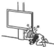
- Do not install the TV so that it sticks out into an open space. Injury or damage from a person or object bumping into the TV may result.
Broken pieces:
- Do not throw anything at the TV set. The screen glass may break by the impact and cause serious injury.
- If the surface of the TV set cracks, do not touch it until you have unplugged the mains lead. Otherwise electric shock may result.
When not in use
- If you will not be using the TV set for several days, the TV set should be disconnected from the mains for environmental and safety reasons.
- As the TV set is not disconnected from the mains when the TV set is just turned off, pull the plug from the mains to disconnect the TV set completely.
- However, some TV sets may have features that require the TV set to be left in standby to work correctly.
For children
- Do not allow children to climb on the TV set.
- Keep small accessories out of the reach of children, so that they are not mistakenly swallowed.
If the following problems occur...
Turn off the TV set and unplug the mains lead immediately if any of the following problems occur.
Ask your dealer or Sony service centre to have it checked by qualified service personnel.
When:
— Mains lead is damaged.
— Poor fitting of mains socket.
— TV set is damaged by being dropped, hit or having something thrown at it.
— Any liquid or solid object falls through openings in the cabinet.
About LCD Monitor Temperature
When the LCD Monitor is used for an extended period, the panel surrounds become warm. You may feel hot when touching there by the hand.
WALL-MOUNT BRACKET
Below information shows the correct handling of the Wall-Mount Bracket. Be sure to read this information thoroughly and use the Wall-Mount Bracket correctly.
To Customers:
Be sure to observe the following precautions for safety to prevent a serious injury through fire, electric shock, the product toppling over, or the product dropping.
- Be sure to subcontract the installation to licensed contractors and keep small children away during installation.
- Be sure to subcontract moving or dismounting of the TV to licensed contractors.
- Do not remove screws, etc., after mounting the TV.
- Do not make alterations to the parts of the Wall-Mount Bracket.
- Do not mount any equipment other than the specified product.
- Do not apply any load other than the TV on the Wall-Mount Bracket.
- Do not lean on or hang from the TV.
- Do not handle the TV with excessive force during cleaning or maintenance.
To Sony Dealers and Contractors:
The following instructions are for Sony dealers and contractors only. Be sure to read safety precautions described below and pay special attention to safety during the installation, maintenance and checking of this product.
- When handling or mounting the TV set, hold it on the sides. Do not lift the TV by the Stand.
- Do not install the Wall-Mount Bracket on wall surfaces where the corners or the sides of the TV are protruding away from the wall surface.
- Do not install the TV over or under an air conditioner.
- Be sure to install the Wall-Mount Bracket securely to the wall following the instructions in this instruction manual. If any of the screws are loose or fall out, the Wall-Mount Bracket may fall and cause injury or property damage.
- Be sure to use the supplied screws and attachment parts properly following the instructions given in this instruction manual. If you use substitute items, the TV may fall and cause bodily injury to someone or damage to
- Be sure to assemble the bracket properly following the instructed procedure explained in this instruction manual.
- Be sure to tighten the screws securely in the designated position.
- Be careful not to subject the TV to shock during installation.
- Do not allow the mains lead or the connecting cables to be pinched as the internal conductors may become exposed and cause a short circuit or an electrical break.
- Be sure to install the TV on a wall that is both perpendicular and flat.
• After proper installation of the TV, secure the cables properly.
Precautions
Viewing the TV
- Some people may experience discomfort (such as eye strain, fatigue, or nausea) while watching 3D video images or playing stereoscopic 3D games. Sony recommends that all viewers take regular breaks while watching 3D video images or playing stereoscopic 3D games. The length and frequency of necessary breaks will vary from person to person. You must decide what works best. If you experience any discomfort, you should stop watching the 3D video images or playing stereoscopic 3D games until the discomfort ends; consult a doctor if you believe necessary. You should also review (i) the instruction manual of any other device or media used with this television and (ii) our website (http://support.sony-europe.com/) for the latest information. The vision of young children (especially those under six years old) is still under development. Consult your doctor (such as a paediatrician or eye doctor) before allowing young children to watch 3D video images or play stereoscopic 3D games. Adults should supervise young children to ensure they follow the recommendations listed above.
- Do not use, store, or leave the 3D Glasses or battery near fire, or in places with a high temperature, e.g., in direct sunlight, or in sun-heated cars.
- When using the simulated 3D function, please note that the displayed image is modified from the original due to the conversion done by this television.
• View the TV in moderate light, as viewing the TV in poor light or during long period of time, strains your eyes. - When using headphones, adjust the volume so as to avoid excessive levels, as hearing damage may result.
LCD Screen
- Although the LCD screen is made with high-precision technology and 99.99% or more of the pixels are effective, black dots may appear or bright points of light (red, blue, or green) may appear constantly on the LCD screen. This is a structural property of the LCD screen and is not a malfunction.
- Do not push or scratch the front filter, or place objects on top of this TV set. The image may be uneven or the LCD screen may be damaged.
- If this TV set is used in a cold place, a smear may occur in the picture or the picture may become dark. This does not indicate a failure. These phenomena disappear as the temperature rises.
- Ghosting may occur when still pictures are displayed continuously. It may disappear after a few moments.
- The screen and cabinet get warm when this TV set is in use. This is not a malfunction.
- The LCD screen contains a small amount of liquid crystal. Follow your local ordinances and regulations for disposal.
Handling and cleaning the screen surface/cabinet of the TV set
Be sure to unplug the mains lead connected to the TV set from mains socket before cleaning.
To avoid material degradation or screen coating degradation, observe the following precautions.
- To remove dust from the screen surface/cabinet, wipe gently with a soft cloth. If dust is persistent, wipe with a soft cloth slightly moistened with a diluted mild detergent solution.
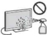
- Never spray water or detergent directly on the TV set. It may drip to the bottom of the screen or exterior parts and enter the TV set, and may cause damage to the TV set.
- Never use any type of abrasive pad, alkaline/acid cleaner, scouring powder, or volatile solvent, such as alcohol, benzene, thinner or insecticide. Using such materials or maintaining prolonged contact with rubber or vinyl materials may result in damage to the screen surface and cabinet material.
• Periodic vacuuming of the ventilation openings is recommended to ensure to proper ventilation. - When adjusting the angle of the TV set, move it slowly so as to prevent the TV set from moving or slipping off from its table stand.
Optional Equipment
- Keep optional components or any equipment emitting electromagnetic radiation away from the TV set. Otherwise picture distortion and/or noisy sound may occur.
- This equipment has been tested and found to comply with the limits set out in the EMC Directive using a connection signal cable shorter than 3 meters.
Recommendation of F-type plug
Projection of the inner wire from the connection part must be less than 1.5 mm.

(Reference drawing of the F type plug)
Caution about handling the remote control
- Observe the correct polarity when inserting batteries.
- Do not use different types of batteries together or mix old and new batteries.
- Dispose of batteries in an environmentally friendly way. Certain regions may regulate the disposal of batteries. Please consult your local authority.
- Handle the remote control with care. Do not drop or step on it, or spill liquid of any kind onto it.
- Do not place the remote control in a location near a heat source, a place subject to direct sunlight, or a damp room.
Wireless Function of the unit
- Do not operate this unit near medical equipment (pacemaker, etc.), as malfunction of the medical equipment may result.
- Although this unit transmits/receives scrambled signals, be careful of unauthorised interception. We cannot be responsible for any trouble as a result.
WALL-MOUNT BRACKET
- If you use the TV installed on the Wall-Mount Bracket for a long time, the wall behind or above the TV may become discoloured or the wallpaper may come unglued, depending on the material of the wall.
- If the Wall-Mount Bracket is removed after installing it on the wall, the screw holes remain.
- Do not use the Wall-Mount Bracket in a place where it is subjected to mechanical vibration.
Disposal of the TV set
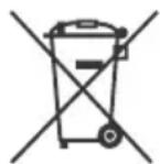
Disposal of Old Electrical & Electronic Equipment (Applicable in the European Union and other European countries with separate collection systems)
This symbol on the product or on its packaging indicates that this product shall not be treated as household waste. Instead it shall be handed over to the applicable collection point for the
recycling of electrical and electronic equipment. By ensuring this product is disposed of correctly, you will help prevent potential negative consequences for the environment and human health, which could otherwise be caused by inappropriate waste handling of this product. The recycling of materials will help to conserve natural resources. For more detailed information about recycling of this product, please contact your local Civic Office, your household waste disposal service or the shop where you purchased the product.
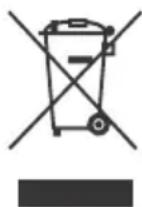
Disposal of waste batteries (applicable in the European Union and other European countries with separate collection systems)
This symbol on the battery or on the packaging indicates that the battery provided with this
product shall not be treated as household waste. On certain batteries this symbol might be used in combination with a chemical symbol. The chemical symbols for mercury (Hg) or lead (Pb) are added if the battery contains more than 0.0005% mercury or 0.004% lead. By ensuring these batteries are disposed of correctly, you will help prevent potentially negative consequences for the environment and human health which could otherwise be caused by inappropriate waste handling of the battery. The recycling of the materials will help to conserve natural resources. In case of products that for safety, performance or data integrity reasons require a permanent connection with an incorporated battery, this battery should be replaced by qualified service staff only. To ensure that the battery will be treated properly, hand over the product at end-of-life to the applicable collection point for the recycling of electrical and electronic equipment. For all other batteries, please view the section on how to remove the battery from the product safely. Hand the battery over to the applicable collection point for the recycling of waste batteries. For more detailed information about recycling of this product or battery, please contact your local Civic Office, your household waste disposal service or the shop where you purchased the product.
Installing the TV to the Wall
To Customers
Sufficient expertise is required for installing this product. Be sure to subcontract the installation to Sony dealers or licensed contractors and pay special attention to safety during the installation. Sony is not liable for any damages or injury caused by mishandling or improper installation, or installing any other than the specified product. Your Statutory Rights (if any) are not affected.
To Sony Dealers and Contractors
Sufficient expertise is required for installing this product. Be sure to read this instruction manual thoroughly to do the installation work safely. Sony is not liable for any damages or injury caused by mishandling or improper installation.
Your TV's Table-Top Stand will be used as a part of the Wall-Mount Bracket.
Note
- See page 3 (Safety information) and page 5 (Precautions) on WALL-MOUNT BRACKET before carrying out Wall-Mount Bracket installation.
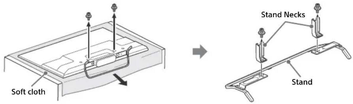
- If the Table-Top Stand is attached to the TV, detach the Table-Top Stand beforehand.
- Place the TV with its screen facing down on a flat and stable surface covered with a thick and soft cloth that is larger than the TV, when securing the Stand or when removing the Table-Top Stand from the TV to prevent damaging the surface of the LCD display.
- Once the Stand Necks are detached from the Stand, be sure to keep the Stand Necks and screws in a safe place.
- When attaching the Table-Top Stand again, be sure to fasten the screws (previously removed) to the original holes on the rear of the TV.
- Be sure the TV is on the vertical position before switching on. TV set must not powered on with LCD panel face down to avoid uneven picture uniformity.
To detach the Table-Top Stand from the TV
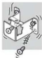
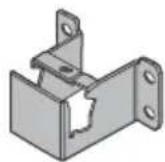
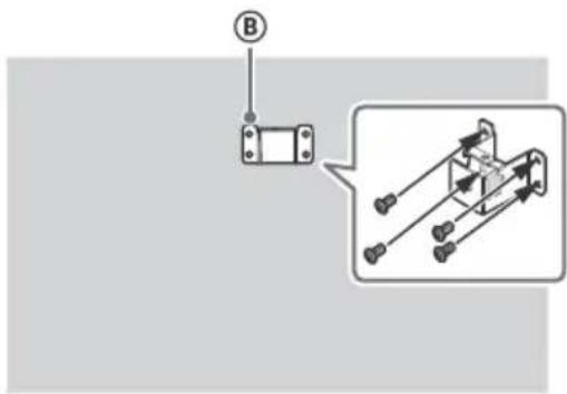
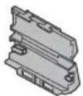
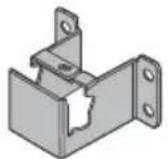
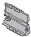
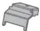
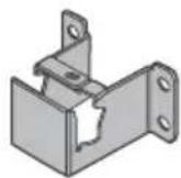
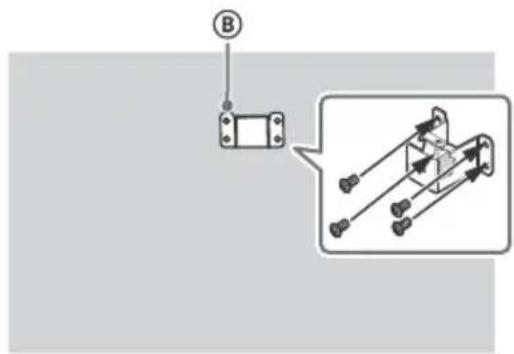
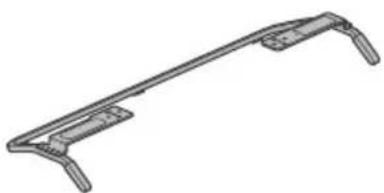
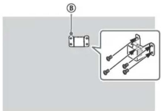
Installing the Brackets on the wall
1 Prepare necessary items.
Wall-Mount Bracket accessories (supplied)
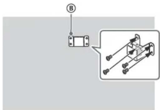
Ⓐ Paper Template Ⓑ Wall-Mount Base
KDL-50W82xB,
KDL-50W81xB,
KDL-50W80xB,
KDL-50W70xB (2)
KDL-42W82xB,
KDL-42W81xB,
KDL-42W80xB,
KDL-42/32W70xB (1)
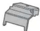
© Stand Protector
KDL-50W82xB,
KDL-50W81xB,
KDL-50W80xB,
KDL-50W70xB (2)
KDL-42W82xB,
KDL-42W81xB,
KDL-42W80xB,
KDL-42/32W70xB (1)

D Screw
(+PSW 6 × 12) (2)

E Spacer (2) F Bracket Cap Plate
KDL-50W82xB,
KDL-50W81xB,
KDL-50W80xB,
KDL-50W70xB (2)
KDL-42W82xB,
KDL-42W81xB,
KDL-42W80xB,
KDL-42/32W70xB (1)
© Screw (+PSW 4 × 10)
KDL-50W82xB,
KDL-50W81xB,
KDL-50W80xB,
KDL-50W70xB (2)
KDL-42W82xB,
KDL-42W81xB
KDL-42W80xB,
KDL-42/32W70xB (1)

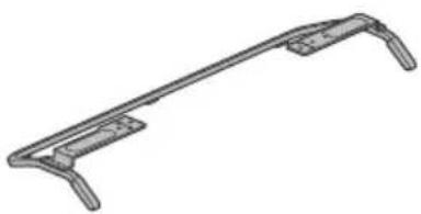
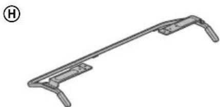
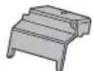
Stand (supplied)
H

natural_image
Technical line drawing of a mechanical bracket or clamp (no text or symbols)Screws for Wall-Mount Base (8 mm in diameter, not supplied)
KDL-50W82xB,
KDL-50W81xB,
KDL-50W80xB,
KDL-50W70xB (8)
KDL-42W82xB,
KDL-42W81xB,
KDL-42W80xB
KDL-42/32W70xB (4)
2 Make sure that the wall has enough space and is capable of supporting a weight of at least four times that of the TV.
Refer to the following table on installing the TV to the wall. See page 15-17 (Specifications) for the TV's weight.
KDL-50W82xB, KDL-50W81xB, KDL-50W80xB, KDL-50W70xB
KDL-42W82xB, KDL-42W81xB, KDL-42W80xB, KDL-42/32W70xB
Unit: cm
| Model NameKDL- | Display dimensions Screen centre dimension Length for mounting | ||||
| a | b | c | d | e | |
| 50W82xB/50W81xB/50W80xB/50W70xB | 111.6 | 65.6 | 13.0 | 46.9 | 11.8 |
| 42W82xB/42W81xB/42W80xB/42W70xB | 95.8 | 56.3 | 17.5 | 46.5 | 11.8 |
| 32W70xB 72.9 | 43.3 | 18.8 | 41.3 | 11.3 | |
Note
- Figures in the table may differ slightly depending on the installation.
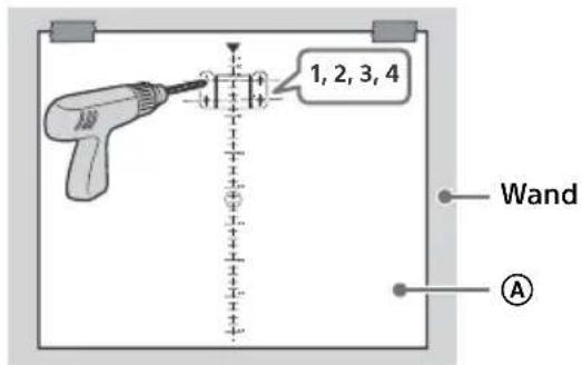
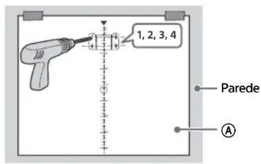
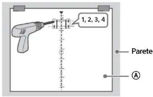
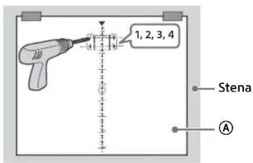
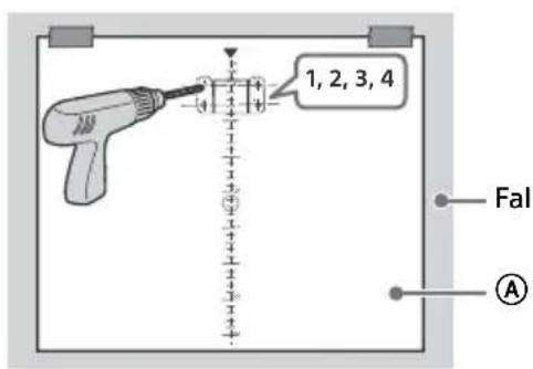
3 Make a mark on the Paper Template Ⓐ that indicates the centre of the screen for your TV.
KDL-50W82xB, KDL-50W81xB, KDL-50W80xB, KDL-50W70xB
KDL-42W82xB, KDL-42W81xB, KDL-42W80xB, KDL-42/32W70xB
Scale on Paper Template Ⓐ
Scale on Paper Template Ⓐ
Mark for KDL-50W82xB, KDL-50W81xB, KDL-50W80xB, KDL-50W70xB
4 Tape the Paper Template Ⓐ to the wall and drill holes according to the numbering on the Paper Template Ⓐ using an electric drill.
KDL-50W82xB, KDL-50W81xB, KDL-50W80xB, KDL-50W70xB
KDL-42W82xB, KDL-42W81xB, KDL-42W80xB, KDL-42/32W70xB
5 Remove the Paper Template Ⓐ off from the wall.
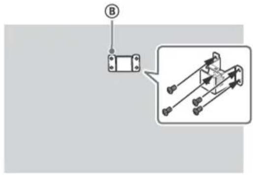
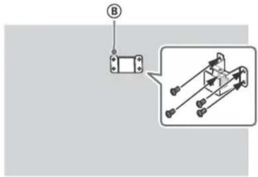
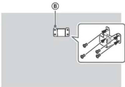
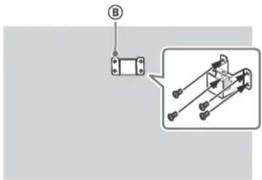
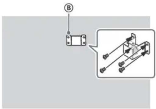
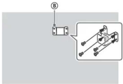
6 Attach the Wall-Mount Base Ⓑ to the wall correctly using the screws (8 mm in diameter, not supplied).
KDL-50W82xB, KDL-50W81xB, KDL-50W80xB, KDL-50W70xB
KDL-42W82xB, KDL-42W81xB, KDL-42W80xB, KDL-42/32W70xB
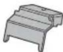
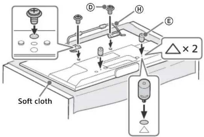
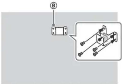
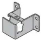
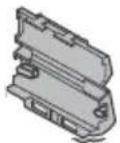
1 Remove screws from the rear of the TV. Be sure to store the removed screws in a safe place, keeping them away from children.

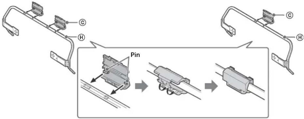
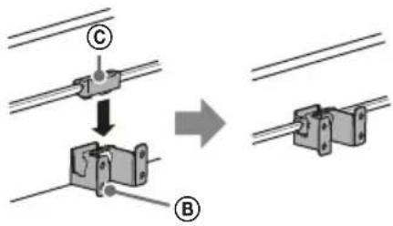
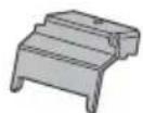
2 Insert the pin (on the Stand Protector ©) into the hole on the Stand Ⓗ, then fold up the Stand Protector ©. Confirm the Stand Protector © is firmly latched to the Stand Ⓗ.
KDL-50W82xB, KDL-50W81xB, KDL-50W80xB, KDL-50W70xB
KDL-42W82xB, KDL-42W81xB, KDL-42W80xB, KDL-42/32W70xB
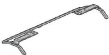
3 Attach the stand Ⓗ to the TV using the supplied screws Ⓓ. Attach the Spacers Ⓔ to the holes indicated by the triangle marks △. KDL-50W82xB, KDL-50W81xB, KDL-50W80xB, KDL-50W70xB is used for illustration purpose.
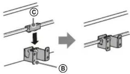
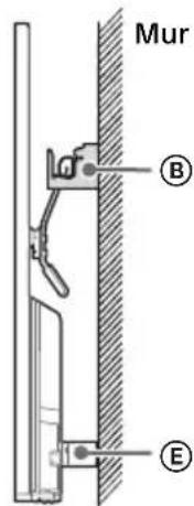
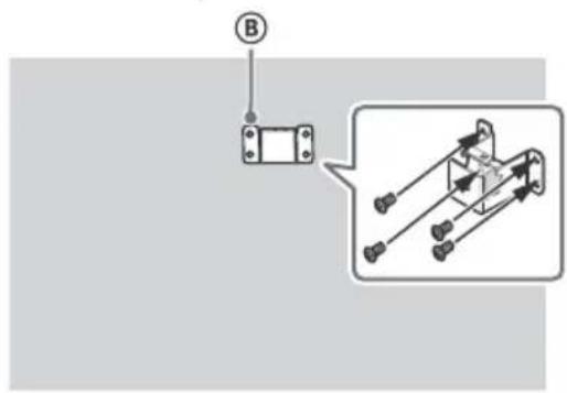
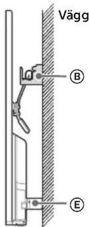
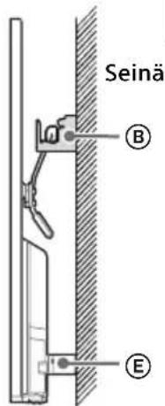
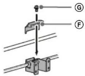
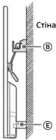
Installing the TV on the wall
1 Make sure to connect and bundle the cables before installing the TV on the wall.
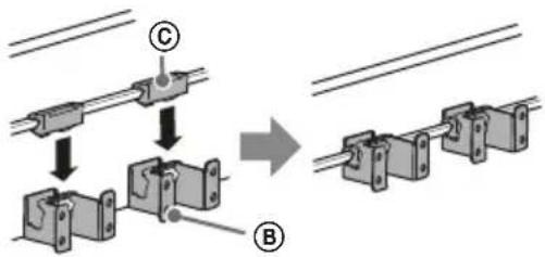
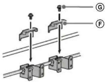
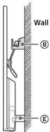
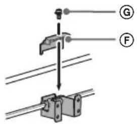
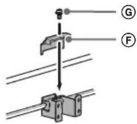
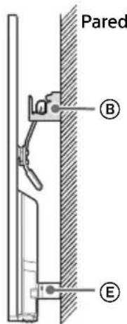
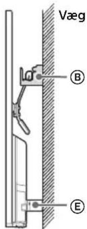
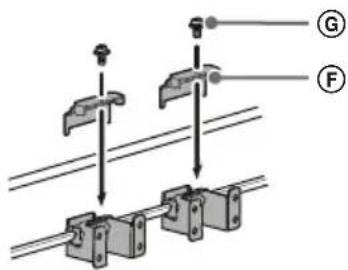
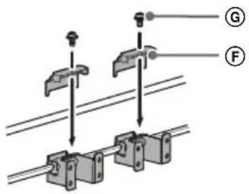
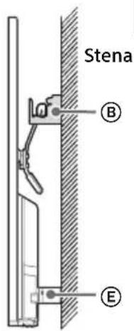
2 Install the TV on the wall. Then, confirm the Stand Protector © is firmly latched into the Wall-Mount Base ® and the Spacers ® touch the wall. Attach the Bracket Cap Plate ® using the supplied screws Ⓖ.

KDL-50W82xB, KDL-50W81xB, KDL-50W80xB, KDL-50W70xB
1
KDL-42W82xB, KDL-42W81xB, KDL-42W80xB, KDL-42/32W70xB
1


2
2

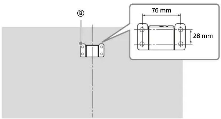
Dimensions of the hole positions on the wall
Provide the following information to the licensed contractors if necessary.
Use screws (8 mm in diameter, not supplied) to install the Wall-Mount Base Ⓑ on the wall.
Be sure to use the supplied Paper Template Ⓐ that shows the actual position of Wall-Mount Base for easy installation.
KDL-50W82xB, KDL-50W81xB, KDL-50W80xB, KDL-50W70xB
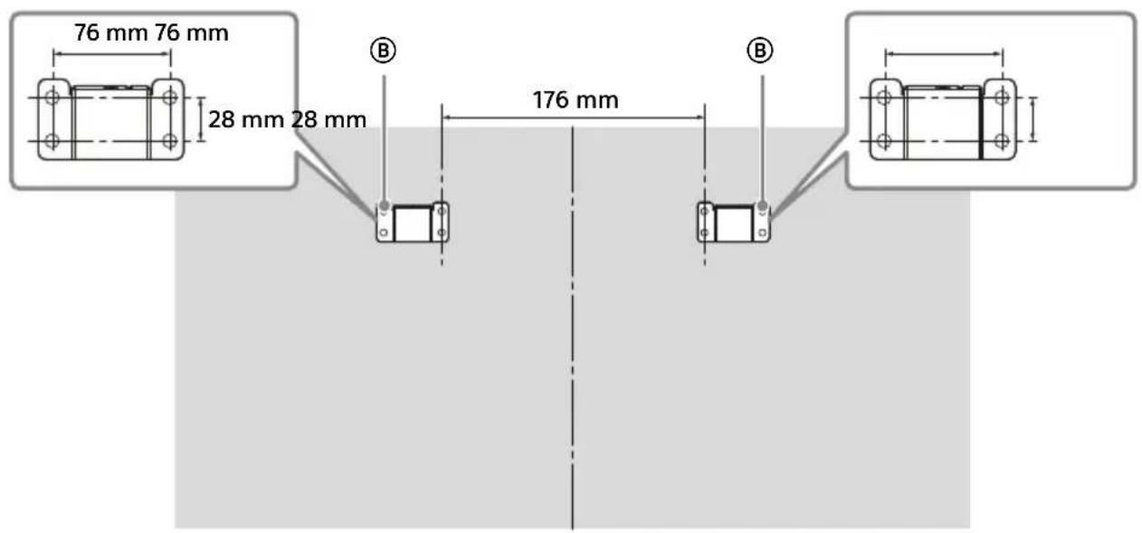
KDL-42W82xB, KDL-42W81xB, KDL-42W80xB, KDL-42/32W70xB

For instructions on Wall-Mount Bracket installation of your TV model, refer to the following website: www.sony.eu/tv/wall-mount-bracket-manual
Troubleshooting
When the illumination LED is flashing in red, count how many times it flashes (interval time is three seconds).
If the illumination LED flashes red, reset the TV by disconnecting the mains lead from the TV for two minutes, then turn on the TV.
If the problem persists, contact your dealer or Sony service centre with the number of times the Illumination LED flashes red (interval time is three seconds). Press I/⏻ on the TV to turn it off, disconnect the mains lead, and inform your dealer or Sony service centre.
When the illumination LED is not flashing, check the items as follows.
You can also refer to [Troubleshooting] in the i-Manual or perform self-diagnosis by selecting ? [Help] → [Customer Support] → [Self Diagnostics]. If the problem persists, have your TV serviced by qualified service personnel.
Troubles and Solutions
There is no picture (screen is dark) and no sound.
- Check the antenna (aerial)/cable connection.
- Connect the TV to AC power (mains), and press I/ ⏻ on the TV or remote.
Some programmes cannot be tuned.
- Check the antenna (aerial) or dish.
- The satellite cable might be short-circuited or there might be connection problems of the cable. Check the cable connection and then turn the TV off with the Mains power On/Off switch, and turn it on again.
- The frequency that you entered is out of range. Consult the received satellite broadcasting company.
There is no Cable TV services (programmes) found.
- Check the cable connection or tuning configuration.
- Attempt the [Digital Auto Tuning] by selecting [Antenna] instead of [Cable].
The remote does not function.
- Replace the batteries.
- Your TV may be in SYNC mode.
Press SYNC MENU, select [TV Control] and then select [Home (Menu)] or [Options] to control the TV.
The [Parental Lock] password has been forgotten.
- Enter 9999 for the PIN code. (PIN code 9999 is always accepted.)
The TV surrounds become warm.
- When the TV is used for an extended period, the TV surrounds become warm. You may feel hot when touching there by the hand.
Frozen audio or video, a blank screen, or the TV does not respond to TV or remote buttons.
- Perform a simple reset of the TV by unplugging the AC power cord for two minutes, then plug it in again.
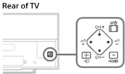
The I/∅, CH+/-, ∠+/-, ↑/↓/↔/→, →, ⊕ and HOME buttons cannot be located on the TV.
- See below illustration for location of the buttons on the TV.
The illumination LED is turned on.
- If you do not wish to light up the illumination LED, you can turn it off.
Press HOME, then select [Settings] →
[System Settings] → [General Set-up] →
[Illumination LED] → [Off]. You can also press
OPTIONS, then select [Illumination LED] → [Off].
Cannot connect to a wireless router by WPS.
- If you use WEP security, select [Easy] [Wi-Fi] [Connect by scan list].
Then, select the network name (SSID) you want to connect.
Cannot find the required network name in network setup.
- Select [[Manual Entry]] and press ⓣ to enter network name.
Specifications
System
Panel system
LCD (Liquid Crystal Display) Panel, LED Backlight
TV system
Analogue: Depending on your country/area
selection: B/G, D/K, L, I, M
Digital: DVB-T/DVB-C
DVB-T2
Satellite: DVB-S/DVB-S2
Colour/video system
Analogue: PAL, SECAM, NTSC3.58, NTSC4.43
Digital: Refer to the i-Manual.
Channel coverage
Analogue: UHF/VHF/Cable, Depending on your country/area selection.
Digital: UHF/VHF/Cable, Depending on your country/area selection.
Satellite: IF Frequency 950-2150 MHz
Sound output
8 W + 8 W (except KDL-32W70xB)
5 W + 5 W (KDL-32W70xB only)
Wireless technology
Protocol IEEE802.11a/b/g/n
Input/Output jacks
Antenna (aerial) cable
75 ohm external terminal for VHF/UHF
Satellite antenna
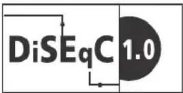
Female F-Type Connector IEC169-24, 75 ohm. DiSEqC 1.0, LNB 13 V/18 V & 22 kHz tone, Single Cable Distribution EN50494.
↔ /→ AV1
21-pin scart connector (CENELEC standard) including audio/video input, RGB input and TV audio/video output.
- / - C O M P O N E N
YPBPR (Component Video): 1080p (50, 60 Hz), 1080i (50, 60 Hz), 720p (50, 60 Hz), 576p, 576i, 480p, 480i
Audio input (phono jacks)
→ AV2
Video input (common phono pin with Y input)
HDMI IN 1, 2, 3, 4 (except KDL-50/42/32W70xB)
Video (2D): 1080p (30, 50, 60 Hz), 1080/24p, 1080i (50, 60 Hz), 720p (30, 50, 60 Hz), 720/24p, 576p, 576i, 480p, 480i, PC Formats
Video (3D):
Frame Packing: 1080p (30 Hz), 1080/24p, 1080i (50, 60 Hz), 720p (30, 50, 60 Hz), 720/24p
Side-by-Side: 1080p (50, 60 Hz), 1080/24p, 1080i (50, 60 Hz), 720p (50, 60 Hz)
Over-Under: 1080p (30, 50, 60 Hz), 1080/24p, 1080i (50, 60 Hz), 720p (50, 60 Hz)
Audio: 5.1 channel linear PCM: 32, 44.1 and
48 kHz, 16, 20 and 24 bits, Dolby Digital
ARC (Audio Return Channel) (HDMI IN 2 only)
HDMI IN 1, 2, 3, 4 (KDL-50/42/32W70xB only)
Video: 1080p (30, 50, 60 Hz), 1080/24p, 1080i (50, 60 Hz), 720p (30, 50, 60 Hz), 720/24p, 576p, 576i, 480p, 480i, PC Formats
Audio: 5.1 channel linear PCM: 32, 44.1 and 48 kHz, 16, 20 and 24 bits, Dolby Digital ARC (Audio Return Channel) (HDMI IN 2 only
MHL (common with HDMI IN 1)
(except KDL-50/42/32W70xB)
Video (2D): 1080p (30 Hz), 1080/24p, 1080i (50, 60 Hz), 720p (30, 50, 60 Hz), 720/24p, 576p, 576i, 480p, 480i
Video (3D):
Side-by-Side: 1080/24p, 1080i (50, 60 Hz), 720p (50, 60 Hz)
Over-Under: 1080p (30 Hz), 1080/24p, 1080i (50, 60 Hz), 720p (50, 60 Hz)
Audio: 5.1 channel linear PCM: 32, 44.1 and 48 kHz, 16, 20 and 24 bits, Dolby Digital
MHL (common with HDMI IN 1)
(KDL-50/42/32W70xB only)
Video: 1080p (30 Hz), 1080/24p, 1080i (50, 60 Hz), 720p (30, 50, 60 Hz), 720/24p, 576p, 576i, 480p, 480i
Audio: 5.1 channel linear PCM: 32, 44.1 and 48 kHz, 16, 20 and 24 bits, Dolby Digital
DIGITAL AUDIO OUT (OPTICAL)
Digital optical jack (Two channel linear PCM, Dolby Digital)
AUDIO OUT/Ω
Headphone jack (supports Subwoofer out)
ψ1 (HDD REC), ♦
USB HDD device port ( only ), USB port
图
CAM (Conditional Access Module) slot
- C + DC IN 19.5 V
AC adapter input
LAN
10BASE-T/100BASE-TX connector (Depending on the operating environment of the network, connection speed may differ. 10BASE-T/100BASE-TX communication rate and communication quality are not guaranteed for this TV.)
Others
Optional accessories
Touchpad Remote Control: RMF-ED004
Camera and Microphone Unit: CMU-BR200/CMU-BR100
Wireless subwoofer: SWF-BR100
MHL cable: DLC-MB10/DLC-MB20/DLC-MC10/DLC-MC20
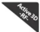
Active 3D Glasses: TDG-BT500A (KDL-50W82xB, KDL-50W81xB, KDL-50W80xB only)
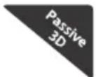
Passive 3D Glasses: TDG-500P (KDL-42W82xB, KDL-42W81xB, KDL-42W80xB only)
Operating temperature
0^ C - 40^ C
Operating humidity
10% - 80% RH (non-condensing)
Power and others
Power requirements
19.5 V DC with AC adapter
Rating: Input 220 V - 240 V AC, 50 Hz
Energy Efficiency Class
Screen size (measured diagonally) (Approx.)
Average annual energy consumption ^1
Standby power consumption ^*2
0.5 W (10 W in software/EPG update mode)
Display resolution
1,920 dots (horizontal) × 1,080 lines (vertical)
Dimensions (Approx.) (w × h × d)
with Table-Top Stand
with Table-Top Stand
*1 Energy consumption per year, based on the power consumption of the television operating 4 hours per day for 365 days. The actual energy consumption will depend on how the television is used.
*2 Specified standby power is reached after the TV finishes necessary internal processes.
Note
- The "x" that appears in the model name corresponds to a numeric digit, related to design, colour or TV system.
- Do not remove the dummy card from TV CAM (Conditional Access Module) slot other than to insert a smart card fitted in CAM.
- Optional accessories availability depends on countries/region/TV model/stock.
- Design and specifications are subject to change without notice.
- This TV set incorporates MHL 2.
Notes on Digital TV function
- Any functions related to Digital TV ( ) DVB only work in countries or areas where DVB-T/DVB-T2 (MPEG-2 and H.264/MPEG-4 AVC) digital terrestrial signals are broadcast or where you have access to a compatible DVB-C (MPEG-2 and H.264/MPEG-4 AVC) cable service. Please confirm with your local dealer if you can receive a DVB-T/ DVB-T2 signal where you live or ask your cable provider if their DVB-C cable service is suitable for integrated operation with this TV.
- Your cable provider may charge a fee for their services, or require you to agree to its terms and conditions of business.
- This TV set complies with DVB-T/DVB-T2 and DVB-C specifications, but compatibility with future DVB-T/DVB-T2 digital terrestrial and DVB-C digital cable broadcasts are not guaranteed.
- Some Digital TV functions may not be available in some countries/areas and DVB-C cable may not operate correctly with some providers.
Trademark information
- The terms HDMI and HDMI High-Definition Multimedia Interface, and the HDMI Logo are trademarks or registered trademarks of HDMI Licensing LLC in the United States and other countries.
- DLNA ^ , the DLNA Logo and DLNA CERTIFIED ^ are trademarks, service marks, or certification marks of the Digital Living Network Alliance.
- Manufactured under license from Dolby Laboratories. Dolby and the double-D symbol are trademarks of Dolby Laboratories.
- "BRAVIA" and BareTrademarks of Sony Corporation.
- TrackID is a trademark or registered trademark of Sony Mobile Communications AB.
-
Gracenote, Gracenote eyeQ, Gracenote VideoID, Gracenote Video Explore, Gracenote MusicID, the Gracenote logo and logotype, and the "Powered by Gracenote" logo are either registered trademarks or trademarks of Gracenote in the United States and/or other countries.
-
Opera® Devices SDK from Opera Software ASA. Copyright 1995-2014 Opera Software ASA. All rights reserved.
- Wi-Fi, Wi-Fi Direct and Miracast are trademarks or registered trademarks of Wi-Fi Alliance.
- "Sony Entertainment Network logo" and "Sony Entertainment Network" are trademarks of Sony Corporation.
- MHL, Mobile High-Definition Link and the MHL Logo are trademarks or registered trademarks of MHL Licensing, LLC.
- For DTS patents, see http://patents.dts.com. Manufactured under license from DTS Licensing Limited. DTS, the Symbol, & DTS and the Symbol together are registered trademarks, and DTS Digital Surround is a trademark of DTS, Inc. © DTS, Inc. All Rights Reserved.
- Designed with UEI Technology™ Under License from Universal Electronics Inc. Portions © UEI 2000 – 2013
- The Bluetooth® word mark and logos are owned by the Bluetooth SIG, Inc. and any use of such marks by Sony Corporation is under license. Other trademarks and trade names are those of their respective owners.
- DiSEqC™ is a trademark of EUTELSAT. This TV supports DiSEqC 1.0. This TV is not intended for controlling motorized antennas.
Table des matières
AVIS IMPORTANT....2
natural_image
Line drawing of two human figures carrying a rectangular object (no text or symbols)© Protection du support
KDL-50W82xB,
KDL-50W81xB.
KDL-50W80xB,
KDL-50W70xB (2)
KDL-42W82xB,
KDL-42W81xB,
KDL-42W80xB,
KDL-42/32W70xB (1)
D Vis
(+PSW 6 × 12) (2)

⑤ Entretoise (2)
⑤ Plaque
natural_image
Technical line drawing of a mechanical bracket or clamp (no text or symbols)KDL-42W82xB, KDL-42W81xB, KDL-42W80xB, KDL-42/32W70xB
2

KDL-42W82xB, KDL-42W81xB, KDL-42W80xB, KDL-42/32W70xB
1
2
-∅/→C O M P O N E N T I
YP _B PR (Vidéo composante) : 1080p (50, 60 Hz), 1080i (50, 60 Hz), 720p (50, 60 Hz), 576p, 576i, 480p, 480i
Entrée audio (prises phono)
AV2
DIGITAL AUDIO OUT (OPTICAL)
natural_image
Two human silhouettes holding a rectangular device, no text or symbols visible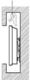
© Tornillo (+PSW 4 × 10)
KDL-50W82xB,
KDL-50W81xB,
KDL-50W80xB,
KDL-50W70xB (2)
KDL-42W82xB,
KDL-42W81xB,
KDL-42W80xB,
KDL-42/32W70xB (1)

Base (suministrada)
H
natural_image
Technical line drawing of a mechanical bracket or clamp (no text or symbols)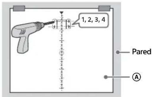
KDL-42W82xB, KDL-42W81xB, KDL-42W80xB, KDL-42/32W70xB
1
2

2
natural_image
Simple line drawing of a Sony air conditioner unit with no text or symbols1080/24p, 1080i (50, 60 Hz), 720p (50, 60 Hz)
Encima-debajo: 1080p (30, 50, 60 Hz), 1080/24p, 1080i (50, 60 Hz), 720p (50, 60 Hz)
DIGITAL AUDIO OUT (OPTICAL)
Toma digital óptica (PCM lineal de dos canales, Dolby Digital)
→ AUDIO OUT/Ω
natural_image
Two human figures holding a rectangular device, no text or symbols visible© Schroef (+PSW 4 × 10)
KDL-50W82xB,
KDL-50W81xB,
KDL-50W80xB,
KDL-50W70xB (2)
KDL-42W82xB,
KDL-42W81xB,
KDL-42W80xB
KDL-42/32W70xB (1)

natural_image
Technical line drawing of a mechanical bracket or clamp (no text or symbols)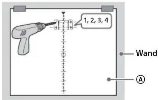
Video (2D): 1080p (30 Hz), 1080/24p,
1080i (50, 60 Hz), 720p (30, 50, 60 Hz),
720/24p, 576p, 576i, 480p, 480i
Video (3D):
Naast elkaar: 1080/24p, 1080i (50, 60 Hz),
720p (50, 60 Hz)
Boven elkaar: 1080p (30 Hz), 1080/24p,
1080i (50, 60 Hz), 720p (50, 60 Hz)
Audio: 5.1-kanaals lineair PCM: 32, 44,1 en
48 kHz, 16, 20 en 24 bits, Dolby Digital
DIGITAL AUDIO OUT (OPTICAL)
natural_image
Line drawing of two human figures holding a rectangular device (no text or symbols)© Schraube (+PSW 4 × 10)
KDL-50W82xB,
KDL-50W81xB,
KDL-50W80xB,
KDL-50W70xB (2)
KDL-42W82xB,
KDL-42W81xB,
KDL-42W80xB,
KDL-42/32W70xB (1)

natural_image
Technical line drawing of a mechanical clamp or bracket (no text or symbols)KDL-42W82xB, KDL-42W81xB, KDL-42W80xB, KDL-42/32W70xB
KDL-42W82xB, KDL-42W81xB, KDL-42W80xB, KDL-42/32W70xB
DIGITAL AUDIO OUT (OPTICAL)
natural_image
Two human silhouettes holding a rectangular device, no text or symbols visibleCabo de alimentação
(D) Parafuso (+PSW 6 × 12) (2)


natural_image
Technical line drawing of a mechanical bracket or clamp (no text or symbols)KDL-42W82xB, KDL-42W81xB, KDL-42W80xB, KDL-42/32W70xB
KDL-42W82xB, KDL-42W81xB, KDL-42W80xB, KDL-42/32W70xB
16, 20 e 24 bits, Dolby Digital
ARC (Audio Return Channel) (apenas HDMI IN 2)
HDMI IN 1, 2, 3, 4 (apenas KDL-50/42/32W70xB)
Vídeo: 1080p (30, 50, 60 Hz), 1080/24p,
1080i (50, 60 Hz), 720p (30, 50, 60 Hz),
720/24p, 576p, 576i, 480p, 480i, Formatos PC
16, 20 e 24 bits, Dolby Digital
ARC (Audio Return Channel) (apenas HDMI IN 2)
MHL (normal com HDMI IN 1)
(exceto para KDL-50/42/32W70xB)
Vídeo (2D): 1080p (30 Hz), 1080/24p, 1080i
(50, 60 Hz), 720p (30, 50, 60 Hz), 720/24p, 576p,
576i, 480p, 480i
Vídeo (3D):
Lado-a-lado: 1080/24p, 1080i (50, 60 Hz),
720p (50, 60 Hz)
16, 20 e 24 bits, Dolby Digital
MHL (normal com HDMI IN 1)
(apenas KDL-50/42/32W70xB)
Vídeo: 1080p (30 Hz), 1080/24p, 1080i (50, 60 Hz),
720p (30, 50, 60 Hz), 720/24p, 576p, 576i, 480p, 480i
16, 20 e 24 bits, Dolby Digital
DIGITAL AUDIO OUT (OPTICAL)
Tomada digital ótica (PCM linear de dois canais, Dolby Digital)
→ AUDIO OUT/Ω
Saída de áudio (minitomada estéreo)
natural_image
Two silhouettes of people carrying a rectangular device (no text or symbols visible)natural_image
Two human figures carrying a rectangular object, one marked with a checkmark (no text or symbols present)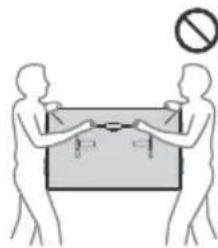
(D) Vite (+PSW 6 × 12) (2)

© Vite (+PSW 4 × 10)
KDL-50W82xB, KDL-50W81xB, KDL-50W80xB, KDL-50W70xB (2) KDL-42W82xB, KDL-42W81xB, KDL-42W80xB, KDL-42/32W70xB (1)

natural_image
Technical line drawing of a mechanical bracket or clamp (no text or symbols)KDL-42W82xB, KDL-42W81xB, KDL-42W80xB, KDL-42/32W70xB
KDL-42W82xB, KDL-42W81xB, KDL-42W80xB, KDL-42/32W70xB
Frame Packing: 1080p (30 Hz), 1080/24p,
1080i (50, 60 Hz), 720p (30, 50, 60 Hz), 720/24p
Fianco a fianco: 1080p (50, 60 Hz),
1080/24p, 1080i (50, 60 Hz), 720p (50, 60 Hz)
Sotto-sopra: 1080p (30, 50, 60 Hz),
1080/24p, 1080i (50, 60 Hz), 720p (50, 60 Hz)
48 kHz, 16, 20 e 24 bits, Dolby Digital
ARC (Audio Return Channel) (solo HDMI IN 2)
HDMI IN 1, 2, 3, 4 (solo KDL-50/42/32W70xB)
Video: 1080p (30, 50, 60 Hz), 1080/24p,
1080i (50, 60 Hz), 720p (30, 50, 60 Hz),
720/24p, 576p, 576i, 480p, 480i, Formati PC
48 kHz, 16, 20 e 24 bits, Dolby Digital
ARC (Audio Return Channel) (solo HDMI IN 2)
Video (2D): 1080p (30 Hz), 1080/24p,
1080i (50, 60 Hz), 720p (30, 50, 60 Hz),
720/24p, 576p, 576i, 480p, 480i
Video (3D):
Fianco a fianco: 1080/24p, 1080i (50, 60 Hz),
720p (50, 60 Hz)
Sotto-sopra: 1080p (30 Hz), 1080/24p,
1080i (50, 60 Hz), 720p (50, 60 Hz)
48 kHz, 16, 20 e 24 bits, Dolby Digital
48 kHz, 16, 20 e 24 bits, Dolby Digital
DIGITAL AUDIO OUT (OPTICAL)
Dimensioni (Approssimative) (I × a × p)
Questo televisore include MHL 2.
natural_image
Two human silhouettes holding a rectangular device, no text or symbols visible
D Skruv
(+PSW 6 × 12) (2)

⑤ Distans (2) ④ Konsolplatta
KDL-50W82xB,
KDL-50W81xB,
KDL-50W80xB,
KDL-50W70xB (2)
KDL-42W82xB,
KDL-42W81xB,
KDL-42W80xB,
KDL-42/32W70xB (1)
© Skruv (+PSW 4 × 10)
KDL-50W82xB,
KDL-50W81xB,
KDL-50W80xB,
KDL-50W70xB (2)
KDL-42W82xB,
KDL-42W81xB,
KDL-42W80xB,
KDL-42/32W70xB (1)

natural_image
Technical line drawing of a mechanical bracket or clamp (no text or symbols)KDL-42W82xB, KDL-42W81xB, KDL-42W80xB, KDL-42/32W70xB

flowchart
graph TD
    A["Component 1: Internal parts with labels C, H"] --> B["Sprint"]
    B --> C["Intermediate: Internal assembly with labeled components"]
    C --> D["Final Product: Final assembly with labeled components"]
KDL-42W82xB, KDL-42W81xB, KDL-42W80xB, KDL-42/32W70xB
1

2

2

Frame Packing: 1080p (30 Hz), 1080/24p,
1080i (50, 60 Hz), 720p (30, 50, 60 Hz), 720/24p
Sida-vid-sida: 1080p (50, 60 Hz), 1080/24p,
1080i (50, 60 Hz), 720p (50, 60 Hz)
Över-under: 1080p (30, 50, 60 Hz), 1080/24p,
1080i (50, 60 Hz), 720p (50, 60 Hz)
Video (2D): 1080p (30 Hz), 1080/24p,
1080i (50, 60 Hz), 720p (30, 50, 60 Hz),
720/24p, 576p, 576i, 480p, 480i
Video (3D):
Sida-vid-sida: 1080/24p, 1080i (50, 60 Hz),
720p (50, 60 Hz)
Över-under: 1080p (30 Hz), 1080/24p,
1080i (50, 60 Hz), 720p (50, 60 Hz)
DIGITAL AUDIO OUT (OPTICAL)
Dimension (Cirka) (b × h × d)
med bordsstativ
KDL-50W82xB, KDL-50W81xB, KDL-50W80xB, KDL-50W70xB: 111,6 × 69,3 × 17,9 cm KDL-42W82xB, KDL-42W81xB, KDL-42W80xB, KDL-42W70xB: 95,8 × 60,0 × 17,0 cm KDL-32W70xB: 72,9 × 46,5 × 14,1 cm
utan bordsstativ
KDL-50W82xB, KDL-50W81xB, KDL-50W80xB, KDL-50W70xB: 111,6 × 65,6 × 6,4 cm KDL-42W82xB, KDL-42W81xB, KDL-42W80xB, KDL-42W70xB: 95,8 × 56,3 × 6,4 cm KDL-32W70xB: 72,9 × 43,3 × 6,4 cm
Vikt (Cirka)
med bordsstativ
KDL-50W82xB, KDL-50W81xB, KDL-50W80xB, KDL-50W70xB: 14,8 kg KDL-42W82xB, KDL-42W81xB, KDL-42W80xB, KDL-42W70xB: 11,7 kg KDL-32W70xB: 7,9 kg
utan bordsstativ
KDL-50W82xB, KDL-50W81xB, KDL-50W80xB, KDL-50W70xB: 13,6 kg KDL-42W82xB, KDL-42W81xB, KDL-42W80xB, KDL-42W70xB: 10,5 kg KDL-32W70xB: 6,9 kg
PRODUKTET SKAL HOLDES VÄEK FRA
natural_image
Two human silhouettes holding a rectangular device, no text or symbols visible© Skrue (+PSW 4 × 10)
KDL-50W82xB,
KDL-50W81xB,
KDL-50W80xB,
KDL-50W70xB (2)
KDL-42W82xB,
KDL-42W81xB,
KDL-42W80xB,
KDL-42/32W70xB (1)

Stativ (medfølger)
H

natural_image
Technical line drawing of a mechanical bracket or clamp (no text or symbols)KDL-42W82xB, KDL-42W81xB, KDL-42W80xB, KDL-42/32W70xB
KDL-42W82xB, KDL-42W81xB, KDL-42W80xB, KDL-42/32W70xB
1

2

2

Analog: PAL, SECAM, NTSC3.58, NTSC4.43
- / - C O M P O N E N
YP_BPR (komponentvideo): 1080p (50, 60 Hz), 1080i (50, 60 Hz), 720p (50, 60 Hz), 576p, 576i, 480p, 480i
Lydindgang (phono-jackstik)
→ AV2
Over-under: 1080p (30, 50, 60 Hz), 1080/24p,
1080i (50, 60 Hz), 720p (50, 60 Hz)
Lyd: 5.1-kanals lineær PCM: 32, 44,1 og 48 kHz, 16, 20 og 24 bit, Dolby Digital
ARC (Audio Return Channel) (kun HDMI IN 2)
HDMI IN 1, 2, 3, 4 (kun KDL-50/42/32W70xB)
Video: 1080p (30, 50, 60 Hz), 1080/24p,
1080i (50, 60 Hz), 720p (30, 50, 60 Hz),
720/24p, 576p, 576i, 480p, 480i, Pc-formater
Lyd: 5.1-kanals lineær PCM: 32, 44,1 og 48 kHz, 16, 20 og 24 bit, Dolby Digital
ARC (Audio Return Channel) (kun HDMI IN 2)
Video (2D): 1080p (30 Hz), 1080/24p,
1080i (50, 60 Hz), 720p (30, 50, 60 Hz), 720/24p,
576p, 576i, 480p, 480i
Video (3D):
Side om side: 1080/24p, 1080i (50, 60 Hz), 720p (50, 60 Hz)
Over-under: 1080p (30 Hz), 1080/24p,
1080i (50, 60 Hz), 720p (50, 60 Hz)
Lyd: 5.1-kanals lineær PCM: 32, 44,1 og 48 kHz, 16,
DIGITAL AUDIO OUT (OPTICAL)
Digitalt optisk stik (to-kanals lineær PCM, Dolby Digital)
AUDIO OUT/Ω
T Lydudgang (stereo-minijack-stik)
Koukun kiinnike television takana
natural_image
Two human silhouettes holding a rectangular device, no text or symbols visible© Ruuvi (+PSW 4 × 10)
KDL-50W82xB,
KDL-50W81xB,
KDL-50W80xB,
KDL-50W70xB (2)
KDL-42W82xB,
KDL-42W81xB,
KDL-42W80xB,
KDL-42/32W70xB (1)

natural_image
Technical line drawing of a mechanical bracket or clamp (no text or symbols)KDL-42W82xB, KDL-42W81xB, KDL-42W80xB, KDL-42/32W70xB

KDL-42W82xB, KDL-42W81xB, KDL-42W80xB, KDL-42/32W70xB
1


2
2

- / - C O M P O N E N
YP_BPR (komponenttivideo): 1080p (50, 60 Hz), 1080i (50, 60 Hz), 720p (50, 60 Hz), 576p, 576i, 480p, 480i
Video (2D): 1080p (30 Hz), 1080/24p,
1080i (50, 60 Hz), 720p (30, 50, 60 Hz),
720/24p, 576p, 576i, 480p, 480i
Video (3D):
Side-by-Side -tila: 1080/24p, 1080i (50, 60 Hz), 720p (50, 60 Hz)
Over-Under -tila: 1080p (30 Hz), 1080/24p, 1080i (50, 60 Hz), 720p (50, 60 Hz)
DIGITAL AUDIO OUT (OPTICAL)
natural_image
Two human silhouettes holding a rectangular device, no text or symbols visible(D) Skrue (+PSW 6 × 12) (2)


E Avstandsklosse (2)
⑤ Hette for brakett
KDL-50W82xB,
KDL-50W81xB,
KDL-50W80xB,
KDL-50W70xB (2)
KDL-42W82xB,
KDL-42W81xB,
KDL-42W80xB,
KDL-42/32W70xB (1)
G Skrue (+PSW 4 × 10)
KDL-50W82xB,
KDL-50W81xB,
KDL-50W80xB,
KDL-50W70xB (2)
KDL-42W82xB,
KDL-42W81xB,
KDL-42W80xB,
KDL-42/32W70xB (1)


Stativ (medfølger)
natural_image
Technical line drawing of a mechanical bracket or clamp (no text or symbols)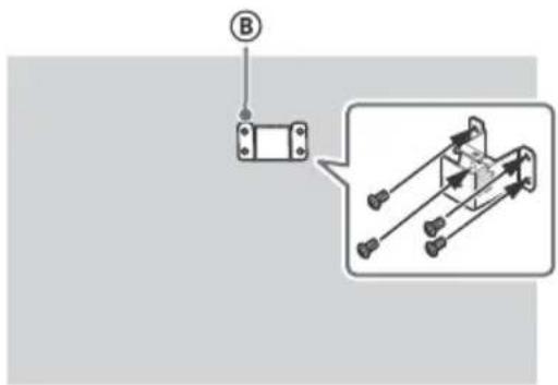
KDL-42W82xB, KDL-42W81xB, KDL-42W80xB, KDL-42/32W70xB
1

2

2


Analog: PAL, SECAM, NTSC3.58, NTSC4.43
- / - C O M P O N E N
YP_BP_R (komponent video): 1080p (50, 60 Hz),
1080i (50, 60 Hz), 720p (50, 60 Hz), 576p, 576i, 480p, 480i
Lydinngang (phonoplugger)
AV2
Over-under: 1080p (30, 50, 60 Hz), 1080/24p,
1080i (50, 60 Hz), 720p (50, 60 Hz)
Lyd: 5.1 kanal lineær PCM: 32, 44,1 og 48 kHz, 16,
Over-under: 1080p (30 Hz), 1080/24p,
1080i (50, 60 Hz), 720p (50, 60 Hz)
Lyd: 5.1 kanal lineær PCM: 32, 44,1 og 48 kHz,
16, 20 og 24 bits, Dolby Digital
DIGITAL AUDIO OUT (OPTICAL)
Digital optisk kontakt (tokanals lineær PCM, Dolby Digital)
C→ AUDIO OUT/Ω
Lydutgang (stereo miniplugg)
Hodetelefoner-kontakt
The Heights, Brooklands
Weybridge, Surrey, KT 13 0XW
United Kingdom.
natural_image
Two human figures carrying a rectangular device (no text or symbols visible)© Śruba (+PSW 4 × 10)
KDL-50W82xB,
KDL-50W81xB,
KDL-50W80xB,
KDL-50W70xB (2)
KDL-42W82xB,
KDL-42W81xB,
KDL-42W80xB,
KDL-42/32W70xB (1)

natural_image
Technical line drawing of a mechanical bracket or clamp (no text or symbols)KDL-42W82xB, KDL-42W81xB, KDL-42W80xB, KDL-42/32W70xB
natural_image
Simple line drawing of a battery with an attached top component and base labeled 'SONY' (no text or symbols beyond label)-∅/ -∅ C O M P O N E N T I
YP _B PR (wideo komponentowe): 1080p (50, 60 Hz), 1080i (50, 60 Hz), 720p (50, 60 Hz), 576p, 576i, 480p, 480i
Wideo (2D): 1080p (30 Hz), 1080/24p,
1080i (50, 60 Hz), 720p (30, 50, 60 Hz),
720/24p, 576p, 576i, 480p, 480i
Wideo (3D):
Obok siebie: 1080/24p, 1080i (50, 60 Hz), 720p (50, 60 Hz)
Nad i pod 1080p: 1080p (30 Hz), 1080/24p, 1080i (50, 60 Hz), 720p (50, 60 Hz)
DIGITAL AUDIO OUT (OPTICAL)
- Opera® Devices SDK from Opera Software ASA. Copyright 1995-2014 Opera Software ASA. All rights reserved.
- Wi-Fi, Wi-Fi Direct i Miracast to znaki towarowe lub zarejestrowane znaki towarowe Wi-Fi Alliance.
- Designed with UEITM Technology Under License from Universal Electronics Inc. Portions © UEI 2000 – 2013
natural_image
Two human silhouettes holding a rectangular device, no text or symbols visible© Šroub (+PSW 4 × 10)
KDL-50W82xB,
KDL-50W81xB,
KDL-50W80xB,
KDL-50W70xB (2)
KDL-42W82xB,
KDL-42W81xB,
KDL-42W80xB
KDL-42/32W70xB (1)

Stojan (dodaný)
H

natural_image
Technical line drawing of a mechanical bracket or clamp (no text or symbols)KDL-42W82xB, KDL-42W81xB, KDL-42W80xB, KDL-42/32W70xB

KDL-42W82xB, KDL-42W81xB, KDL-42W80xB, KDL-42/32W70xB
1

2

2

- / - C O M P O N E N
YP_BP_R (komponentní video): 1080p (50, 60 Hz),
1080i (50, 60 Hz), 720p (50, 60 Hz), 576p, 576i, 480p, 480i
Audio vstup (phono konektory)
AV2
Video (2D): 1080p (30 Hz), 1080/24p,
1080i (50, 60 Hz), 720p (30, 50, 60 Hz),
720/24p, 576p, 576i, 480p, 480i
Video (3D):
Vedle sebe: 1080/24p, 1080i (50, 60 Hz),
720p (50, 60 Hz)
Nad/pod: 1080p (30 Hz), 1080/24p,
1080i (50, 60 Hz), 720p (50, 60 Hz)
DIGITAL AUDIO OUT (OPTICAL)
- Opera® Devices SDK from Opera Software ASA. Copyright 1995-2014 Opera Software ASA. All rights reserved.
- Designed with UEI Technology™ Under License from Universal Electronics Inc. Portions © UEI 2000 – 2013
natural_image
Two human silhouettes holding a rectangular device, no text or symbols visible© Skrutka (+PSW 4 × 10)
KDL-50W82xB,
KDL-50W81xB,
KDL-50W80xB,
KDL-50W70xB (2)
KDL-42W82xB,
KDL-42W81xB,
KDL-42W80xB,
KDL-42/32W70xB (1)

Stojan (dodáva sa)
H
natural_image
Technical line drawing of a mechanical bracket or clamp (no text or symbols)KDL-42W82xB, KDL-42W81xB, KDL-42W80xB, KDL-42/32W70xB
KDL-42W82xB, KDL-42W81xB, KDL-42W80xB, KDL-42/32W70xB
KDL-42W82xB, KDL-42W81xB, KDL-42W80xB, KDL-42/32W70xB
1


2
2

natural_image
Simple line drawing of a monitor with a screen labeled 'NONY' and a small scale indicator (no text or symbols beyond the label)Video (2D): 1080p (30 Hz), 1080/24p,
1080i (50, 60 Hz), 720p (30, 50, 60 Hz),
720/24p, 576p, 576i, 480p, 480i
Video (3D):
Vedla seba: 1080/24p, 1080i (50, 60 Hz), 720p (50, 60 Hz)
Nad sebou: 1080p (30 Hz), 1080/24p,
1080i (50, 60 Hz), 720p (50, 60 Hz)
DIGITAL AUDIO OUT (OPTICAL)
natural_image
Two human silhouettes holding a rectangular device, no text or symbols visible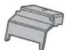
© Csavar (+PSW 4 × 10)
KDL-50W82xB, KDL-50W81xB, KDL-50W80xB, KDL-50W70xB (2) KDL-42W82xB, KDL-42W81xB, KDL-42W80xB, KDL-42/32W70xB (1)

natural_image
Technical line drawing of a mechanical bracket or clamp (no text or symbols)KDL-42W82xB, KDL-42W81xB, KDL-42W80xB, KDL-42/32W70xB
KDL-42W82xB, KDL-42W81xB, KDL-42W80xB, KDL-42/32W70xB

Analog: PAL, SECAM, NTSC3.58, NTSC4.43
DIGITAL AUDIO OUT (OPTICAL)
INFORMATIE IMPORTANTĂ 2
INFORMATIE IMPORTANTĂ
natural_image
Two human silhouettes holding a rectangular device, no text or symbols visible© Şurub (+PSW 4 × 10)
KDL-50W82xB,
KDL-50W81xB,
KDL-50W80xB,
KDL-50W70xB (2)
KDL-42W82xB,
KDL-42W81xB,
KDL-42W80xB,
KDL-42/32W70xB (1)

Suport (furnizat)
H

natural_image
Technical line drawing of a mechanical bracket or clamp (no text or symbols)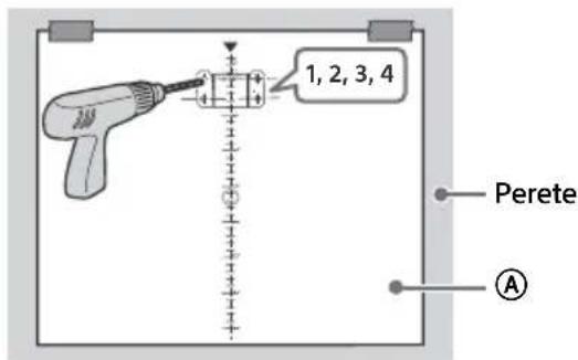
Analogic: PAL, SECAM, NTSC3.58, NTSC4.43
- / - C O M P O N E N
YP_BP_R (video pe componente): 1080p (50, 60 Hz), 1080i (50, 60 Hz), 720p (50, 60 Hz), 576p, 576i, 480p, 480i
Intrare audio (mufe fono)
AV2
Intrare video (pin fono comun cu intrarea Y)
Alăturate: 1080p (50, 60 Hz), 1080/24p,
1080i (50, 60 Hz), 720p (50, 60 Hz)
Suprapuse: 1080p (30, 50, 60 Hz), 1080/24p,
1080i (50, 60 Hz), 720p (50, 60 Hz)
Video (2D): 1080p (30 Hz), 1080/24p,
1080i (50, 60 Hz), 720p (30, 50, 60 Hz),
720/24p, 576p, 576i, 480p, 480i
Video (3D):
Alăturate: 1080/24p, 1080i (50, 60 Hz),
720p (50, 60 Hz)
Suprapuse: 1080p (30 Hz), 1080/24p,
1080i (50, 60 Hz), 720p (50, 60 Hz)
DIGITAL AUDIO OUT (OPTICAL)
natural_image
Line drawing of two human figures holding a rectangular device (no text or symbols)natural_image
Technical line drawing of a mechanical bracket or clamp (no text or symbols)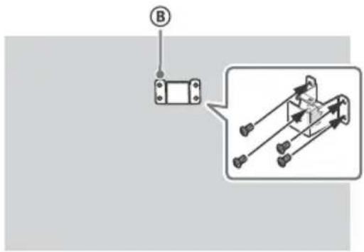
natural_image
Simple line drawing of a battery with an attached top component and base labeled 'SONY' (no text or symbols beyond label)natural_image
Line drawing of two human figures holding a rectangular device (no text or symbols)(D) Bíδα (+PSW 6 × 12) (2)

⑤ Διαχωριστικό (2)
⑤ Πλάκα κάλυψης βάσης KDL-50W82xB, KDL-50W81xB, KDL-50W80xB, KDL-50W70xB (2) KDL-42W82xB, KDL-42W81xB, KDL-42W80xB, KDL-42/32W70xB (1)
G Bíδα (+PSW 4 × 10) KDL-50W82xB, KDL-50W81xB, KDL-50W80xB, KDL-50W70xB (2) KDL-42W82xB, KDL-42W81xB, KDL-42W80xB, KDL-42/32W70xB (1)

Βάση (παρέχεται)
H
natural_image
Technical line drawing of a mechanical clamp or bracket (no text or symbols)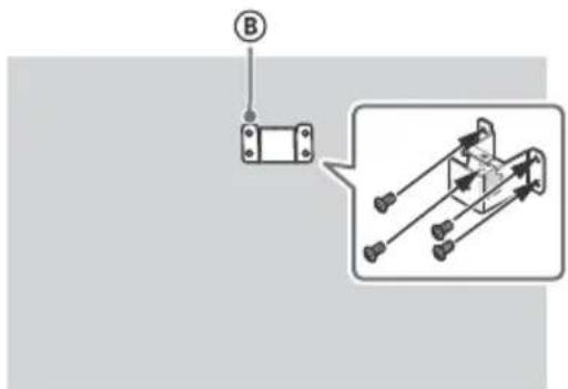
natural_image
Line drawing of two human figures carrying a rectangular device (no text or symbols)© Vida (+PSW 4 × 10)
KDL-50W82xB,
KDL-50W81xB,
KDL-50W80xB,
KDL-50W70xB (2)
KDL-42W82xB,
KDL-42W81xB,
KDL-42W80xB
KDL-42/32W70xB (1)

natural_image
Technical line drawing of a mechanical bracket or support structure (no text or symbols)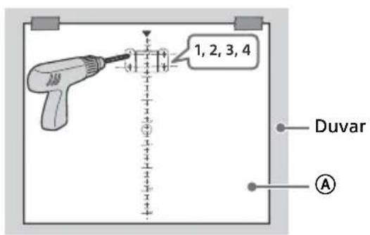
flowchart
graph TD
    A["Internal Cable Component"] --> B["Pin"]
    B --> C["Internal Cable Assembly"]
    C --> D["Final Cable Assembly"]
→ C O M P O N E N T I
YP _B PR (Component Video): 1080p (50, 60 Hz), 1080i (50, 60 Hz), 720p (50, 60 Hz), 576p, 576i, 480p, 480i
natural_image
Two human silhouettes carrying a rectangular device, no text or symbols visiblenatural_image
Technical line drawing of a mechanical bracket or support structure (no text or symbols)KDL-42W82xB, KDL-42W81xB, KDL-42W80xB, KDL-42/32W70xB

DIGITAL AUDIO OUT (OPTICAL)
natural_image
Line drawing of two human figures carrying a rectangular object (no text or symbols)natural_image
Technical line drawing of a mechanical bracket or clamp (no text or symbols)KDL-42W82xB, KDL-42W81xB, KDL-42W80xB, KDL-42/32W70xB
KDL-42W82xB, KDL-42W81xB, KDL-42W80xB, KDL-42/32W70xB
1


2

2
- / - C O M P O N E N T I
DIGITAL AUDIO OUT (OPTICAL)
Mobile High-Definition Link

Bluetooth®

gracenote.
dts®
Digital Surround

For useful information about Sony products
- Introduction
- Note
- Location of the identification label
- WARNING
- NOTICE FOR CUSTOMERS IN THE UNITED KINGDOM
- How to replace the fuse
- IMPORTANT NOTICE
- Notice for Wireless Signal
- Safety information
- Installation/Set-up
- Installation
- Transporting
- Topple prevention
- Ventilation
- Installed on the wall
- Installed with stand
- Mains lead
- NOTE ON MAINS ADAPTOR
- Prohibited Usage
- Location:
- Environment:
- Situation:
- Broken pieces:
- When not in use
- For children
- If the following problems occur...
- When:
- About LCD Monitor Temperature
- WALL-MOUNT BRACKET
- To Customers:
- To Sony Dealers and Contractors:
- Precautions
- Viewing the TV
- LCD Screen
- Handling and cleaning the screen surface/cabinet of the TV set
- Optional Equipment
- Recommendation of F-type plug
- Caution about handling the remote control
- Wireless Function of the unit
- Disposal of the TV set
- Disposal of Old Electrical & Electronic Equipment (Applicable in the European Union and other European countries with separate collection systems)
- Disposal of waste batteries (applicable in the European Union and other European countries with separate collection systems)
- Installing the TV to the Wall
- To Customers
- To Sony Dealers and Contractors
- Installing the Brackets on the wall
- Prepare necessary items.
- Stand (supplied)
- Screws for Wall-Mount Base (8 mm in diameter, not supplied)
- Installing the TV on the wall
- Dimensions of the hole positions on the wall
- Troubleshooting
- Troubles and Solutions
- Specifications
- System
- Input/Output jacks
- Others
- Power and others
- Dimensions (Approx.) (w × h × d)
- Notes on Digital TV function
- Trademark information
- Table des matières
- Cabo de alimentação
- Dimensioni (Approssimative) (I × a × p)
- Dimension (Cirka) (b × h × d)
- Vikt (Cirka)
- PRODUKTET SKAL HOLDES VÄEK FRA
- INFORMATIE IMPORTANTĂ
- Suport (furnizat)
- Βάση (παρέχεται)
Brand : SONY
Model : KDL50W828BBAE2
Category : TV