
FWD-42LX1 - Television SONY - Free user manual and instructions
Find the device manual for free FWD-42LX1 SONY in PDF.

| Product Type | LCD Television |
| Brand | Sony |
| Model | FWD-42LX1 |
| Screen Size | 42 inches (diagonal 1068 mm) |
| Display Resolution | 1366 x 768 pixels |
| Display Technology | a-Si TFT Active Matrix LCD Screen |
| Pixel Pitch | 0.681 mm (horizontal) x 0.681 mm (vertical) |
| Image Size | 930 mm (horizontal) x 523 mm (vertical) |
| Preset Video Signal | Computer (VGA, SVGA, XGA, etc.) and SDTV/HDTV (PAL, NTSC, 1080i, 720p, etc.) |
| Shift Clock | 13.5 MHz to 140 MHz |
| Video Inputs | INPUT1 (Digital DVI), INPUT2 (Analog RGB/Component), OPTION1 (VIDEO/COM), OPTION2 (VIDEO) |
| Audio Inputs | INPUT1 (Stereo mini jack), INPUT2 (Stereo mini jack), OPTION (depending on adapter) |
| Outputs | AUDIO OUT (Pin jack), Speakers (SPEAKER terminal), REMOTE RS-232C, CONTROL S IN/OUT |
| Audio Power | 7 W + 7 W (6 ohms) |
| Power Supply | 100-240 V AC, 50/60 Hz, 2.8 A to 1.1 A |
| Power Consumption | Not specified (max approx. 280 W) |
| Operating Conditions | Temperature: 0 °C to +35 °C, humidity: 20 to 90 % (without condensation) |
| Main Functions | Multiple display (2x2 to 4x4), Picture and Picture (PAP), Picture in Picture (PinP), anti-theft lock, on/off timer, energy saving, image mode (Vivid, Standard, User 1-3) |
| Supplied Accessories | Mains power cord, plug holder (2), cable holder (6), remote control RM-980, AAA (R03) batteries (2), instructions manual |
| Maintenance and Cleaning | Disconnect before cleaning; use a soft, dry cloth for the screen and casing; do not use alcohol, benzine, or thinner |
| Safety | Fire or electric shock risk: do not expose to rain or moisture; do not open the chassis; refer servicing to qualified personnel |
Frequently Asked Questions - FWD-42LX1 SONY
User questions about FWD-42LX1 SONY
0 question about this device. Answer the ones you know or ask your own.
Ask a new question about this device
Download the instructions for your Television in PDF format for free! Find your manual FWD-42LX1 - SONY and take your electronic device back in hand. On this page are published all the documents necessary for the use of your device. FWD-42LX1 by SONY.
USER MANUAL FWD-42LX1 SONY
FWD-42LX1/32LX1/42LX1E/32LX1E
安全のために
侧面
natural_image
Diagram of a vertical panel with internal components and a numbered label (6), no readable text or symbols present.①インジケーター部
BKM-FW10 / BKM-FW11 / BKM-FW12
natural_image
Technical line drawing of a mechanical component with dimension label '5' and hatched fill (no text or symbols beyond basic geometry)单位:cm
ご注意
natural_image
Diagram of a mechanical device with a tool and wire, no text or symbols presentご注意
SPEAKER 7 W+ 7 W (6Ω)
適合負荷インピーダンス6~16 Ω
$$ \mathrm{FWD-32LX1:170W} $$
動作条件 温度:0~+35℃
$$ \text {湿度}: 20 \sim 90 \% (\text {結露のないこと}) $$
The model and serial numbers are located on the rear. Record the model and serial numbers in the spaces provided below. Refer to these numbers whenever you call upon your Sony dealer regarding this product.
Model No. ____ Serial No. ____
To prevent fire or shock hazard, do not expose the unit to rain or moisture.
To avoid electrical shock, do not open the cabinet. Refer servicing to qualified personnel only.
On transportation
When you carry the display unit, hold the unit itself, not the speakers. If you fail to do so, the speakers may come out of the unit and the unit may fall. This can cause injury.
For customers in the U.S.A.
If you have any questions about this product, you may call; Sony Customer Information Services Center 1-800-222-7669 or http://www.sony.com/
Declaration of Conformity
Trade Name: SONY
Model: FWD-42LX1/42LX1E/32LX1/
32LX1E
Responsible Party: Sony Electronics Inc.
Address: 16530 Via Esprillo, San Diego, CA
92127 U.S.A.
Telephone Number: 858-942-2230
This device complies with Part 15 of the FCC Rules. Operation is subject to the following two conditions: (1) This device may not cause harmful interference, and (2) this device must accept any interference received, including interference that may cause undesired operation.
This equipment has been tested and found to comply with the limits for a Class B digital device, pursuant to Part 15 of the FCC Rules. These limits are designed to provide reasonable protection against harmful interference in a residential installation. This equipment generates, uses, and can radiate radio frequency energy and, if not installed and used in accordance with the instructions, may cause harmful interference to radio communications. However, there is no guarantee that interference will not occur in a particular installation. If this equipment does cause harmful interference to radio or television reception, which can be determined by turning the equipment off and on, the user is encouraged to try to correct the interference by one or more of the following measures:
- Reorient or relocate the receiving antenna.
- Increase the separation between the equipment and receiver.
- Connect the equipment into an outlet on a circuit different from that to which the receiver is connected.
- Consult the dealer or an experienced radio/TV technician for help.
You are cautioned that any changes or modifications not expressly approved in this manual could void your authority to operate this equipment.
For customers in Canada
This class B digital apparatus complies with Canadian ICES-003.
The socket-outlet should be installed near the equipment and be easily accessible.
CAUTION
RISK OF EXPLOSION IF BATTERY IS REPLACED BY AN INCORRECT TYPE. DISPOSE OF USED BATTERIES ACCORDING TO THE LOCAL RULES.
Table of Contents
Precautions 5 (GB)
Location and Function of Parts and Controls ..... 7 (GB)
Front / Rear / Side 7 (GB)
Indicator Section 8 (GB)
Control Button Section (Top) 8 (GB)
Connector Panel 9 (GB)
Remote Commander RM-980 11 (GB)
Caution 13 (GB)
Connections 14 (GB)
Connecting the Speakers 14 (GB)
Connecting the AC Power Cord 14 (GB)
Attaching the ferrite cores.... 14 (GB)
Cable management 15 (GB)
Using On-screen Menus 16 (GB)
Operating Through Menus 16 (GB)
Menu Guide 16 (GB)
Watching the Picture 21 (GB)
Switching the Input Signal 21 (GB)
Input Signal, Picture Mode and Display Status Information 22 (GB)
Selecting Image Quality 24 (GB)
Adjusting the Picture 24 (GB)
Adjusting the Contrast, Brightness, Chroma, and Phase, etc. 24 (GB)
Restoring the Adjust Picture Menu Items to Their Original Settings 27 (GB)
Picture Enlargement 28 (GB)
Setting Auto Wide 28 (GB)
Setting the Aspect 29 (GB)
Resizing and Positioning the Picture 30 (GB)
Adjusting the Size, Position, or the Pixels of the Picture 30 (GB)
Viewing two pictures at the same time 32 (GB)
Activating a picture or swapping the positions of two pictures .... 32 (GB)
Zooming in on a picture 33 (GB)
Adjusting the position of the inset picture (For PinP only) 33 (GB)
Setting up the Multi Display 34 (GB)
Adjusting the Sound Quality 35 (GB)
Adjusting the Treble, Bass, and Balance, etc. ..... 35 (GB)
Restoring the Adjust Sound Menu Items to Their Original Settings 35 (GB)
Selecting the On-screen Language 36 (GB)
Adjusting Color Matrix 36 (GB)
Controlling Power On/Off Automatically (Timer Function).... 37 (GB)
Adjusting the time and the day 37 (GB)
Displaying the time 37 (GB)
On/Off Timer Function 38 (GB)
Setting the Security Lock 38 (GB)
To activate the Security Lock 38 (GB)
Security authentication 39 (GB)
To deactivate the Security Lock 39 (GB)
Self-diagnosis Function 39 (GB)
Operating a Specific Display With the Remote Commander 40 (GB)
Specifications 41 (GB)
Precautions
On safety
- A nameplate indicating operating voltage, power consumption, etc. is located on the rear of the unit.
- Should any solid object or liquid fall into the cabinet, unplug the unit and have it checked by qualified personnel before operating it any further.
- Unplug the unit from the wall outlet if it is not to be used for several days or more.
- To disconnect the AC power cord, pull it out by grasping the plug. Never pull the cord itself.
- When you install the unit on the floor, be sure to use the optional stand.
On installation
- A low adequate air circulation to prevent internal heat build-up. Do not place the unit on surfaces (rugs, blankets, etc.) or near materials (curtains, draperies) that may block the ventilation holes.
- Do not install the unit in a location near heat sources such as radiators or air ducts, or in a place subject to direct sunlight, excessive dust, mechanical vibration or shock.
- When you install multiple equipment with the unit, the following problems, such as malfunction of the Remote Commander, noisy picture, noisy sound, may occur depending on the position of the unit and other equipment.
On the LCD panel
- You may see some bright spots of red, blue or green, or dark spots appearing on the screen. These do not indicate a malfunction. Although the LCD panel is manufactured with extremely high precision technology, it can generate a few dark or bright pixels.
- Keeping the LCD panel facing toward the sun for a long time will damage the panel. Take this into account when you install the unit outdoor or by a window.
- Do not push, scratch or put a heavy weight on the panel. These can cause irregularities in the screen or a malfunction of the LCD panel.
-
You may find the screen looks darker or an afterimage occurs when using the unit in a colder environment. These do not indicate a malfunction. The screen will return to normal operation as the temperature rises.
-
If you display a still image for a long time, ghosting may occur. This will disappear as time passes.
- The panel surface or the cabinet may warm up during use. This does not indicate a malfunction.
On cleaning the display
The panel surface
- Be sure to unplug the power cord before cleaning the display.
- The LCD panel surface has been given a special finish. Avoid touching the LCD screen. When cleaning the panel face, wipe off stains using a dry, soft cloth.
- N ever use rubbing alcohol, benzine or thinner for cleaning. They may damage the finish of the panel face.
- When using a chemically treated cloth for cleaning, follow the directions.
- Spraying the unit with volatile solvents (such as an insecticide,) or allowing the unit come into prolonged contact with rubber or plastic products may remove the coating or spoil the unit.
The cabinet
- Gently wipe off stains using a dry, soft cloth. Wipe off grimy stains using a cloth slightly moistened with a mild detergent, then wipe the area again using a dry, soft cloth.
- Never use rubbing alcohol, benzine or thinner for cleaning. They may damage the finish of the cabinet or can remove the markings on it.
Notes on handling and cleaning the display panel
The display panel's special surface finish should be treated with care when cleaning or handling the TV. When cleaning it, use a soft cleaning cloth to avoid touching the panel directly.
On repacking
Do not throw away the carton and packing materials. They make an ideal container in which to transport the unit. When shipping the unit, repack it as illustrated on the carton.
If you have any questions on this unit, contact your authorized Sony dealers.
Warning on power connection
Use the proper power cord for your local power supply.
| United States, Continental United KingdomCanada Europe Australia, New Zealand | dom, Ireland, Japan | ||||
| Plug type VM0233 COX-07 | 636 — | a) | VM1296 | ||
| Female end VM0089 COX- | 02 VM0310B VM030 | 3B VM13 | 13 | ||
| Cord type SVT H05VV-F | CEE (13) 53rd (O.C) HVCTF | ||||
| Minimum cord set rating 10 | A/125V | 10A/250V | 10 | A/250V 10A/125V | |
| Safety approval UL/CSA VDE | VDE | DENAN-HO | |||
a) Note: Use an appropriate rating plug which complies with local regulations.
For Customers in the United States
This product contains mercury. Disposal of this product may be regulated if sold in the United States.
For disposal or recycling information, please contact your local authorities or the Electronics Industries
Alliance (http://www.eiae.org).
Location and Function of Parts and Controls
Front / Rear / Side
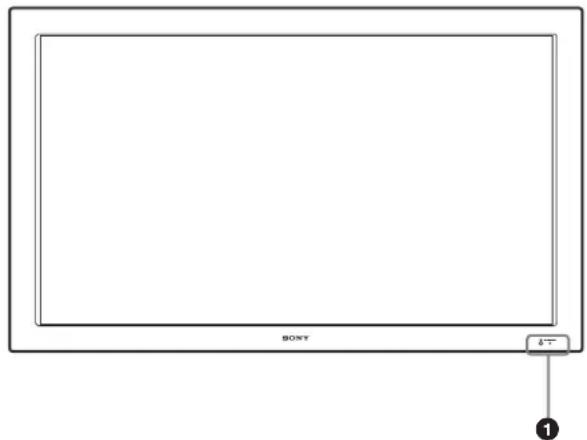
Front
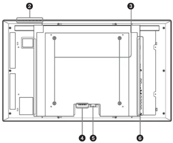
Rear
Side
natural_image
Diagram of a vertical panel with labeled pins and connection points, no text or symbols present① Indicator section
For details on the Indicator section, see “Indicator Section” on page 8 (GB).
② Control button section
For details on the control button section, see “Control Button Section (Top)” on page 8 (GB).
③ Stand installation hooks
Use these hooks to install the stand (not supplied).
④ SPEAKER Socket
Connects the speakers (not supplied) to this socket to output the audio matching the signal displayed on the screen.
⑤ ∼ AC IN socket
Connect the supplied AC power cord to this socket and to a wall outlet. Once you connect the AC power cord, the POWER/STANDBY indicator lights up in red and the display goes into the standby mode.
For more details on the power cord, see “Connecting the AC Power Cord” on page 14 (GB).
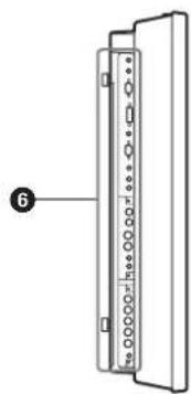
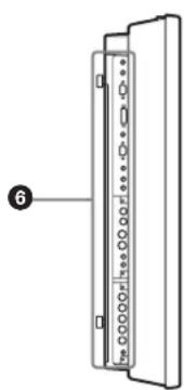
6 Connector panel
For details on the connector panel, see “Connector Panel” on page 9 (GB).
Indicator Section
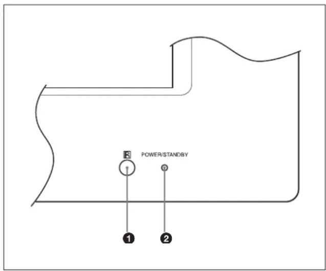
① Remote control detector
Receives the signals from the Remote Commander.
② POWER/STANDBY indicator
Lights up in green when the display unit is powered on. Lights up in red in the standby mode. Lights up in orange when the display enters the power saving mode while a signal is input from a computer.
When the input signal is switched, the indicator blinks green.
When the POWER/STANDBY indicator blinks red, see "Self-diagnosis Function" on page 39 (GB).
Control Button Section (Top)
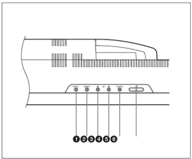
① INPUT button
Press to select a signal to be input from the INPUT or OPTION connector.
The signal to be input switches as follows each time you press the INPUT button.
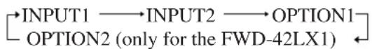
When an option adaptor is not installed in the OPTION slot, OPTION1 or OPTION2 will be skipped.
② MENU button
Press to show menus. Press again to hide them.
③ ④ ↓/↑ (cursor/volume) button
Press to move the cursor (yellow), set a value, or control speaker volume.
⑤ ENTER button
Press to set your choice.
6 POWER switch
Press to power on the display unit. Press again to return to the standby mode.
Note
To protect the panel, a certain amount of time is required to turn the unit ON/STANDBY. Wait about 5 seconds after one of these operations before pressing this switch again.
Connector Panel
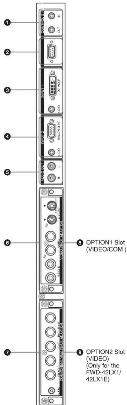
① CONTROL S IN/OUT (Control S Signal Input/Output) Connector (Minijack)
You can control multiple devices with a single remote commander when connected to the CONTROL S connector of a video device or other display. Connect the CONTROL S OUT connector on this display to the CONTROL S IN connector of the other device, and connect the CONTROL S IN connector on this display to the CONTROL S OUT connector of the other device.
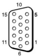
② REMOTE (RS-232C) connector (D-sub 9-pin) This connector allows remote control of the display using the RS-232C protocol. For details, contact your authorized Sony dealers.
③ INPUT1 (DIGITAL RGB IN) connectors
DVI : Connects to the digital RGB signal output of video devices. Supports HDCP copy protection. AUDIO (Stereo minijack) : Inputs an audio signal. Connects to the audio output of video devices.
④ INPUT2 (ANALOG RGB/COMPONENT IN) connectors
RGB/COMPONENT (D-sub 15-pin) : Connects to the analog RGB signal or component (YUV) signal output of a piece of video equipment.
AUDIO (Stereo minijack) : Inputs an audio signal. Connects to the audio output of a piece of video equipment.
⑤ AUDIO OUT L/R (Pinjack)
Outputs an audio of the signal currently indicated on the screen. Outputs an audio signal corresponding to the Active Picture while in the P&P or PinP mode.
⑥ VIDEO connectors (A BKM-FW10 is preinstalled only in the FWD-42LX1/32LX1.)
S VIDEO IN (Mini DIN 4-pin) : Connects to the Y/C signal output of a piece of video equipment. S VIDEO OUT (Mini DIN 4-pin) : Connects to the Y/C signal input of a piece of video equipment.
VIDEO IN (BNC) : Connects to the video signal output of a piece of video equipment.
VIDEO OUT (BNC) : Connects to the video signal input of a piece of video equipment.
AUDIO IN L/R (Pinjack) : Inputs an audio signal. Connects to the audio output of a piece of video equipment.
⑦ COMPONENT/RGB IN (A BKM-FW11 is preinstalled only in the FWD-42LX1.)
Y/G P_B/C_B/B P_R/C_R/R IN (BNC): Connects to the analog RGB signal or component (YUV) signal output of a piece of video equipment or a computer.
HD VD IN : Connects to the synchronization signal output of a computer.
AUDIO (Stereo minijack) : Inputs an audio signal.
Connects to the audio output of a piece of video equipment or a computer.
⑧ OPTION1 slot (VIDEO/COM port)
This slot supports video signals and communication function.
⑨ OPTION2 slot (VIDEO port)
(Only for the FWD-42LX1/42LX1E)
This slot supports video signals. The optional adaptor with communication function should be installed in
⑧ OPTION1 slot.
Optional adaptors (Not supplied)
The connectors marked with 6 and 7 on the connector panel are slot-in types and can be fitted with any of the optional adaptors in the display; BKM-FW10, BKM-FW11 or BKM-FW12.
(A BKM-FW10 is the same as the connectors 6, and a BKM-FW11 is the same as the connectors 7.) The OPTION2 slot is equipped only on the FWD-42LX1/42LX1E.
For details on installation, consult your Sony dealers.
RGB/COMPONENT ACTIVE THROUGH ADAPTOR BKM-FW12 (Not supplied)
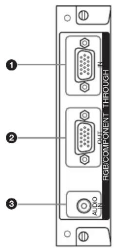
① RGB/COMPONENT IN (D-sub 15-pin) :
Connects to the component signal output or analog RGB signal output of a piece of video equipment or a computer.
② RGB/COMPONENT OUT (D-sub 15-pin) :
Connects to the component signal input or analog RGB signal input of a piece of video equipment or a computer.
③ AUDIO IN (Stereo minijack) :
Inputs audio signal. Connects to the audio signal output of a piece of video equipment or a computer. For details on inputting a component signal to the connector, see “Pin assignment” on page 42 (GB).
Note
When the unit is not connected to an AC power or is in the standby mode, no signal is output from the RGB/COMPONENT OUT.
Remote Commander RM-980
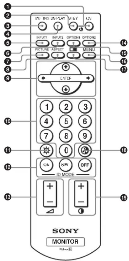
① POWER ON switch
Press to power on the display.
② STANDBY button
Press to change the display to the standby mode.
③ MUTING button
Press to mute the sound. Press again to restore sound.
④ DISPLAY button
Press to display the input signal information and the picture mode on the screen. Press again to hide them. If this displayed information is left undisturbed for a short time, it will disappear automatically.
⑤ INPUT1 button
Press to select the signal input to the INPUT1 connectors.
⑥ INPUT2 button
Press to select the signal input to the INPUT2 connectors. Each press toggles between RGB and COMPONENT.
⑦ PICTURE button
Selects Picture mode. Each press toggles between Vivid, Standard, and User 1 to 3.
⑧ ASPECT button
Press to change the aspect ratio (Wide Mode).
⑨ ↑/↓/←/→/ENTER buttons
The ↑/↓/←/→ buttons move the menu cursor (yellow) and set values, etc. Pressing the ENTER button sets the selected menu or setting items.
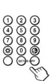
10 Number buttons
Press to enter index numbers.
⑪ BRIGHTNESS button
Adjusts the brightness when Picture Mode is set to any of “User1” to “User3.” Press this button, then adjust the brightness with ↑/↓ or ←/→ buttons ⑨.
⑫ ID MODE (ON/SET/OFF) buttons
Press ON to show an index number on the screen. Enter the index number of the display you want to operate with Number buttons 10, then press SET. Press OFF to return to the normal mode.
For details on the index numbers, see “Operating a Specific Display With the Remote Commander” on page 40 (GB).
⑬ VOLUME +/- button
Press to adjust the volume.
14 OPTION2 button
Selects the signal input to an optional adaptor (except BKM-V10) when you install one in the unit. Each time you press this button, the signal input to the OPTION2 switches.
Note
You cannot operate this button for the FWD-32LX1/32LX1E that does not have the OPTION2 slot.
15 OPTION1 button
When an option board is installed, selects a signal to be input from the device connected to the option board. Each time you press this button, the signal input to the OPTION1 switches.
16 MENU button
Press to show menus. Press again to hide them.
17 □ button
Selects the PICTURE AND PICTURE (PAP) mode. Each press toggles between PAP off, P&P, and PinP.
Location and Function of Parts and Controls
18 CHROMA button
Adjusts the chroma when the picture mode is set to any of "User1" to "User3." Press this button and adjust the chroma with the ↑/↓ or ←/→ buttons ⑨.
19 CONTRAST +/- button
Adjusts the contrast when Picture Mode is set to any of "User1" to "User3."
Installing batteries
Insert two size AAA (R03) batteries in correct polarity.
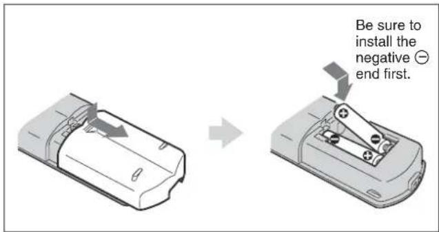
- In normal operation, batteries will last up to half a year. If the Remote Commander does not operate properly, the batteries might be exhausted sooner. Replace them with new ones.
- To avoid damage from possible battery leakage, remove the batteries if you do not plan to use the Remote Commander for a fairly long time.
When the Remote Commander does not work
Check that the POWER/STANDBY indicator lights up and the Control Mode in the Remote menu is not set to "Display Unit Only." The Remote Commander operates the display only when both of the two conditions below are met.
• The display is turned on, or it is in the standby mode.
- The Control Mode in the Remote menu is set to "Display + Remote" or "Remote Only."
For details on the Control Mode, see "Control Mode" on page 19 (GB).
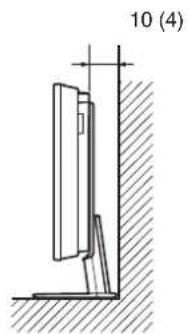
Caution
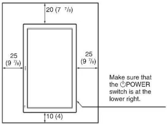
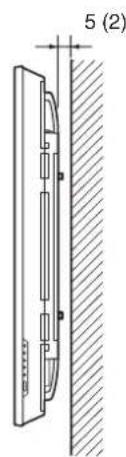
Provide an ample amount of space around the display
- When you use the display, make sure there is more space around the display than that shown in the figure below. This will allow for proper ventilation.
- The ambient temperature must be 0 °C to +35 °C (32 °F to 95 °F).
- When installing the display horizontally, use the display stand SU-42FW/32FW (not supplied) as a stand.
- Regarding the installation of hardware such as brackets, screws, or bolts, we cannot specify the products. Actual installation is up to the authorized local dealers. Consult with qualified Sony personnel for installation.
- While the unit is on, a certain amount of heat builds up inside. This can cause burns. Avoid touching the top or rear of the unit when it is powered on or just after it has entered standby mode.
When using the stand (not supplied)
Front
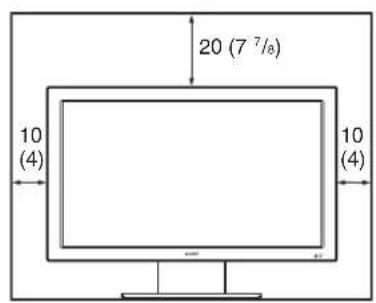
Side
Units: cm (inches)
When mounting the display horizontally Front ____
Side
Units: cm (inches)
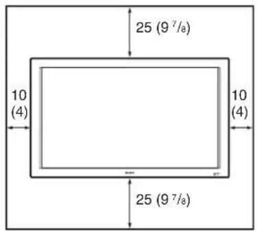
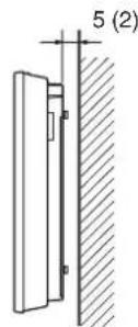
When mounting the display vertically
Front ____
Side
Units: cm (inches)
Note
When mounting the display vertically, you cannot use the speakers SS-SP42FW/32FW (not supplied).
Connections
Before you start
- First make sure that the power to each piece of equipment is turned off.
- U se connecting cables suitable for the equipment to be connected.
- The cable connectors should be fully inserted into the jacks. A loose connection may cause hum and other noise.
• To disconnect the cable, pull it out by grasping the plug. Never pull the cable itself. - Refer to the instruction manual of the equipment to be connected.
- Insert the plug securely into the AC IN socket.
- Use one of the two AC plug holders (supplied) that will securely hold the AC plug.
Connecting the Speakers
You can enjoy viewing with a greater sense of presence by connecting speakers SS-SP42FW/32FW (not supplied). Please be sure to connect the speakers correctly. For more details on connecting the speakers, see the operating manual that came with the speakers.
For details on how to route the speaker cords, refer to "Using the cable holders" on page 15 (GB).
Connecting the AC Power Cord
1 Plug the AC power cord into the AC IN socket. Then, attach the AC plug holder (supplied) to the AC power cord.
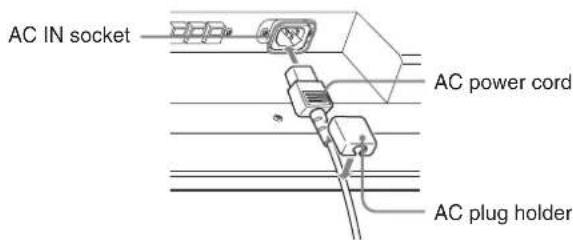
2 Slide the AC plug holder over the cord until it connects to the AC IN socket cover.
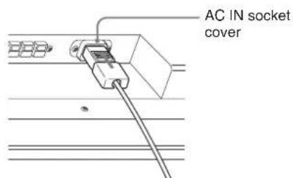
To remove the AC power cord
After squeezing the AC plug holder and freeing it, grasp the plug and pull out the AC power cord.
Attaching the ferrite cores
1 Attach the ferrite cores to the ends of the cable, closing it until it clicks.
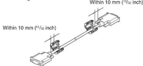
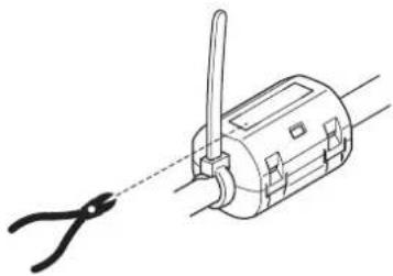
2 Wind the stopper around the cable so that the ferrite core does not slide.
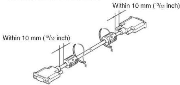
3 Tighten the stopper and cut the surplus.
natural_image
Line drawing of a mechanical device with a pair of pliers attached to its shaft (no text or symbols)Notes
- When you connect a cable to any of the terminals listed below, attach the ferrite cores provided before using the cable.
DVI-HDCP(INPUT1): Attach the ferrite cores to both ends of the cable as shown in the illustrations. - You are cautioned that this unit will not be in compliance with the EMC limits unless you attach the ferrite cores on the interconnecting cable.
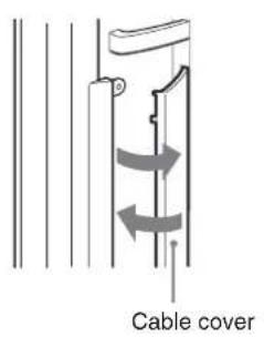
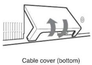
Cable management
The display has the cable covers on its back. Before connecting the cables to the display, pull the cable covers to open. After connecting the cables to the display, close the cable covers.
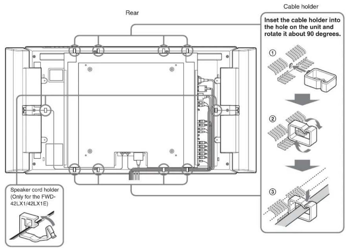
Using the cable holders
You can neatly bundle the cables with the cable holders ( ×6 ) provided. Select six out of eight holes for the cable holders. Attach the cable holders as shown in the illustration below.
When you connect the speakers SS-SP42FW (not supplied), route the speaker cords through the speaker cord holders on the rear of the display unit. (Only for the FWD-42LX1/42LX1E)
Using On-screen Menus
Operating Through Menus
Menu operating buttons
Use the buttons on the display unit or the Remote Commander for menu operations.
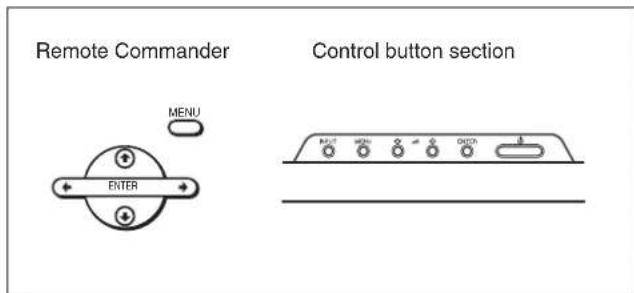
Operation of the unit is explained in these operating instructions for the case of operation using the Remote Commander. The ↑/↓ and ENTER buttons on the Remote Commander have the same functions as the ↑/↓ and ENTER buttons on the display.
Note
Operation may differ in some cases since there is no / button on the display.
Configuration of the menu
To select the language of the menus, see "Selecting the On-screen Language" on page 36 (GB).
1 Press MENU.
The main menu appears on the screen.
2 Press ↑/↓ to move the cursor (yellow) to the main menu items you want to select and press ENTER. The cursor moves to the next menu.
3 Press ↑/↓ to move the cursor (yellow) to the item you want to select and press ENTER. The menu for the selected item appears. Select an different item by repeating this procedure.
4 Press ↑/↓ to adjust or select the setting and press ENTER to set it. The setting is registered and the menu returns to the previous menu.
To complete the configuration and return to the normal screen, press MENU. To return to the previous menu level, press ↑/↓ to move the cursor to ↩ and press ENTER or ←.
Menu Guide
Note
Items that cannot be set or adjusted (depending on the setting or the type of signal input) show in dark gray.
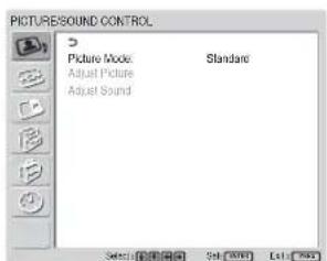
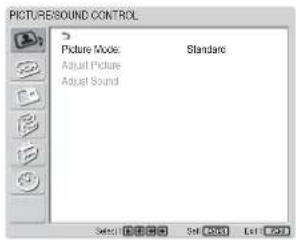
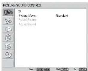
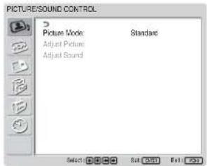
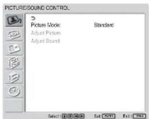
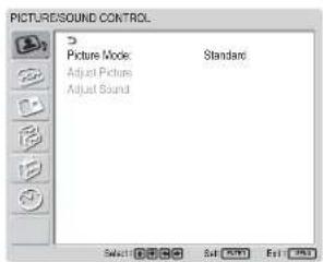
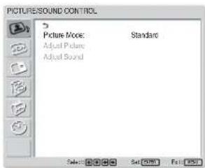
PICTURE/SOUND CONTROL menu
Adjusts the quality of sound and picture.
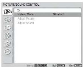
Picture Mode
Sets the image quality suitable for the type of picture or the brightness of the location where the unit is installed. For details, see "Selecting Image Quality" on page 24 (GB).
Adjust Picture
You can make fine adjustment of the picture. Set Picture Mode to any of "User1" to "User3" first.
Note
You cannot adjust the following items when Picture Mode is set to "Vivid" or "Standard." For details, see "Adjusting the Picture" on page 24 (GB).
Adjust Sound
You can make fine adjustment of the sound.
Set Picture Mode to any of "User1" to "User3" first.
Note
You cannot adjust the following items when Picture Mode is set to “Vivid” or “Standard.”
For details, see "Adjusting the Sound Quality" on page 35 (GB).

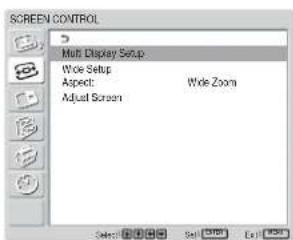
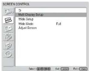
SCREEN CONTROL menu
You can resize or adjust the position of a picture.
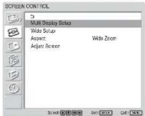
Multi Display Setup
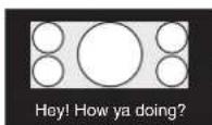
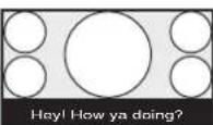
You can make settings for connecting multiple display units and forming a video wall in a 2 × 2 , 3 × 3 or 4 × 4 arrangement.
For details, see "Setting up the Multi Display" on page 34 (GB).
Wide Setup
Sets the Auto Wide function. The Auto Wide function is a function which chooses from among ordinary television broadcasts, or wide screen images, all having different proportions for horizontal and vertical display, and automatically expands the picture to a wide screen image with a 16:9 aspect ratio, enabling the most appropriate display of different types of images.
For details, see "Setting Auto Wide" on page 28 (GB).
Aspect
Switches the wide screen display to match the size and type of the picture.
For details, see "Setting the Aspect" on page 29 (GB).
Adjust Screen
This menu is used for resizing or repositioning the picture. You can also adjust the number of picture pixels using this menu.
For details, see "Resizing and Positioning the Picture" on page 30 (GB).

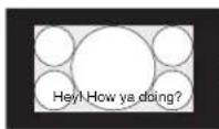
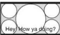
PICTURE AND PICTURE (PAP)
You can show two pictures from different signal sources, such as a computer and a video, side by side.
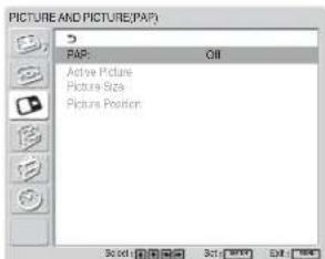
For details, see "Viewing two pictures at the same time" on page 32 (GB).

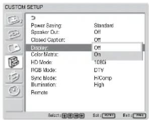
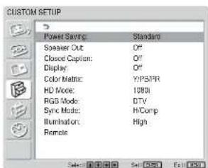
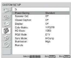
CUSTOM SETUP menu
You can reduce power consumption or set various kinds of modes.
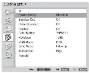
Power Saving
Reduces power consumption while showing pictures.
Standard: No energy saving
Reduce: Save energy
When you select “Reduce,” the brightness of the picture is reduced so that you can enjoy viewing pictures while reducing power consumption.
Notes
- “Power Saving: Reduce” will be resumed when you power on the unit again.
- Even when Power Saving is set to “Reduce”, you can still adjust the quality of the picture. However, note that you may lose the energy saving effects if you increase Contrast or Brightness.
Speaker Out
Set it to ON to cause sound to be emitted from the speakers SS-SP42FW/32FW (not supplied.)
Closed Caption
Displays closed captions.
While using the combination of Component + Component, you can display closed captions only for input signals from the BKM-FW11 or BKM-FW12.
Off: The caption is not displayed.
CC1-4: Displays the caption superimposed on the picture.
Display
Select On to display the input signal information and Picture Mode for about five seconds on the screen when you turn on the unit or switch the input signal.
Color Matrix
Sets the Color Matrix to show pictures in natural color tones when a component signal is input.
For details, see “Adjusting Color Matrix” on page 36 (GB).
HD Mode
Selects a mode according to an HD analog component signal input to the display unit.
1080i: When a 1080i signal is input
1035i: When a 1035i signal is input
RGB Mode
Sets the mode when a device that outputs RGB signals is connected to the display unit.
DTV: When connected to an RGB signal digital tuner, etc.
PC: When connected to a PC.
Sync Mode
Sets the mode according to the signal input at pin 13 of the RGB/COMPONENT connector. Signals can be set only to 575/50I or 480/60I.
H/Comp: When a horizontal signal or a composite synchronous signal* is input
Video: When a video signal is input
*Depending on the level of the composite synchronous signal, the image may not be displayed correctly. In that case, change the Sync Mode setting.
Input signal and Synchronous mode settings
| PIN S | signal input over the D-sub | Synchronous mode setting |
| 13 | 480/60I, 575/50I Composite Video | Video signal |
| Composite Sync | Synchronizing signal | |
| 13/14 | H Sync/V Sync | |
| 2 Sync On Green | ||
See “Pin assignment” on page 42 (GB) for more information on the pin assignments of RGB/COMPONENT connector.
Notes
- There are some inputs for which only synchronizing signals can be selected. In this case, an image will not be displayed even if a video signal is input to the 13 pin connector. Input horizontal/vertical synchronization signals through the 13 or 14 pin connectors, or input Sync On Green signals through the RGB connector.
- With Sync On Green, if the unit is not set to accept synchronizing signals, the image will not be displayed.
- Signals of the synchronous mode can be supported only with INPUT2.
- Sync Mode settings cannot be carried out for the input through the option boards.
- This unit does not support the three value sync format of composite sync and 576/60P.
Illumination
Switches the brightness of the “SONY” logo on the front of the display unit.
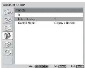
Remote
This menu is used for remote control settings.
Index Number
Sets the index number of the display.
Note
When you set the index number, use the buttons on the display unit. The index number cannot be set with the Remote Commander.
For details on the Index Number, see "Operating a Specific Display With the Remote Commander" on page 40 (GB).
Control Mode
Selects the function of the Remote Commander.
Display + Remote: Activates a remote commander supplied with the display.
Display Unit Only: Disables the remote control function. You can only make settings for the display using the control buttons on the display unit.
Remote Only: Disables the controls on the display unit when you want to control it using the Remote Commander only. You can only make settings for the display using the Remote Commander.
Note
When operating this item, the modes you can select differ depending on the key you are using.
When using ENTER on the Remote Commander for setting, you can select only “Display + Remote” or “Remote Only.”
When using ENTER on the display unit for setting, you can select only “Display + Remote” or “Display Unit Only.”

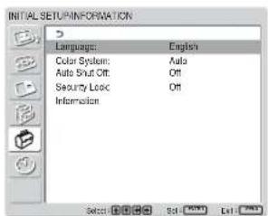
INITIAL SETUP/INFORMATION nu
You can select the on-screen language or the input signal, or set the Security Lock option.
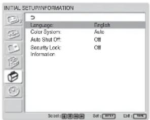
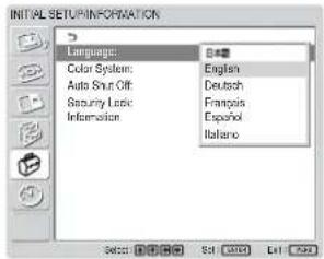
Language
Selects the on-screen language (Japanese, English, German, French, Spanish, or Italian).
For details, see “Selecting the On-screen Language” on page 36 (GB).
Color System
Selects the Color System of video signals.
Auto: to set the Color System automatically.
NTSC: to display NTSC signals
NTSC4.43: to display NTSC4.43 signals
PAL: to display PAL signals
SECAM: to display SECAM signals
PAL-M: to display PAL-M signals
PAL-N: to display PAL-N signals
PAL60: to display PAL60 signals
Auto Shut Off
When you set this item to “On,” the display unit automatically enters the standby mode when a signal is not input to the COMPONENT or DVI input connectors for more than about five minutes. The display unit automatically enters the power saving mode when a signal is not input to the DVI or RGB input connectors for more than about thirty seconds. While in the standby mode, press the ⏻POWER switch on the display unit or the POWER ON button on the Remote Commander to switch the display unit on. While in the power saving mode, the display unit is automatically turned on when a signal is input.
Using On-screen Menus
Security Lock
Sets the security lock on the display unit.
Off: Disables the security lock.
On: With this item set to On, requires a password to set the security lock.
For details, see "Setting the Security Lock" on page 38 (GB).
Information
This menu is used for displaying various information, including information on the internal status of the display unit.
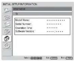
Model Name
Indicates the model name.
Serial Number
Indicates the serial number.
Operation Time
Indicates the total number of hours of operation.
Note
Time spent in standby mode is not counted as part of the Operation Time.
Software Version
Indicates the system software version.
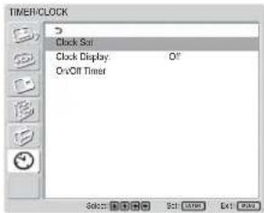
TIMER/CLOCK menu
You can set the timer, adjust time, display the built-in clock, or make the unit power on/off at a predetermined time.
Note
The time and the day are not preset in the factory setting.
Clock Set
Sets the time and the day.
For details, see "Adjusting the time and the day" on page 37 (GB).
Clock Display
Displays the currently set time on the screen when set to On.
For details, see "Displaying the time" on page 37 (GB).
On/Off Timer
Sets the time at which the power is automatically turned on or off.
For details, see "On/Off Timer Function" on page 38 (GB).
Watching the Picture
Before you start
- Power on the display.
- Power on the connected equipment and play a video source.
- To display the input signal information and Picture Mode on the screen when turning on the power or switching the input signal, set “Display” in the Custom Setup menu to On.
- To select the language of the menus, see “Selecting the On-screen Language” on page 36 (GB).
Switching the Input Signal
Input1 DVI: Selects the signal (digital RGB) input to the INPUT1 connectors.
Input2 RGB: Selects the signal (analog RGB) input to the INPUT2 connectors.
Input2 Component: Selects the signal (component) input to the INPUT2 connectors.
Option1/2 Video: Selects the signal (video signal) input from the equipment connected to the connectors of the option 1 or 2 slot.
Option1/2 S Video: Selects the signal (S video signal) input from the equipment connected to the connectors of the option 1 or 2 slot.
Option1/2 RGB: Selects the signal (analog RGB signal) input from the equipment connected to the connectors of the option 1 or 2 slot.
Option1/2 Component: Selects the signal (component signal) input from the equipment connected to the connectors of the option 1 or 2 slot.
Press INPUT1, INPUT2, OPTION1 or OPTION2 button on the Remote Commander to switch the input signal. When multiple formats of signals can be input to the selected input connector, the indication changes every time you press the corresponding button.
For example, every time you press the INPUT2 button, the indication switches to "Input2 RGB" or "Input2 Component" alternately. The selected input signal appears on the screen.
Color system or resolution/vertical frequency
You can switch the input signal using the OPTION button on the display unit.
Notes
- We recommend input source video equipment equipped with a TBC (time base corrector). If the display receives a signal without TBC, the picture may disappear due to disturbance of the sync signal.
- If signals of the same format are input from multiple systems, the Picture Quality setting will default to the most recently set value (Only when the signal formats are identical).
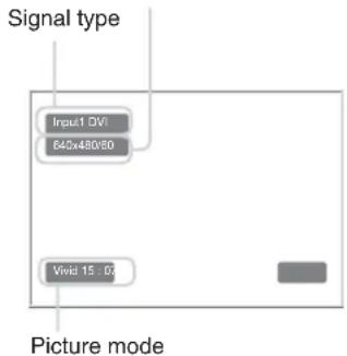
Input Signal, Picture Mode and Display Status Information
Input signal and Picture Mode information appear on the screen for about five seconds when the power is turned on or when the input signal is switched. To disable this function, follow the steps below.
1 In the CUSTOM SETUP menu, press ↑/↓ to move the cursor (yellow) to "Display" and press ENTER.
The following menu appears on the screen.
2 Press ↑/↓ to set “Display” to “Off,” then press ENTER.
To display the information
Set “Display” to “On” in step 2 above, then press ENTER. The factory default setting is “On.”
Note
You can display the input signal information and the time anytime by pressing the DISPLAY button on the Remote Commander, regardless of the above setting.
| Preset input signals | |||
| Signal name | Color system or horizontal/ vertical frequency | ||
| Computer signals | |||
| 1 | VGA ^a) -1 (VGA 350) 31.5 kHz 70 Hz | ||
| 2 | 640×480@60 Hz (VESA ^b) STD) | 31.5 kHz 60 | Hz |
| 3 | Mac ^c) 13" | 35.0 kHz 67 | Hz |
| 4 | V GA (VGA TEXT) | 31.5 kHz 70 Hz | |
| 5 | 800×600@60 Hz (VESA STD) | 37.9 kHz 60 | Hz |
| 6 | M " ac 16 | 49.7 kHz 75 | Hz |
| 7 | 1024×768@60 Hz (VESA STD) | 48.4 kHz 60 | Hz |
| 8 | 1024×768@75 Hz (VESA STD) | 60.0 kHz 75 | Hz |
| 9 | 1024×768@85 Hz (VESA STD) | 68.7 kHz 85 | Hz |
| 10 | 1152×864@75 Hz (VESA STD) | 67.5 kHz 75 | Hz |
| 11 | Mac 21 " | 68.7 kHz 75 | Hz |
| 12 | 1280×960@60 Hz (VESA STD) | 60.0 kHz 60 | Hz |
| 13 | 1280×1024@60 Hz (VESA STD) | 64.0 kHz 60 | Hz |
| 14 | 1600×1200@60 Hz (VESA STD) | 75.0 kHz 60 | Hz |
| 15 | 848×480@60 Hz (VESA STD) | 29.8 kHz 60 Hz | |
| 16 | 848×480@60 Hz (VESA STD) | 29.5 kHz 60 Hz | |
| 17 | 848×480@75 Hz 37.7 kHz 75 | Hz | |
| 18 | 1280×768@60 Hz 47.8 kHz 60 | Hz | |
| 19 | 1280×768@60 Hz 47.4 kHz 60 | Hz | |
| SDTV/HDTV | |||
| 1 | PAL PAL | ||
| 2 | NTSC NTSC | ||
| 3 | SECAM | SECAM | |
| 4 | NTSC4.43 | NTSC4.43 | |
| 5 | PAL60 | PAL60 | |
| 6 | PAL-M | PAL-M | |
| 7 | PAL-N | PAL-N | |
| 8 | 575/50i | 575/50I | |
| 9 | 480/60i | 480/60I | |
| 10 | 1080/24psf | 1080/48I | |
| 11 | 1080/50i | 1080/50I | |
| 12 | 576/50p | 576/50P | |
| 13 | 480/60p | 480/60P | |
| 14 | 1080/60i | 1080/60I | |
| 15 | 720/60p | 720/60P | |
| 16 | 720/50P | 720/50P | |
a) VGA is a registered trademark of International Business Machines Corporation, U.S.A.
b) VESA is a registered trademark of the Video Electronics Standards Association.
c) Mac (Macintosh) is a registered trademark of Apple Computer, Inc.
Notes
- When inputting an HDTV signal, input the tri-level sync signal to the 2nd pin of RGB/COMPONENT (D-sub 15 pin) on the INPUT2 connector or the BKM-FW12.
- If colors appear too light after inputting a DVD signal to the display unit, adjust the “Chroma” setting in the Adjust Picture menu.
- When the phase is readjusted, the resolution will be reduced.
Actual on-screen display of the unit's status
| On-screen display | Significance |
| 640×480 / 60 (e.g.) | The selected input signal is computer RGB. |
| 480 / 60i (e.g.) | The selected input signal is component video. |
| NTSC (e.g.) The selected input signal is NTSC. | |
| Out of Range | The input signal is out of the capture range. |
| No Sync There is no input signal. | |
| INPUT1 DVI | The signal mode of INPUT1 is set to digital RGB. |
| INPUT2 RGB | The signal mode of INPUT2 is set to analog RGB. |
| INPUT2 Component | The signal mode of INPUT2 is set to component video. |
| Option 1/2 Video | The signal mode of Option 1 or 2 slot is set to composite video. |
| Option 1/2 S Video | The signal mode of Option 1 or 2 slot is set to S VIDEO. |
| Option 1/2 RGB | The signal mode of Option 1 or 2 slot is set to analog RGB. |
| Option 1/2 The signal component | mode of Option 1 or 2 slot is set to component video. |
Selecting Image Quality
You can set an image quality suitable for the type of picture or the brightness of the location where the unit is installed.
1 Press MENU.
The main menu appears on the screen.
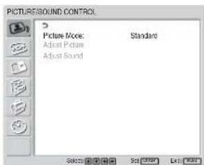
2 Press ↑/↓ to move the cursor (yellow) to "PICTURE/SOUND CONTROL" and press ENTER.
The PICTURE/SOUND CONTROL menu appears on the screen.
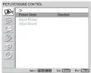
3 Press ↑/↓ to move the cursor (yellow) to "Picture Mode" and press ENTER.
The following menu appears on the screen.
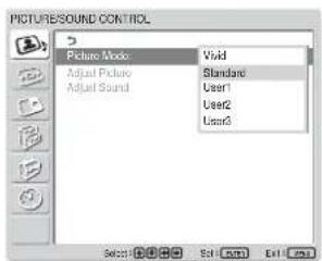
4 Select the Picture Mode with ↑/↓.
Vivid: Pictures get intense sharpness with image contour and contrast maximized.
Standard: Pictures look real with moderate contrast and image contour.
User1-3: You can set the image quality to suit your taste using the Adjust Picture menu.
5 Press ENTER to return to the PICTURE/SOUND CONTROL menu.
Adjusting the Picture
While watching the picture, you can adjust contrast, brightness, chroma, phase, and so on, to suit your taste. The adjustments can be carried out for each input signal separately. You can also store the adjusted levels in memory.
Set the Picture Mode to any of "User1" to "User3."
Adjusting the Contrast, Brightness, Chroma, and Phase, etc.
Press MENU to show the main menu and adjust "Backlight," "Contrast," "Brightness," "Chroma," "Phase," "Sharpness," "Noise Reduct.," "Cinema Drive," "Dynamic Picture," "Color Temp.," "Color Correct." or "Gamma Correct." on the Adjust Picture menu.
Backlight
Select "Backlight" with ↑/↓ and press ENTER.
Adjust the brightness of the background with // / within the range of MIN (0) to MAX (100), then press ENTER.
↑/→: to increase the brightness of the background ↓/←: to decrease the brightness of the background
Contrast
Select "Contrast" with ↑/↓ and press ENTER.
Adjust the contrast with /// within the range of MIN (0) to MAX (100), then press ENTER.
↑/→: to increase picture contrast ↓/←: to decrease picture contrast
Brightness
Select “Brightness” with / and press ENTER. Adjust the brightness with /// within the range of MIN (0) to MAX (100), then press ENTER.
↑/→: to make the picture brighter ↓/←: to make the picture darker
Chroma
Select "Chroma" with ↑/↓ and press ENTER. Adjust the chroma with ↑/↓/←/→ within the range of MIN (0) to MAX (100), then press ENTER. ↑/→: Increases color intensity. ↓/←: Decreases color intensity.
Phase
Select "Phase" with / and press ENTER. Adjust the phase with /// within the range of Left (50) to Right (50), then press ENTER. / : Makes the overall picture greenish. / : Makes the overall picture reddish.
Sharpness
Select “Sharpness” with ↑/↓ and press ENTER. Adjust the sharpness with ↑/↓/↔/→ within the range of MIN (0) to MAX (10), then press ENTER. ↑/→: Increases the sharpness of the image. ↓/←: Decreases the sharpness of the image.
Noise Reduct.
Reduces image graininess and color noise.
1 Select "Noise Reduct." with ↑/↓ and press ENTER. The following menu appears on the screen.
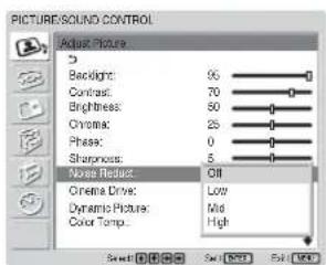
2 Select the Noise Reduct. mode with ↑/↓. Off: The image signal is displayed directly. Low: Sets the Noise Reduct. processing to low. Mid: Sets the Noise Reduct. processing to medium. High: Sets the Noise Reduct. processing to high.
3 Press ENTER to return to the Adjust Picture menu.
Cinema Drive
Automatically detects a picture shot on a 24 frame motion-picture film and plays it back maximizing the characteristics of a motion-picture film.
1 Select "Cinema Drive" with ↑/↓ and press ENTER. The following menu appears on the screen.
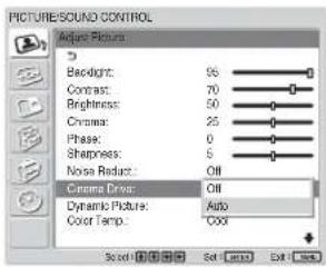
2 Select the Cinema Drive mode with ↑/↓. Off: Plays back the picture according to its signal. Auto: Plays back the picture shot on a movie film maximizing the motion-picture-like characteristics of the original.
Dynamic Picture
Enhances contrast by making white brighter and black darker.
1 Select "Dynamic Picture" with ↑/↓ and press ENTER. The following menu appears on the screen.
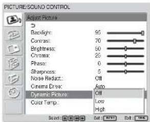
2 Select the Dynamic Picture mode with ↑/↓. Off: Disables the Dynamic Picture function. Low: Set the Dynamic Picture function to low. High: Set the Dynamic Picture function to high.
3 Press ENTER to return to the Adjust Picture menu.
Color Temp.
You can set color temperature. Either select one from "Cool," "Neutral," or "Warm," or set values for each gain separately.
1 Select "Color Temp." with ↑/↓ and press ENTER.
2 Select the color temperature with ↑/↓ and press ENTER.
Cool: Sets the color temperature to high.
Neutral: Sets the color temperature to neutral.
Warm: Sets the color temperature to low.
Color1 - 3: Sets values for each gain separately.
When you select "Warm," "Neutral," or "Cool," the menu returns to the Adjust Picture menu.
When you select "Color1" to "Color3"
(1) Press ↑/↓ to move the cursor (yellow) to the gain that you want to adjust and press ENTER.
(2) Adjust the gain (0 to 100) with ↑/↓/←/→ and press ENTER.
The menu returns to the Color Temp. menu.
Color Correct.
Faithfully reproduces a healthy complexion.
1 Select "Color Correct." with ↑/↓ and press ENTER.
The following menu appears on the screen.
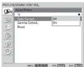
2 Select the Color Correct. mode with ↑/↓.
Off: Disables the Color Correct. function.
On: Activates the Color Correct. function.
Gamma Correct.
Balances the light and dark portions of pictures automatically.
1 Select "Gamma Correct." with / and press ENTER. The following menu appears on the screen.
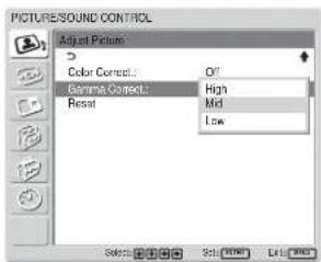
2 Select the Gamma Correct. mode with ↑/↓. High: Sets the Gamma Correct. to high.
Mid: Sets the Gamma Correct. to medium.
Low: Sets the Gamma Correct. to low.
3 Press ENTER to return to the Adjust Picture menu.
Restoring the Adjust Picture Menu Items to Their Original Settings
1 In the Adjust Picture menu, press ↑/↓ to move the cursor (yellow) to "Reset" and press ENTER. The following menu appears on the screen.
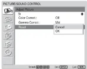
2 Press ↑/↓ to move the cursor (yellow) to "OK" and press ENTER. The Adjust Picture menu items are restored to their factory presettings.
Note
The values set for Color1 - 3 of Color Temp. will not be cleared.
To cancel the reset function
Press MENU before pressing ENTER. Alternatively, select “Cancel” with ↑/↓ and press ENTER.
Picture Enlargement
You can enlarge pictures to suite your taste. For Wide Mode, the following choices are available.
Original Picture Enlarged Picture (Picture Type)
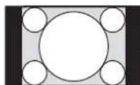

Ordinary pictures with a 4:3 aspect ratio (screen aspect ratio: 4:3).
Images are enlarged naturally to full screen size.

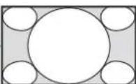
• Images from a video camera or DVD software with aspect ratio information (ID-1 type)
Images are enlarged to full screen size aligned with the right and left sides of the screen. (Black bars may remain at the top and bottom of the screen, depending on the type of picture.)

Movies filmed in CinemaVision and so forth that appear long in the horizontal direction of the screen and contain captions outside the picture (aspect ratio: 2.35:1)
The picture is displayed on the screen with the area where captions are displayed while enlarging to full screen size and aligning with the left and right sides of the screen.

Images from a video camera or DVD software containing aspect ratio information (ID-1 type)
The left and right edges of the picture are enlarged to full screen size without changing the top and bottom.

Ordinary pictures with a 4:3 aspect ratio (screen aspect ratio: 4:3).
Pictures are displayed in the original 4:3 aspect ratio without being enlarged.
Setting Auto Wide
The Auto Wide function faithfully reproduces images based on the identification control signal to identify the video signal format or enlarges various types of pictures to the optimum.
You can also enlarge picture with a 4:3 aspect ratio to 16:9.
Identification Control Signal
This is a control signal for faithfully reproducing the aspect ratio of the original image on a television screen. Images that contain this signal consist of the following:
- Images recorded with a television camera with aspect ratio information (ID-1 format).
- Television broadcasts containing a signal for setting the aspect ratio to 4:3.
1 Press MENU.
The main menu appears on the screen.
2 Press ↑/↓ to move the cursor (yellow) to "SCREEN CONTROL" and press ENTER.
The SCREEN CONTROL menu appears on the screen.
3 Press ↑/↓ to move the cursor (yellow) to "Wide Setup" and press ENTER. The following menu appears on the screen.
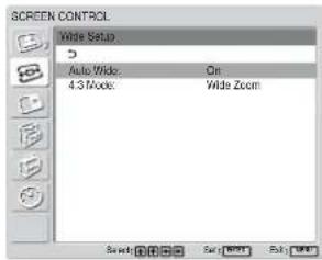
4 Press ↑/↓ to move the cursor (yellow) to "Auto Wide" and press ENTER. The following menu appears on the screen.
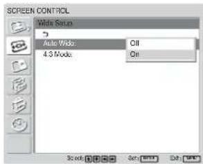
5 Select the Auto Wide setting with ↑/↓. Off: Images are reproduced as-is. On: The image is enlarged and displayed in the most appropriate aspect ratio.
6 Press ENTER. The screen returns to the screen shown in step 3.
7 Select "4:3 Mode" with ↑/↓ and press ENTER. The following menu appears on the screen.
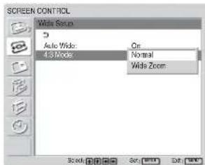
8 Select the 4:3 Mode with ↑/↓. Normal: Pictures with a 4:3 aspect ratio are displayed as-is. Wide Zoom: Pictures with a 4:3 aspect ratio are displayed after being enlarged to an aspect ratio of 16:9.
9 Press ENTER. The menu returns to the Wide Setup menu.
Note
While inputting DVI or RGB signals, you cannot set the Auto Wide because the Auto Wide function does not work.
Setting the Aspect
Pictures can also be enlarged to the desired wide mode regardless of the type of picture.
1 In the SCREEN CONTROL menu, press ↑/↓ to move the cursor (yellow) to "Aspect" and press ENTER. The following menu appears on the screen.
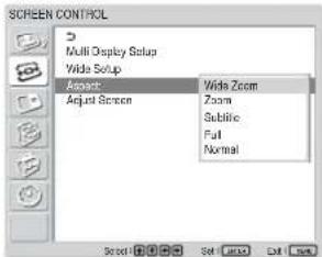
2 Select the Aspect with / .
Wide Zoom: Enlarges 4:3 pictures full-screen to 16:9 pictures. (You cannot select Wide Zoom while inputting signals from a computer.)
Zoom: Enlarges the picture all the way to the left and right edges of the screen. (Black bars may remain on the top and bottom of the screen, depending on the type of picture.)
Subtitle: Enlarges the picture all the way to the left and right edges of the screen and compresses only the area where captions are displayed.
Full: Extends the left and right sides of the picture to cover the entire screen without changing the top and bottom.
Normal: Displays the picture without enlarging it.
3 Press ENTER.
The menu returns to the SCREEN CONTROL menu.
Notes
- You cannot set the Aspect while using the PICTURE AND PICTURE function or the Multi Display.
- If you set Aspect, the Auto Wide function is disabled. If you want to use the Auto Wide function, reset it to “On.”
- The top or bottom of the picture may be cut off or the captions may not completely be displayed on the screen depending on the type and size of picture.
- Please note that showing enlarged/compressed pictures for commercial purposes or public viewing at hotels or coffee shops can be copyright infringement as defined under the copyright laws.
Resizing and Positioning the Picture
You can shift the position of the picture to fit the screen, or adjust the vertical and horizontal size of the picture separately.
Adjusting the Size, Position, or the Pixels of the Picture
Press MENU to show the main menu and adjust "Dot Phase," "Total H Pixel," "H Size," "H Shift," "V Size," or "V Shift" on the Adjust Screen menu.
Adjust screen
If there is too much noise on the edges of characters or vertical lines or if the size or position of the picture is improper, adjust the screen.
1 Select "Adjust screen" with ↑/↓ and press ENTER.
The following menu appears on the screen.
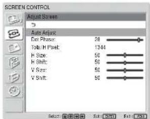
2 You can adjust the screen either automatically or manually.
Adjusting automatically
(1) Select "Auto Adjust" with ↑/↓ and press ENTER.
The following menu appears on the screen.
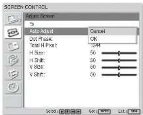
(2) Select "OK" with ↑/↓ and press ENTER. All the items of "Adjust screen" menu are adjusted automatically.
Note
Due to patterns in the image, there may be times when noise continues to occur even after you have used Auto Adjust. In such cases, adjust the dot phase manually.
Adjusting manually
(1) Select the item you want to adjust and press ENTER.
The following appears on the screen. (When you select "Dot Phase")

(2) Adjust the screen with ↑/↓/←/→, then press ENTER.
Dot Phase
Select "Dot Phase" with ↑/↓ and press ENTER. Adjust the dot phase with ↑/↓/←/→ until the characters and vertical lines appear best, then press ENTER.
Note
This item is valid only for an analog computer signal.
Total H Pixel
Select "Total H Pixel" with ↑/↓ and press ENTER. Adjust the total number of horizontal pixels with ↑/↓/←/→ until the characters and vertical lines appear best, then press ENTER. (All the items of "Adjust Screen" menu will be readjusted automatically, based on the Total H Pixel that has been adjusted manually.)
Note
This item is valid only for an analog computer signal.
H Size
Select “H Size” with ↑/↓ and press ENTER. Adjust the horizontal size of the picture with ↑/↓/↔/→ within the range of MIN (0) to MAX (100), then press ENTER.
↑/→: Enlarges the image horizontally. ↓/←: Compresses the image horizontally.
When you want to reset H Size to the center value, select "Auto Adjust."
H Shift
Select “H Shift” with / and press ENTER. Adjust the position of the picture horizontally with /// within the range of MIN (0) to MAX (100), then press ENTER.
/ : Moves the picture to the right. / : Moves the picture to the left.
When you want to reset H Shift to the center value, select “Auto Adjust.”
V Size
Select “V Size” with / and press ENTER. Adjust the vertical size of the picture with /// within the range of MIN (0) to MAX (100), then press ENTER.
/ : Enlarges the image vertically. / : Compresses the image vertically.
When you want to reset V Size to the center value, select “Auto Adjust.”
V Shift
Select “V Shift” with / and press ENTER. Adjust the position of the picture vertically with /// within the range of MIN (0) to MAX (100), then press ENTER.
↑/→: Moves the picture up. ↓/←: Moves the picture down.
When you want to reset V Shift to the center value, select “Auto Adjust.”
Viewing two pictures at the same time
You can show two pictures from different signal sources, such as a computer and a video, side by side.
1 Press MENU.
The main menu appears on the screen.
2 Press ↑/↓ to move the cursor (yellow) to "PICTURE AND PICTURE (PAP)" and press ENTER.
The PICTURE AND PICTURE (PAP) menu appears on the screen.
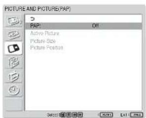
3 Press ↑/↓ to move the cursor (yellow) to "PAP" and press ENTER.
The following menu appears on the screen.
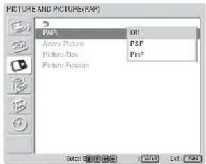
4 Select the PAP mode with / .
Off: Disables PAP function.
P&P: Shows two pictures side by side at the same time.
PinP: Shows an inset picture on the main picture.
5 Press ENTER to return to the previous screen.
Activating a picture or swapping the positions of two pictures
When P&P is selected
1 Press ↑/↓ to move the cursor (yellow) to "Active Picture" and press ENTER.
The following menu appears on the screen.
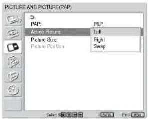
2 Select the Active Picture mode with ↑/↓ and press ENTER.
When you make the menu appear, the frame appears around the picture for which you can currently adjust the setting.
Left: Activates the picture on the left.
Right: Activates the picture on the right.
Swap: Swaps the position of the two pictures.
When PinP is selected
1 Select "Active Picture" with ↑/↓ and press ENTER.
The following appears on the screen.
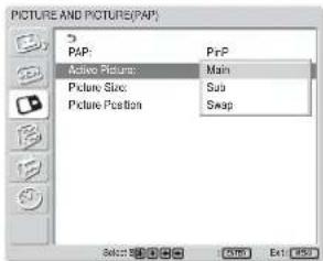
2 Select the Active Picture mode with ↑/↓ and press ENTER.
When you make the menu appear, the frame appears around the picture for which you can currently adjust the setting. The audio corresponding to the currently active picture is output.
Main: Activates the main picture.
Sub: Activates the inset picture.
When you make the menu appear while the sub picture is the picture for which you can currently adjust the setting, the frame appears around the sub picture.
Swap: Swaps the main and the inset pictures.
Zooming in on a picture
When P&P is selected
1 Select "Picture Size" with ↑/↓ and press ENTER.
2 Keep pressing / to change the size of the picture, then press ENTER.
When PinP is selected
1 Select "Picture Size" with ↑/↓ and press ENTER. The following appears on the screen.
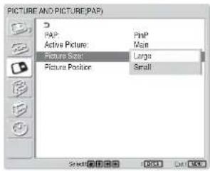
2 Press ↑/↓ to select the size, then press ENTER.
Large: Increases the size of the inset picture.
Small: Decreases the size of the inset picture.
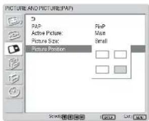
Adjusting the position of the inset picture (For PinP only)
1 Select "Picture Position" with ↑/↓ and press ENTER.
- You can show two pictures only when “Multi Display” is set to “Off.”
- While showing two pictures, the settings of "Brightness" and "Contrast" adjust the balance between the two pictures.
- You can select any of the following combinations of input signals for the PICTURE AND PICTURE function.
| PC(Digital) | + | PC(Analog) | PC | + | Video/S Video |
| Input1 | + | Input2 | Input1 | + | BKM-FW10 |
| Input1 | + | BKM-FW12 | Input2 | + | BKM-FW10 |
| Input1 | + | BKM-FW11 |
| PC | + Component | PC (Analog) | + | Digital Video |
| Input1 | + BKM-FW11 | Input2 | + | Input1 |
| Input1 | + Input2 | BKM-FW12 | + | Input1 |
| Input2 | + BKM-FW11 | BKM-FW11 | + | Input1 |
| Input1 | + BKM-FW12 | |||
| Input2 | + BKM-FW12 | |||
| Video/S video + Component | Component + Component(up to 480i) |
| BKM-FW10 + Input2 | Input2 + BKM-FW11 |
| Input2 + BKM-FW12 |
| DigitalVideo | + Component | DigitalVideo | + Video/S video |
| Input1 | + BKM-FW11 | Input1 | + BKM-FW10 |
| Input1 | + Input2 | ||
| Input1 | + BKM-FW12 |
Recommended combinations
- 2 motion pictures of different TV systems may not be displayed properly due to difference in the signal format.
Setting up the Multi Display
You can make settings for connecting multiple display units to form a video wall.
1 Press MENU.
The main menu appears on the screen.
2 Select "SCREEN CONTROL" with ↑/↓ and press ENTER.
The SCREEN CONTROL menu appears on the screen.
Note
You can enlarge the picture using the Multi Display only when "Aspect" is set to "Full."
3 Select "Multi Display Setup" with ↑/↓ and press ENTER.
The Multi Display Setup menu appears on the screen.
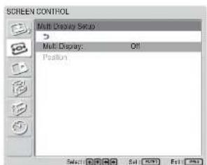
4 Select "Multi Display" with ↑/↓ and press ENTER.
The following menu appears on the screen.
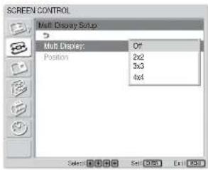
5 Select the mode corresponding to the arrangement of the video wall you want to setup with ↑/↓.
Off: Uses a single screen.
2 × 2 - 4 × 4 : Selects the arrangement to be used to construct the video wall.
6 Press ENTER to return to the Multi Display Setup menu and select "Position" with ↑/↓.
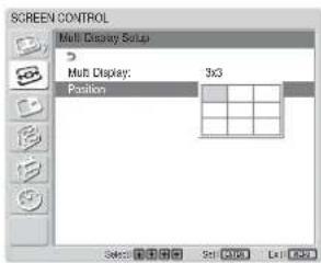
7 Select the position of this particular display unit in the arrangement of the video wall with ///
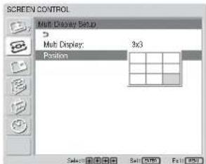
For example, to select the position at the right bottom in a 3 × 3 arrangement
8 Press ENTER to set the position. The menu returns to the Multi Display Setup menu.
Note
You can set the Multi Display only when the "PICTURE AND PICTURE" function is disabled.
Adjusting the Sound Quality
When a speaker SS-SP42FW/32FW (not supplied) installed, you can adjust sound treble level, bass level, or balance of the speaker (left and right) volume. The surround mode can also be set.
Adjusting the Treble, Bass, and Balance, etc.
Press MENU to show the main menu and adjust “Treble,” “Bass,” “Balance,” or “Surround” from the Adjust Sound menu.
Treble
Select "Treble" with ↑/↓ and press ENTER.
Adjust the treble with /// within the range of MIN (-50) to MAX (50), then press ENTER.
↑/→: Increases sound treble.
↓/←: Decreases sound treble.
Bass
Select "Bass" with ↑/↓ and press ENTER.
Adjust the bass with /// within the range of MIN (-50) to MAX (50), then press ENTER.
↑/→: Increases sound bass.
↓/←: Decreases sound bass.
Balance
Select "Balance" with ↑/↓ and press ENTER.
Adjust the balance with /// within the range of LEFT (50) to RIGHT (50), then press ENTER.
↑/→: Increases the volume on the right side.
↓/←: Increases the volume on the left side.
Surround
Select the Surround mode according to the type of picture.
1 Select "Surround" with ↑/↓ and press ENTER.
2 Select the Surround mode with ↑/↓ and press ENTER.
Off: No surround output
Hall: When desiring to give the stereo sound of movies or music programs a greater sense of presence.
Simul.: When desiring to give ordinary monaural programs or news telecasts an enhanced sense of presence using simulated stereo sound.
Restoring the Adjust Sound Menu Items to Their Original Settings
1 In the Adjust Sound menu, press ↑/↓ to move the cursor (yellow) to "Reset" and press ENTER.
The following menu appears on the screen.
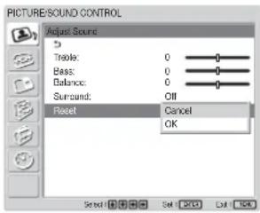
2 Press ↑/↓ to move the cursor (yellow) to "OK" and press ENTER.
The Adjust Sound menu items restore their factory presettings.
To cancel the reset function
Press MENU before pressing ENTER. Alternatively, select “Cancel” with ↑/↓ and press ENTER.
Selecting the On-screen Language
You can select the on-screen language from Japanese, English, German, French, Spanish or Italian.
1 Press MENU.
The main menu appears on the screen.
2 Press ↑/↓ to move the cursor (yellow) to "INITIAL SETUP/INFORMATION" and press ENTER.
The INITIAL SETUP/INFORMATION menu appears on the screen.
3 Press ↑/↓ to move the cursor (yellow) to "Language" and press ENTER.
The following menu appears on the screen.
4 Press ↑/↓ to move the cursor (yellow) to the language of your choice and press ENTER.
The on-screen language is switched to the one you have selected.
日本語: Japanese
English: English
Deutsch: German
Français: French
Español: Spanish
Italiano: Italian
Adjusting Color Matrix
You can set Color Matrix to show pictures in natural colors when a signal with a signal format (480I(525I), 480P(525P), 1080I(1125I), or 720P(750P)) is input to the component input adapter.
1 Press MENU.
The main menu appears on the screen.
2 Press ↑/↓ to move the cursor (yellow) to "CUSTOM SETUP" and press ENTER. The CUSTOM SETUP menu appears on the screen.
3 Press ↑/↓ to move the cursor (yellow) to "Color Matrix" and press ENTER. The following menu appears on the screen.
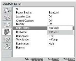
4 Select the color matrix with / .
Y/CB/CR: When the signal format is 480I or 480P.
Y/PB/PR: When signal format is 1080I or 720P.
Refer to the operating instructions of each device for details on the settings.
5 Press ENTER to return to the previous screen.
Controlling Power On/Off Automatically (Timer Function)
You can set the time to display the current time and set the time when the power automatically turns on/off (On/Off Timer function).
Adjusting the time and the day
1 In the TIMER/CLOCK menu, press ↑/↓ to move the cursor (yellow) to “Clock Set” and press ENTER.
The following menu appears, and the background color of the time turns to yellow.
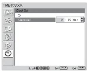
2 Adjust the hour with ↑/↓ and press ENTER. The setting for the hour is entered and the background of the minute is displayed in yellow.
3 Adjust the minute with / and press ENTER. The setting for the minute is entered and the background of the day display turns to yellow.
4 Set the day with ↑/↓ and press ENTER. The day is set and the screen returns to the previous screen.
5 Press MENU.
The display returns to the normal screen. If you must make further adjustments, or the setting must be made again, repeat the process from step 1.
Note
If the built-in clock tends to lose time, the internal battery may be exhausted. Please contact your authorized Sony dealer to have the battery replaced.
Displaying the time
1 In the TIMER/CLOCK menu, press ↑/↓ to move the cursor (yellow) to "Clock Display" and press ENTER.
The following menu appears on the screen.
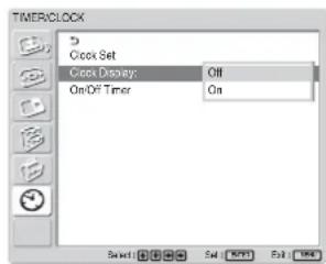
2 Select "On" with ↑/↓, then press ENTER. When you hide the menu, the clock appears on the lower right corner of the screen.
When you press the DISPLAY button on the Remote Commander, the signal currently input and the Picture Mode appear.
If the information is displayed undisturbed for about 5 seconds while the clock appears, it will disappear automatically.
“Clock Display : ON” will be saved even after the unit is powered off.
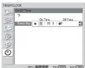
On/Off Timer Function
1 In the TIMER/CLOCK menu, press ↑/↓ to move the cursor (yellow) to "On/Off Timer" and press ENTER.
The following menu appears on the screen.
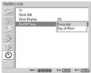
2 Select either "Every day" or "Day of Week" with ↑/↓ and press ENTER.
When "Day of Week" is selected, you can set a specific time for each day of a week.
When "Every day" is selected, the following screen appears on the screen.
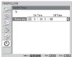
3 To set the On Time, change to with ↑/↓ and press ENTER.
4 Press ↑/↓ to set the On Time and press ENTER. The hour is set and the background of the minute display turns to yellow.
5 Press ↑/↓ to set the minute and press ENTER. Press ← to return to the screen shown in step 2.
6 Set the Off Time as you set the On Time.
7 Press ENTER. The screen returns to the screen shown in step 2.
Note
The time is not preset in the factory setting, so “-- : --” is displayed for the clock.
Setting the Security Lock
A Security Lock function is provided with the display unit. Once the Security Lock is set, the user is prompted to enter a password when the display unit is turned on, and a picture will not be displayed unless the right password is entered and you cannot use the display unit.
Note
Please keep this in mind when you use this function. We recommend writing down the password set for the display unit and keeping it in a safe place for reference. If you forget the password, consult with qualified Sony personnel.
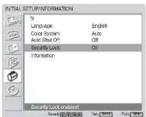
To activate the Security Lock
1 Press MENU and set "Security Lock" to "On" in the INITIAL SETUP/INFORMATION menu.
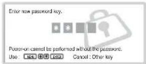
2 Enter a password.
Enter a four digit password with MENU, ↑/↓, ENTER.
("ENTER, ENTER, ENTER, ENTER" is set as the factory preset password. Press "ENTER" four times when you use this function for the first time.)

A dialog box prompting you to enter a new password appears on the screen.
(Enter a password here even when you intend to continue using the current password.)
Enter the password in the dialog box.
3 Enter the password again for re-confirmation.

The setting is finished when the following message appears.
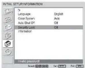
If "Invalid password!" appears on the menu screen, start the procedure again from Step 1.
4 After completing the process described above, turn off the display unit and unplug the power cord to make the setting valid.
The Security Lock becomes activated and the dialog box prompting you to enter the password appears when you turn on the display unit next time.
Security authentication
Enter the password that is set for the display unit when the dialog box prompting you to enter the password appears.
If you enter the wrong password three times, you cannot operate the display unit any further. In this situation, press the ⏻POWER switch to turn off the display unit.
To deactivate the Security Lock
Press MENU and set "Security Lock" to "Off" in the INITIAL SETUP/INFORMATION menu.
Self-diagnosis Function
The unit has a self-diagnosis function.
This function shows the display's condition based on the pattern shown by the flashing of the POWER/STANDBY indicator. The flashing pattern informs you of the display's current condition.
If the POWER/STANDBY indicator flashes, check the number of flashes and contact your authorized Sony dealer.
1 Check the flashing pattern of the POWER/STANDBY indicator.
The indicator flashes (with an image showing on the display) or flashes at intervals of three seconds (with no image showing on the display).
Count the number of flashes if the indicator flashes at intervals of three seconds. For example, the indicator flashes twice, followed by a three second pause, two more flashes and this pattern repeats. In this case, the count for the number of flashes is two.
2 Unplug the unit.
Inform your authorized Sony dealer of the number of flashes.
Operating a Specific Display With the Remote Commander
Using the supplied Remote Commander, you can operate a specific display without affecting other displays installed at the same time.
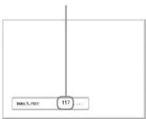
1 Press ID MODE ON on the Remote Commander. Monitor index numbers appear in black characters on the lower left menu on the screen. (Every display is allocated an individual preset index number from 1 to 255.)
For details, see "To change the index number" on page 40 (GB).

Index number
2 Input the index number of the display you want to operate using the 0 - 9 buttons on the Remote Commander.
The input number appears right next to the index number of each display.
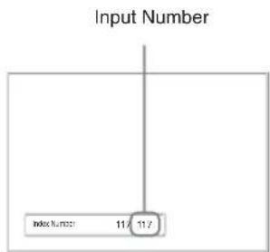
flowchart
graph TD
    A["Input Number"] --> B["Index Number: 11/11/2"]
3 Press ID MODE SET. The characters on the selected display change to green while the others change to red.

You can operate the specified display indicated with green characters only. (Power ON/STANDBY apply to the other displays, as well.)
4 When all of the setting changes have been completed, press the ID MODE OFF button. The display returns to the normal screen.

To change the index number
You can change the index number if necessary. When you change the number, use the buttons on the control button section of the display unit.
You cannot change the index number using the Remote Commander.
1 Press MENU. The main menu appears on the screen.
2 Select "CUSTOM SETUP" and press ENTER. The following appears on the screen.
3 Select "Remote" with ↑/↓ and press ENTER. The Remote menu appears on the screen.
4 Select the index number with ↑/↓ and press ENTER. The menu returns to the Remote menu.
Specifications
Video processing
Preset signal See page 23 (GB).
Sampling rate 13.5 MHz to 140 MHz
Panel system a-Si TFT Active Matrix LCD Panel
Display resolution 1366 dots (horizontal) × 768 lines (vertical)
FWD-42LX1/42LX1E:
Pixel pitch 0.681 (horizontal) × 0.681
(vertical) mm ( 132 × 132 inches)
Picture size 930 (horizontal) ×523 (vertical)
mm (36 ^5/8 × 20 ^5/8 inches)
Panel size 42-inch (diagonal 1068 mm)
FWD-32LX1/32LX1E:
Pixel pitch 0.510 (horizontal) × 0.510
(vertical) mm ( 132 × 132 inches)
Picture size 698 (horizontal) ×392 (vertical)
mm (27 12 × 15 12 inches)
Panel size 32-inch (diagonal 801 mm)
Inputs and Outputs
INPUT1
DVI DVI (DVI Specification Rev. 1.0
compliant)
AUDIO Stereo minijack (×1)
500 mVrms, high impedance
INPUT2
RGB/COMPONENT
D-sub 15-pin (female) (×1) (See
"Pin assignment" on page 42
(GB).)
AUDIO Stereo minijack (×1)
500 mVrms, high impedance
CONTROL S IN/OUT Minijack (×2)
AUDIO OUT Pinjack (×2)
500 mVrms, high impedance
REMOTE (RS-232C)
D-sub 9-pin (×1)
VIDEO/S VIDEO input/output adaptor BKM-FW10 (only for the FWD-42LX1/32LX1)
VIDEO (NTSC, PAL, SECAM, NTSC4.43, PAL60, PAL-M, PAL-N) ^1)
VIDEO IN BNC (×1)
Composite video, 1 Vp-p ±2 dB
sync negative, 75 ohms
(automatic termination)
VIDEO OUT BNC (×1) Loop-through
S VIDEO IN Mini DIN 4-pin (×1)
Y (luminance): 1 Vp-p ±2 dB sync
negative, 75 ohms terminated
C (chrominance): Burst
0.286 Vp-p ±2 dB (NTSC),
75 ohms terminated
Burst 0.3 Vp-p ±2 dB (PAL),
75 ohms terminated
S VIDEO OUT Mini DIN 4-pin (x1) Loop-through
AUDIO IN Pinjack (×2)
500 mVrms, high impedance
SPEAKER 7 W + 7 W (6 ohms), direct
unbalanced impedance:
6-16 ohms
Component/RGB Input Adaptor BKM-FW11 (For the FWD-42LX1 only)
COMPONENT/RGB IN
COMPONENT/RGB BNC (×3)
HD/VD BNC (×2)
AUDIO Stereo minijack (×1)
500 mVrms, high
impedance
General
Power requirements
100 V to 240 V AC, 50/60 Hz,
FWD-42LX1/42LX1E:
2.8 A to 1.1 A
FWD-32LX1/32LX1E:
1.7 A to 0.8 A
Power consumption
FWD-42LX1/42LX1E: 240 W
FWD-32LX1/32LX1E: 170 W
Operating conditions
Temperature: 0 °C to +35 °C
(32 °F to 95 °F)
Humidity: 20% to 90%
(no condensation)
Storing/transporting conditions
Temperature: -10^ to +40^
(14 °F to 104 °F)
Humidity: 20% to 90%
(no condensation)
Dimensions FWD-42LX1/42LX1E:
1034 × 620 × 125 ~mm
(40 34 × 24 12 × 5 inches)
FWD-32LX1/32LX1E:
802 × 492 × 107 ~mm
(31 58 × 19 38 × 4 14 inches)
(w/h/d, excluding projections)
Mass FWD-42LX1/42LX1E:
28.5 kg (62 lb 13 oz)
FWD-32LX1/32LX1E:
17.5 kg (38 lb 9 oz)
Supplied accessories
AC power cord (1)
AC plug holder (2)
Cable holder (6)
Remote Commander RM-980 (1)
Size AAA (R03) batteries (2)
Operating instructions (1)
Optional accessories
Display stand SU-42FW/32FW
Speaker SS-SP42FW/32FW
Option Adaptors for system
expansion, BKM-FW series
Safety regulations
UL1950, CSA No. 950 (c-UL),
FCC Class B, IC Class B,
EN60 950 (NEMKO), CE,
C-Tick
Design and specifications are subject to change without notice.
Pin assignment
RGB/COMPONENT connector (D-sub 15-pin)
| Pin No. Signal | |
| 1 Red video or R-Y or PR | |
| 2 Green video or Y or Sync On Green | |
| 3 Blue video or B-Y or PB | |
| 4 Ground | |
| 5 Ground | |
| 6 Red ground | |
| 7 Green ground | |
| 8 Blue ground | |
| 9 Not used | |
| 10 Ground | |
| 11 Ground | |
| 12 SDA | |
| 13 H sync or composite sync | |
| 14 V sync | |
| 15 SCL | |
AVERTISSEMENT
Raccordements 14 (FR)
Côté
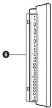
natural_image
Diagram of a vertical panel with labeled pins and connection points, no text or symbols present12 Touches ID MODE (ON/SET/OFF)
natural_image
Diagram of a mechanical device with a pair of pliers operating it, no text or symbols presentRemarques
Menu PICTURE AND PICTURE P)
±2 dB (NTSC), 75 ohms
(termination)
Slave 0,3 Vcc ± 2 dB (PAL),
75 ohms (termination)
FWD-42LX1/42LX1E: 240 W
FWD-32LX1/32LX1E: 170 W
Dimensions FWD-42LX1/42LX1E:
1034 × 620 × 125 ~mm
(40 3/4 × 24 1/2 × 5 pouces)
FWD-32LX1/32LX1E:
802 × 492 × 107 mm
(31 5/8 × 19 3/8 × 4 1/4 pouces)
Masse FWD-42LX1/42LX1E: 28,5 kg
(62 lb 13 oz)
FWD-32LX1/32LX1E: 17,5 kg
(38 lb 9 oz)
Accessoires fournis
UL1950, CSA No. 950 (c-UL),
FCC Class B, IC Class B,
EN60 950 (NEMKO), CE,
C-Tick
Seite
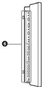
natural_image
Diagram of a vertical panel with labeled pins and a numbered marker (no text or symbols on the panel itself)① Anzeigebereich
① RGB/COMPONENT IN (D-Sub, 15-polig):
② RGB/COMPONENT OUT (D-Sub, 15-polig):
natural_image
Technical line drawing of a mechanical component with dimension label (10), no readable text or symbols present.Einheit: cm
natural_image
Diagram of a mechanical device with a tool and wires, no text or symbols presentHinweise
Menü PICTURE AND PICTURE
(PAP)
FWD-42LX1/42LX1E: 240 W
FWD-32LX1/32LX1E: 170 W
Betriebsbedingungen
Abmessungen FWD-42LX1/42LX1E:
1.034×620×125 mm
FWD-32LX1/32LX1E:
802 × 492 × 107 mm
FWD-32LX1/32LX1E: 17,5 kg
EN60 950 (NEMKO), CE, C-
Tick
Modelo : FWD-42LX1/42LX1E/32LX1/32LX1E
Parte posterior
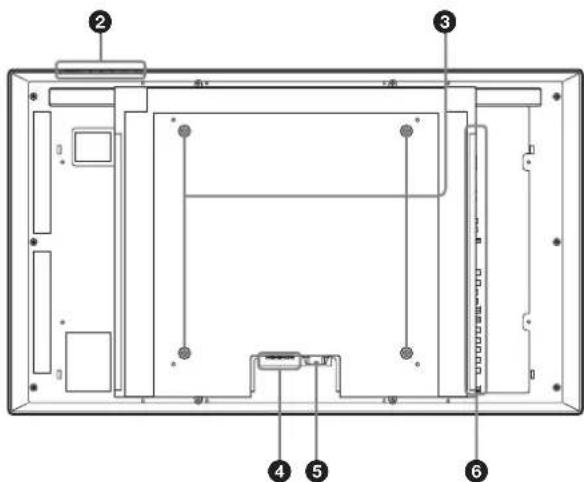
Parte lateral
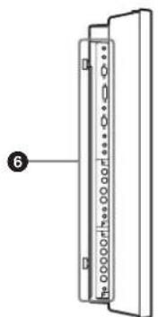
natural_image
Diagram of a vertical panel with labeled components and connection points, no readable text or symbols present③ Conectores INPUT1 (DIGITAL RGB IN)
natural_image
Technical line drawing of a mechanical component with hatched ground and dimension label (no text or symbols)natural_image
Diagram of a mechanical device with a pair of pliers attached to a shaft (no text or symbols)Notas
Menú PICTURE AND PICTURE P)
FWD-42LX1/42LX1E: 240 W
FWD-32LX1/32LX1E: 170 W
Dimensiones FWD-42LX1/42LX1E:
1.034 × 620 × 125 ~mm
(40 3/4 × 24 1/2 × 5 pulgadas)
FWD-32LX1/32LX1E:
802 × 492 × 107 ~mm
(31 58 × 19 38 × 4 14 pulgadas)
(an/al/prf, partes salientes
excluidas)
Peso FWD-42LX1/42LX1E:
28,5 kg (62 lb 13 oz)
FWD-32LX1/32LX1E:
17,5 kg (38 lb 9 oz)
Parte laterale
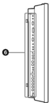
natural_image
Diagram of a vertical panel with labeled pins and connection points, no text or symbols present③ Connettori INPUT1 (DIGITAL RGB IN)
⑫ Tasti ID MODE (ON/SET/OFF)
natural_image
Technical line drawing of a mechanical assembly with dimension label (10) and hatched ground surface (no text or symbols)Unità: cm
natural_image
Line drawing of a mechanical device with a tool and wires, no text or symbols presentNote
Menu PICTURE AND PICTURE P)
DIFFUSORE 7 W + 7 W (6 ohm), impedenza
FWD-42LX1/42LX1E: 240 W
FWD-32LX1/32LX1E: 170 W
Dimensioni FWD-42LX1/42LX1E:
1.034×620×125 mm
FWD-32LX1/32LX1E:
802 × 492 × 107 ~mm
(1/a/p, escluse le parti sporgenti)
Peso FWD-42LX1/42LX1E: 28,5 kg
FWD-32LX1/32LX1E: 17,5 kg
Pile R03 (formato AAA) (2)
UL1950, CSA N. 950 (c-UL), FCC
Class B, IC Class B, EN60 950
(NEMKO), CE, C-Tick
后视图
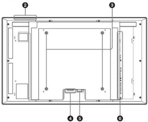
侧视图
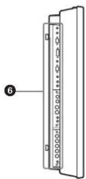
natural_image
Diagram of a vertical panel with labeled components and connection points, no readable text or symbols present.①指示灯部分
(仅限于 FWD-42LX1/42LX1E)
①RGB/COMPONENT IN (D-sub 15 芯):
②RGB/COMPONENT OUT (D-sub 15 芯):
natural_image
Technical drawing of a vertical panel with a shaded side, showing dimension line and measurement marker (no text or symbols)单位:cm
注
natural_image
Diagram of a mechanical device with a tool and wires, no text or symbols present注
natural_image
Pure mechanical diagram showing a vertical pipe with internal flow arrows, no text or symbols present电缆仓盖
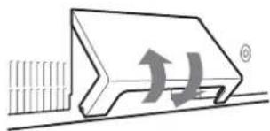
natural_image
Diagram of a mechanical component with directional arrows indicating motion or force (no text or symbols)电缆仓盖(底部)
使用电缆夹
PICTURE AND PICTURE (PAP) 菜单
CUSTOM SETUP(用户设定)菜单
可以减少电源消耗或设置各种模式。
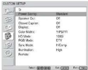
Power Saving (节电)
Standard:不节能
Reduce:节能
Language(语言)
选择 “Color1” 至 “Color3” 时
Gamma Correct. (伽马校正)
2 按↑/↓键将光标(黄色)移到“SCREEN CONTROL”处并按 ENTER 键。
2 按 ↑/↓ 键将光标(黄色)移到 “INITIAL SETUP/INFORMATION” 处并按 ENTER 键。
3 按↑/↓键将光标(黄色)移到“Language”菜单处并按 ENTER 键。
以下菜单出现在显示器屏幕上。
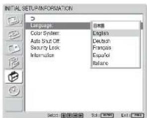
2 按↑/↓键将光标(黄色)移动“CUSTOM SETUP”处并按 ENTER 键。
4 用 ↑/↓ 键选择色彩矩阵。
DVIDVI (DVI 规格 Rev. 1.0 兼容)
AUDIO 立体声微型插孔 ( ×1 )
500 mVrms,高阻抗
INPUT2
RGB/COMPONENT
D-sub 15 芯(内插式)(×1)
(参见第 42 页 (CS) 上的
“管脚配置”。)
AUDIO 立体声微型插孔 (×1)
500 mVrms,高阻抗
CONTROL S IN/OUT 微型插孔 (×2)
AUDIO OUT 管脚插孔 (×2)
500 mVrms,高阻抗
REMOTE (RS-232C)
D-sub 9 芯型 (×1)
电源消耗 FWD-42LX1/42LX1E: 240 W FWD-32LX1/32LX1E: 170 W
工作条件 温度:0℃ 至 +35℃
湿度:20% 至 90%
(无湿气凝结)
尺寸 FWD-42LX1/42LX1E:
$$ 1 0 3 4 \times 6 2 0 \times 1 2 5 \mathrm{mm} $$
$$ \mathrm{FWD-32LX1/32LX1E}: $$
$$ 8 0 2 \times 4 9 2 \times 1 0 7 \mathrm{mm} $$
(宽/高/厚,不包括突出部分)
重量 FWD-42LX1/42LX1E : 28.5 kg
FWD-32LX1/32LX1E: 17.5 kg
附件 交流电源线(1)
交流插头固定器(2)
电缆夹 (6)
遥控器 RM-980 (1)
AAA 尺寸(R03)电池(2)
使用说明书(1)
FCC Class B, IC Class B,
EN60 950 (NEMKO), CE,
C-Tick
设计和规格若有变更,恕不另行通知。
管脚配置
Printed on 100% recycled paper.
Sony Corporation Printed in Japan


- FWD-42LX1/32LX1/42LX1E/32LX1E
- 安全のために
- ①インジケーター部
- ご注意
- To prevent fire or shock hazard, do not expose the unit to rain or moisture.
- To avoid electrical shock, do not open the cabinet. Refer servicing to qualified personnel only.
- On transportation
- For customers in the U.S.A.
- Declaration of Conformity
- For customers in Canada
- CAUTION
- Table of Contents
- Precautions 5 (GB)
- Location and Function of Parts and Controls ..... 7 (GB)
- Caution 13 (GB)
- Connections 14 (GB)
- Using On-screen Menus 16 (GB)
- Watching the Picture 21 (GB)
- Selecting Image Quality 24 (GB)
- Adjusting the Picture 24 (GB)
- Picture Enlargement 28 (GB)
- Resizing and Positioning the Picture 30 (GB)
- Viewing two pictures at the same time 32 (GB)
- Setting up the Multi Display 34 (GB)
- Adjusting the Sound Quality 35 (GB)
- Selecting the On-screen Language 36 (GB)
- Adjusting Color Matrix 36 (GB)
- Controlling Power On/Off Automatically (Timer Function).... 37 (GB)
- Setting the Security Lock 38 (GB)
- Self-diagnosis Function 39 (GB)
- Operating a Specific Display With the Remote Commander 40 (GB)
- Specifications 41 (GB)
- Precautions
- On safety
- On installation
- On the LCD panel
- On cleaning the display
- The panel surface
- The cabinet
- Notes on handling and cleaning the display panel
- On repacking
- For Customers in the United States
- Location and Function of Parts and Controls
- Front / Rear / Side
- ① Indicator section
- ② Control button section
- ③ Stand installation hooks
- ④ SPEAKER Socket
- ⑤ ∼ AC IN socket
- Connector panel
- ① Remote control detector
- ② POWER/STANDBY indicator
- ① INPUT button
- ② MENU button
- ③ ④ ↓/↑ (cursor/volume) button
- ⑤ ENTER button
- POWER switch
- Note
- Connector Panel
- ① CONTROL S IN/OUT (Control S Signal Input/Output) Connector (Minijack)
- ③ INPUT1 (DIGITAL RGB IN) connectors
- ④ INPUT2 (ANALOG RGB/COMPONENT IN) connectors
- ⑤ AUDIO OUT L/R (Pinjack)
- ⑥ VIDEO connectors (A BKM-FW10 is preinstalled only in the FWD-42LX1/32LX1.)
- ⑦ COMPONENT/RGB IN (A BKM-FW11 is preinstalled only in the FWD-42LX1.)
- ⑧ OPTION1 slot (VIDEO/COM port)
- ⑨ OPTION2 slot (VIDEO port)
- Optional adaptors (Not supplied)
- RGB/COMPONENT ACTIVE THROUGH ADAPTOR BKM-FW12 (Not supplied)
- ① RGB/COMPONENT IN (D-sub 15-pin) :
- ② RGB/COMPONENT OUT (D-sub 15-pin) :
- ③ AUDIO IN (Stereo minijack) :
- Remote Commander RM-980
- ① POWER ON switch
- ② STANDBY button
- ③ MUTING button
- ④ DISPLAY button
- ⑤ INPUT1 button
- ⑥ INPUT2 button
- ⑦ PICTURE button
- ⑧ ASPECT button
- ⑨ ↑/↓/←/→/ENTER buttons
- Number buttons
- ⑪ BRIGHTNESS button
- ⑫ ID MODE (ON/SET/OFF) buttons
- ⑬ VOLUME +/- button
- OPTION2 button
- OPTION1 button
- MENU button
- □ button
- CHROMA button
- CONTRAST +/- button
- Installing batteries
- When the Remote Commander does not work
- Provide an ample amount of space around the display
- When using the stand (not supplied)
- Connections
- Before you start
- Connecting the Speakers
- Connecting the AC Power Cord
- To remove the AC power cord
- Attaching the ferrite cores
- Notes
- Cable management
- Using the cable holders
- Using On-screen Menus
- Operating Through Menus
- Menu operating buttons
- Configuration of the menu
- Menu Guide
- PICTURE/SOUND CONTROL menu
- Picture Mode
- Adjust Picture
- Adjust Sound
- SCREEN CONTROL menu
- Multi Display Setup
- Wide Setup
- Aspect
- Adjust Screen
- PICTURE AND PICTURE (PAP)
- CUSTOM SETUP menu
- Power Saving
- Speaker Out
- Closed Caption
- Display
- Color Matrix
- HD Mode
- RGB Mode
- Sync Mode
- Illumination
- Remote
- Index Number
- Control Mode
- INITIAL SETUP/INFORMATION nu
- Language
- Color System
- Auto Shut Off
- Security Lock
- Information
- Model Name
- Serial Number
- Operation Time
- Software Version
- TIMER/CLOCK menu
- Clock Set
- Clock Display
- On/Off Timer
- Watching the Picture
- Switching the Input Signal
- Input Signal, Picture Mode and Display Status Information
- To display the information
- Selecting Image Quality
- Press MENU.
- Press ↑/↓ to move the cursor (yellow) to "PICTURE/SOUND CONTROL" and press ENTER.
- Press ↑/↓ to move the cursor (yellow) to "Picture Mode" and press ENTER.
- Select the Picture Mode with ↑/↓.
- Press ENTER to return to the PICTURE/SOUND CONTROL menu.
- Adjusting the Picture
- Adjusting the Contrast, Brightness, Chroma, and Phase, etc.
- Backlight
- Contrast
- Brightness
- Chroma
- Phase
- Sharpness
- Noise Reduct.
- Cinema Drive
- Dynamic Picture
- Color Temp.
- When you select "Color1" to "Color3"
- Color Correct.
- Gamma Correct.
- Restoring the Adjust Picture Menu Items to Their Original Settings
- To cancel the reset function
- Picture Enlargement
- Original Picture Enlarged Picture (Picture Type)
- Setting Auto Wide
- Identification Control Signal
- Press ↑/↓ to move the cursor (yellow) to "SCREEN CONTROL" and press ENTER.
- Setting the Aspect
- Resizing and Positioning the Picture
- Adjusting the Size, Position, or the Pixels of the Picture
- Adjusting automatically
- Adjusting manually
- Dot Phase
- Total H Pixel
- H Size
- H Shift
- V Size
- V Shift
- Viewing two pictures at the same time
- Activating a picture or swapping the positions of two pictures
- When P&P is selected
- When PinP is selected
- Zooming in on a picture
- Adjusting the position of the inset picture (For PinP only)
- Setting up the Multi Display
- Select "SCREEN CONTROL" with ↑/↓ and press ENTER.
- Select "Multi Display Setup" with ↑/↓ and press ENTER.
- Select "Multi Display" with ↑/↓ and press ENTER.
- Select the mode corresponding to the arrangement of the video wall you want to setup with ↑/↓.
- Press ENTER to return to the Multi Display Setup menu and select "Position" with ↑/↓.
- Select the position of this particular display unit in the arrangement of the video wall with //←/
- Press ENTER to set the position. The menu returns to the Multi Display Setup menu.
- Adjusting the Sound Quality
- Adjusting the Treble, Bass, and Balance, etc.
- Treble
- Bass
- Balance
- Surround
- Restoring the Adjust Sound Menu Items to Their Original Settings
- Selecting the On-screen Language
- Press ↑/↓ to move the cursor (yellow) to "INITIAL SETUP/INFORMATION" and press ENTER.
- Press ↑/↓ to move the cursor (yellow) to "Language" and press ENTER.
- Press ↑/↓ to move the cursor (yellow) to the language of your choice and press ENTER.
- Adjusting Color Matrix
- Press ↑/↓ to move the cursor (yellow) to "CUSTOM SETUP" and press ENTER. The CUSTOM SETUP menu appears on the screen.
- Press ↑/↓ to move the cursor (yellow) to "Color Matrix" and press ENTER. The following menu appears on the screen.
- Select the color matrix with / .
- Press ENTER to return to the previous screen.
- Controlling Power On/Off Automatically (Timer Function)
- Adjusting the time and the day
- Displaying the time
- On/Off Timer Function
- Setting the Security Lock
- To activate the Security Lock
- Security authentication
- To deactivate the Security Lock
- Self-diagnosis Function
- Operating a Specific Display With the Remote Commander
- To change the index number
- Specifications
- Video processing
- Inputs and Outputs
- INPUT1
- INPUT2
- CONTROL S IN/OUT Minijack (×2)
- REMOTE (RS-232C)
- VIDEO/S VIDEO input/output adaptor BKM-FW10 (only for the FWD-42LX1/32LX1)
- VIDEO (NTSC, PAL, SECAM, NTSC4.43, PAL60, PAL-M, PAL-N) 1)
- Component/RGB Input Adaptor BKM-FW11 (For the FWD-42LX1 only)
- COMPONENT/RGB IN
- General
- Pin assignment
- RGB/COMPONENT connector (D-sub 15-pin)
- AVERTISSEMENT
- Raccordements 14 (FR)
- Touches ID MODE (ON/SET/OFF)
- Remarques
- Menu PICTURE AND PICTURE P)
- ① Anzeigebereich
- ① RGB/COMPONENT IN (D-Sub, 15-polig):
- ② RGB/COMPONENT OUT (D-Sub, 15-polig):
- Hinweise
- Menü PICTURE AND PICTURE
- (PAP)
- ③ Conectores INPUT1 (DIGITAL RGB IN)
- Notas
- Menú PICTURE AND PICTURE P)
- ③ Connettori INPUT1 (DIGITAL RGB IN)
- ①指示灯部分
- 注
- 使用电缆夹
- PICTURE AND PICTURE (PAP) 菜单
- CUSTOM SETUP(用户设定)菜单
- Power Saving (节电)
- Language(语言)
- Gamma Correct. (伽马校正)
- 按↑/↓键将光标(黄色)移到“SCREEN CONTROL”处并按 ENTER 键。
- 管脚配置
Brand : SONY
Model : FWD-42LX1
Category : Television