NSBK-DH05 - Electronic component SONY - Free user manual and instructions
Find the device manual for free NSBK-DH05 SONY in PDF.

User questions about NSBK-DH05 SONY
0 question about this device. Answer the ones you know or ask your own.
Ask a new question about this device
Download the instructions for your Electronic component in PDF format for free! Find your manual NSBK-DH05 - SONY and take your electronic device back in hand. On this page are published all the documents necessary for the use of your device. NSBK-DH05 by SONY.
USER MANUAL NSBK-DH05 SONY
Display Accelerator Board
Installation Manual ____ GB
設置説明書 JP
Please contact your local Sony representative or dealer to request installation of this unit.
Attempting to perform the installation procedures described in this manual yourself may result in fire, electrical shock, or severe injury. Do not attempt installation yourself.
Before operating the unit, please read this manual thoroughly and retain it for future reference.
ATTENTION
The electromagnetic fields at the specific frequencies may influence the picture of this unit.
For the customers in the U.S.A.
This equipment has been tested and found to comply with the limits for a Class A digital device, pursuant to Part 15 of the FCC Rules. These limits are designed to provide reasonable protection against harmful interference when the equipment is operated in a commercial environment. This equipment generates, uses, and can radiate radio frequency energy and, if not installed and used in accordance with the instruction manual, may cause harmful interference to radio communications. Operation of this equipment in a residential area is likely to cause harmful interference in which case the user will be required to correct the interference at his own expense.
You are cautioned that any changes or modifications not expressly approved in this manual could void your authority to operate this equipment.
All interface cables used to connect peripherals must be shielded in order to comply with the limits for a digital device pursuant to Subpart B of Part 15 of FCC Rules.
This device complies with Part 15 of the FCC Rules. Operation is subject to the following two conditions: (1) this device may not cause harmful interference, and (2) this device must accept any interference received, including interference that may cause undesired operation.
For the customers in Canada
This Class A digital apparatus complies with Canadian ICES-003.
For the customers in Europe, Australia and New Zealand
WARNING
This is a Class A product. In a domestic environment, this product may cause radio interference in which case the user may be required to take adequate measures.
For the customers in Europe
The manufacturer of this product is Sony Corporation, 1-7-1 Konan, Minato-ku, Tokyo, 108-0075 Japan. The Authorized Representative for EMC and product safety is Sony Deutschland GmbH, Hedelfinger Strasse 61, 70327 Stuttgart, Germany. For any service or guarantee matters please refer to the addresses given in separate service or guarantee documents.
This apparatus shall not be used in the residential area.
To the technician installing the unit
- Please refer to the Installation Manual supplied with the NSR-500 series for installation instructions.
- Before installing the unit, be sure to unplug the NSR-500 and wait until the internal temperature drops.
Overview
This product is a display accelerator board for the Sony NSR-500 Network Surveillance Server. When installed in a slot on the main unit, this board enables enhanced video playback.
Supported models and versions NSR-500 V.1.5.1 or later
Note
For details on settings for the NSR-500 main unit and how to confirm or update the version, refer to the User's Guide (4-272-495-15 (1) or later) (CD-ROM) for the NSR-500 series.
Supported monitors
The monitors that can be used after installing this board include HDMI-compatible devices and computer displays that accept analog RGB input. The supported resolutions are as follows.
• Full HD (1,920 × 1,080)
- WUXGA (1,920 × 1,200)
(analog RGB output (monitor connector 2) only)
• Full Wide XGA (1,360 × 768)
- UXGA (1,600 × 1,200)
- SXGA (1,280× 1,024)
• XGA (1,024 × 768)
Package Contents
Check that the following items are included in this package:
- Display accelerator board (1)
- Analog RGB cable (1)
- Connector cover (1)
- Installation Manual (this document) (1)
- Warranty booklet (1)
Note
This package may contain additional hardware and/or documentation.
Parts Identification
Display Accelerator Board (installed on NSR-500)
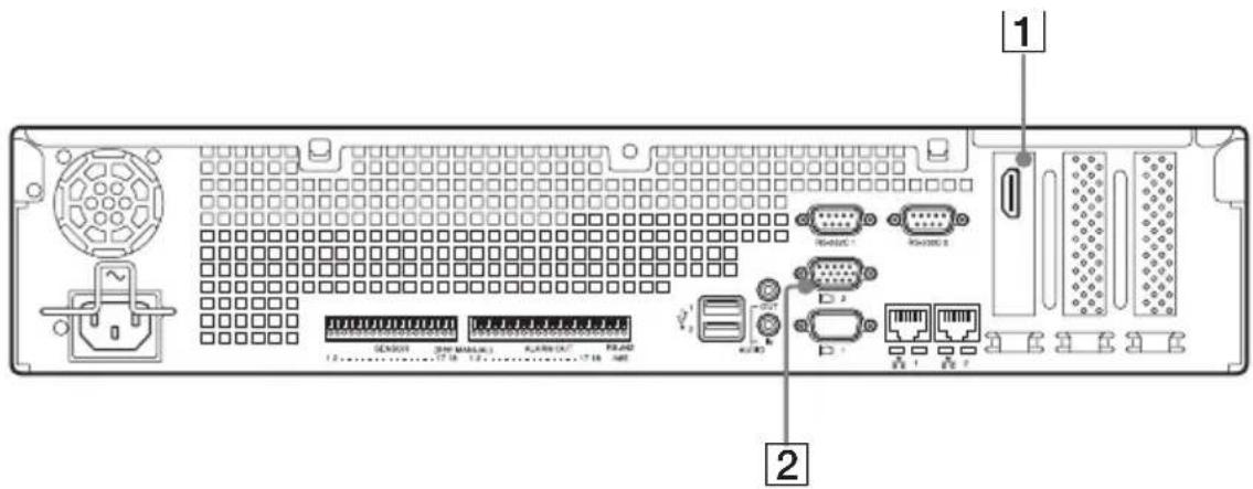
1 HDMI output connector
Use this connector to connect a monitor that supports HDMI input.
2Monitor connector 2
Use this connector to connect a monitor that supports analog RGB input.
Caution
• After this board is installed, monitor connector 1 will no longer be available for use. Only monitor connector 2 will be available.
- Monitor connector 2 and the HDMI output connector cannot be used at the same time.
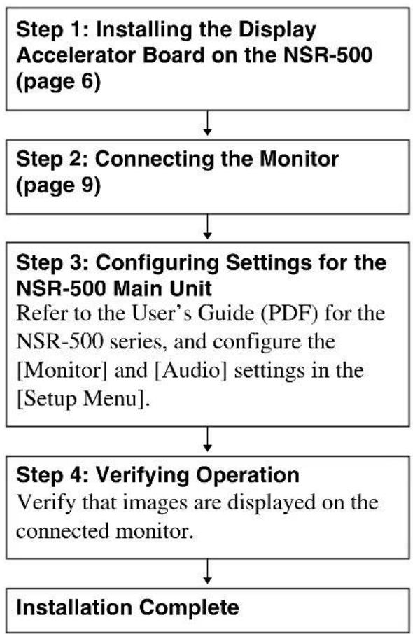
Preparation Steps Step 1: Installing the Display Accelerator Board on the NSR-500 Step 1: Installing the Display Accelerator Board on the NSR-500
flowchart
graph TD
    A["Step 1: Installing the Display Accelerator Board on the NSR-500 (page 6)"] --> B["Step 2: Connecting the Monitor (page 9)"]
    B --> C["Step 3: Configuring Settings for the NSR-500 Main Unit\nRefer to the User's Guide (PDF) for the NSR-500 series, and configure the [Monitor"] and["Audio"] settings_in_the["Setup Menu"].]
    C --> D["Step 4: Verifying Operation\nVerify that images are displayed on the connected monitor."]
    D --> E["Installation Complete"]
Caution
- Perform installation work in an antistatic environment.
- Before installing the display accelerator board, be sure to turn off and unplug the NSR-500 and wait until the internal temperature drops.
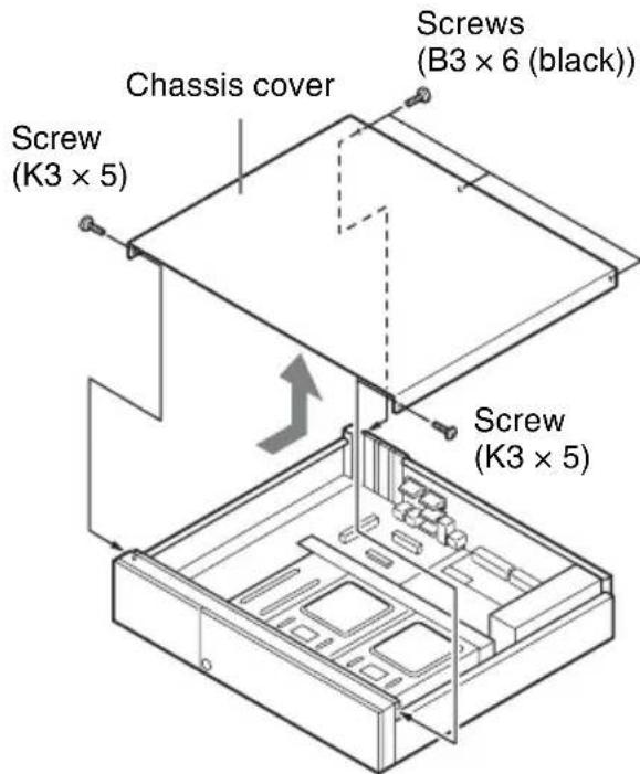
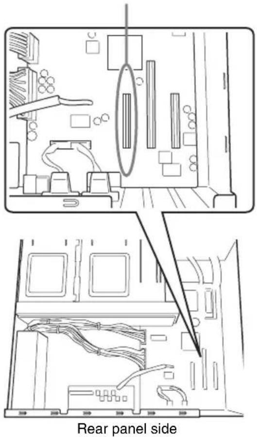
1 Remove the three screws (B3 × 6 (black)) on the rear panel of the NSR-500 and the two screws (K3 × 5) on the side panels, and then remove the chassis cover in the direction of the arrow.
2 Confirm the installation position.
Install the display accelerator board here.
3 Pull the protection cover upward and remove it.
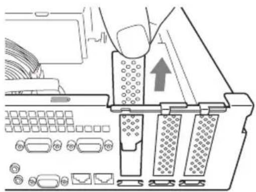
natural_image
Diagram of a computer interface showing a hand inserting a component into a slot, with no visible text or symbols.4 Insert the display accelerator board with the proper orientation.
natural_image
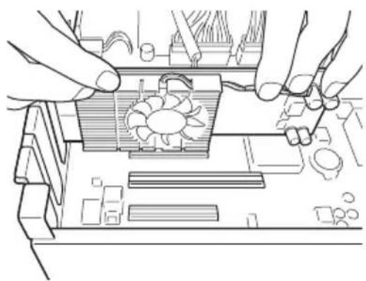
Line drawing of hands assembling a computer motherboard with a fan and circuit board (no text or symbols)5 Install the display accelerator board.
Make a visual check at the following two points and confirm that the board is firmly connected.

natural_image
Technical line drawing of a mechanical assembly with no visible text or symbolsMake a visual check.
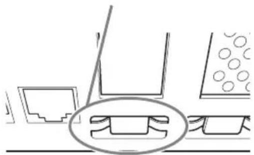
natural_image
Pure technical diagram showing mechanical components and a magnified inset of a bracket (no text or symbols)Caution
Incomplete and/or skewed insertion of the board can cause improper connection.
6 Remove the protective cover for monitor connector 2.
If secured by screws
Use a Phillips screwdriver to remove the two screws securing the protective cover.
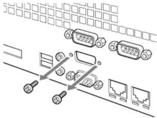
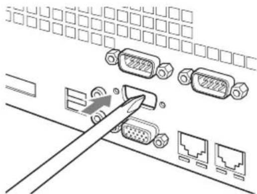
If not secured by screws
Push in the protective cover from the outside of the unit with a screwdriver, for example.
natural_image
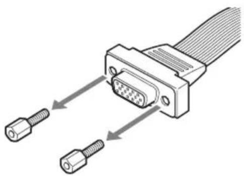
Diagram showing connections between VGA connectors and network ports (no text or symbols)7 Remove the two hex cap screws on the supplied RGB cable.
natural_image
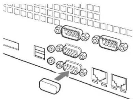
Diagram of a VGA connector with two connectors and connecting wires (no text or labels)8 Pass the 15-pin D-sub connector through the slot for monitor connector 2 from the inside of the unit, and secure the two hex cap screws to the connector from the outside of the unit.
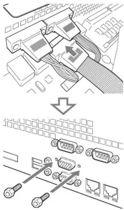
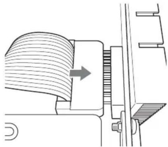
9 Orient the analog RGB cable properly, and connect it to the connector (J5) on the display accelerator board. Be sure to verify that the cable is connected securely.
natural_image
Technical line drawing of a mechanical assembly with a curved component and directional arrow (no text or symbols)10 Attach the supplied connector cover to monitor connector 1.
natural_image
Diagram showing connections between connectors and ports (no text or labels)11 Reinstall the chassis cover by performing the procedure of step 1 in reverse order.
Step 2: Connecting the Monitor
Connect the monitor to monitor connector 2 or the HDMI monitor connector.
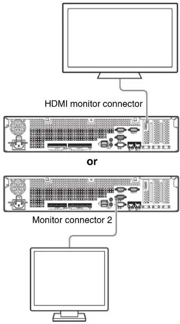
Caution
- When monitors are connected via a monitor switch, images may not always display. We recommend connecting monitors directly to the unit.
- Monitor connector 2 and the HDMI monitor connector cannot be used at the same time.
Specifications
Display accelerator board
External connector
HDMI output (1)
Analog RGB output (1)
Design and specifications are subject to change without notice.
Notes
Always verify that the unit is operating properly before use. SONY WILL NOT BE LIABLE FOR DAMAGES OF ANY KIND INCLUDING, BUT NOT LIMITED TO, COMPENSATION OR REIMBURSEMENT ON ACCOUNT OF THE LOSS OF PRESENT OR PROSPECTIVE PROFITS DUE TO FAILURE OF THIS UNIT, EITHER DURING THE WARRANTY PERIOD OR AFTER EXPIRATION OF THE WARRANTY, OR FOR ANY OTHER REASON WHATSOEVER.
Trademarks
- “IPELA” and
trademarks of Sony Corporation. - HDMI, HDMI logo, and High-Definition Multimedia Interface are trademarks or registered trademarks of HDMI Licensing LLC.
- Other products or system names appearing in this document are trademarks or registered trademarks of their respective owners. Further, the ^TM or ^® symbols are not used in the text.

お客様へ
①HDMI 出力
natural_image
Technical line drawing of a computer motherboard showing internal components and wiring (no text or symbols)リアパネル側
natural_image
Diagram of a computer interface showing a mouse interacting with the keyboard and drive bidders (no text or labels)natural_image
Line drawing of hands assembling a computer motherboard with visible fan and circuit components (no text or symbols)natural_image
Technical line drawing of a mechanical assembly with no visible text or symbolsここを確認してください。

natural_image
Pure technical diagram showing mechanical components and a magnified inset of a bracket (no text or symbols)ご注意
ネジが付いていない場合
natural_image
Diagram showing a cable inserted into a socket with multiple Ethernet connectors (no text or symbols present)natural_image
Diagram of a VGA connector with two connectors and connecting wires (no text or symbols)9
natural_image
Technical diagram of a mechanical assembly with a rotating component and housing (no text or symbols)natural_image
Diagram showing connections between connectors and ports (no text or symbols present)natural_image
Technical line drawing of a computer motherboard layout showing top and front views with circuitry and components (no text or labels)natural_image
Diagram of a device interior showing a hand inserting a component into a tray with multiple ports and connectors (no text or labels)natural_image
Line drawing of hands assembling a computer motherboard with a fan component (no text or symbols)natural_image
Technical line drawing of a mechanical assembly with no visible text or symbolsnatural_image
Pure technical diagram showing mechanical components and a magnified inset of a bracket (no text or symbols)Attention
natural_image
Diagram showing a cable connector inserted into a socket with multiple VGA connectors and network switches (no text or labels)natural_image
Diagram of a VGA connector with two connectors and connecting lines (no text or symbols)natural_image
Technical line drawing of a mechanical assembly with a curved component and directional arrow (no text or symbols)natural_image
Diagram showing connections between ports and connectors (no text or labels)natural_image
Diagram of a computer interface showing a hand inserting a component into a device with ports and connectors (no text or symbols visible)natural_image
Line drawing of hands assembling a computer motherboard with a fan and components (no text or symbols)natural_image
Technical line drawing of a mechanical assembly with no visible text or symbolsnatural_image
Pure technical diagram showing mechanical components and a magnified inset of a bracket (no text or symbols)Vorsicht
natural_image
Diagram showing a cable connector inserted into a network device with multiple VGA connectors (no text or symbols present)natural_image
Diagram of a VGA connector with two connectors and connecting lines (no text or symbols)natural_image
Technical line drawing of a mechanical assembly with a curved component and directional arrow (no text or symbols)natural_image
Diagram showing connections between electronic devices and a router (no text or symbols present)natural_image
Line drawing of hands assembling a computer motherboard with fans and components (no text or symbols)natural_image
Technical line drawing of a mechanical assembly with no visible text or symbolsnatural_image
Pure technical diagram showing mechanical components and a magnified inset of a bracket (no text or symbols)Attenzione
natural_image
Diagram showing connections between VGA connectors and network ports (no text or symbols)natural_image
Diagram showing two connectors with a central VGA connector, connected by arrows indicating connection (no text or labels present)natural_image
Technical line drawing of a mechanical assembly with a curved component and directional arrow (no text or symbols)natural_image
Diagram showing connections between electronic components including connectors, switches, and ports (no text or labels)natural_image
Line drawing of hands assembling a computer motherboard with fans and components (no text or symbols)natural_image
Technical line drawing of a mechanical assembly with no visible text or symbolsnatural_image
Pure technical diagram showing mechanical components and a magnified inset of a bracket (no text or symbols)Precaución
natural_image
Diagram showing connections between VGA connectors and network ports (no text or symbols)natural_image
Diagram of a VGA connector with two connectors and connecting pins (no text or symbols)natural_image
Technical line drawing of a mechanical assembly with a curved component and directional arrow (no text or symbols)natural_image
Diagram showing connections between electronic components including connectors, switches, and ports (no text or labels)Sony Corporation 1-7-1 Konan, Minato-ku, Tokyo, 108-0075, Japan
http://www.sony.net/
Printed in Taiwan