NSBK-EB05 - Electronic component SONY - Free user manual and instructions
Find the device manual for free NSBK-EB05 SONY in PDF.

User questions about NSBK-EB05 SONY
0 question about this device. Answer the ones you know or ask your own.
Ask a new question about this device
Download the instructions for your Electronic component in PDF format for free! Find your manual NSBK-EB05 - SONY and take your electronic device back in hand. On this page are published all the documents necessary for the use of your device. NSBK-EB05 by SONY.
USER MANUAL NSBK-EB05 SONY
Analog Encoder Board
Installation Manual ____ GB
設置説明書 JP
Before operating the unit, please read this manual thoroughly and retain it for future reference.
Note to Customers
Please contact your local Sony representative or dealer to request installation of this unit.
Attempting to perform the installation procedures described in this manual yourself may result in fire, electrical shock, or severe injury.
Do not attempt installation yourself.
ATTENTION
The electromagnetic fields at the specific frequencies may influence the picture of this unit.
For the customers in the U.S.A.
This equipment has been tested and found to comply with the limits for a Class A digital device, pursuant to Part 15 of the FCC Rules. These limits are designed to provide reasonable protection against harmful interference when the equipment is operated in a commercial environment. This equipment generates, uses, and can radiate radio frequency energy and, if not installed and used in accordance with the instruction manual, may cause harmful interference to radio communications. Operation of this equipment in a residential area is likely to cause harmful interference in which case the user will be required to correct the interference at his own expense.
You are cautioned that any changes or modifications not expressly approved in this manual could void your authority to operate this equipment.
All interface cables used to connect peripherals must be shielded in order to comply with the limits for a digital device pursuant to Subpart B of Part 15 of FCC Rules.
This device complies with Part 15 of the FCC Rules. Operation is subject to the following two conditions: (1) this device may not cause harmful interference, and (2) this device must accept any interference received, including interference that may cause undesired operation.
For the customers in Canada
This Class A digital apparatus complies with Canadian ICES-003.
For the customers in Europe, Australia and New Zealand
WARNING
This is a Class A product. In a domestic environment, this product may cause radio interference in which case the user may be required to take adequate measures.
For the customers in Europe
The manufacturer of this product is Sony Corporation, 1-7-1 Konan, Minato-ku, Tokyo, 108-0075 Japan. The Authorized Representative for EMC and product safety is Sony Deutschland GmbH, Hedelfinger Strasse 61, 70327 Stuttgart, Germany. For any service or guarantee matters please refer to the addresses given in separate service or guarantee documents.
This apparatus shall not be used in the residential area.
Precautions
To the technician installing the unit
- Please refer to the Installation Manual supplied with the NSR-500 series for installation instructions.
- Before installing the unit, be sure to unplug the NSR-500 series and wait until the internal temperature drops.
Overview
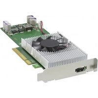
This product is an analog encoder board for the Sony NSR-500 series Network Surveillance Server.
When installed in a slot on the main unit, this board enables the connection of analog cameras.
Supported models and versions
NSR-500 series V.1.5 or later
Notes
- For details on settings for the NSR-500 series main unit and how to confirm or update the version, refer to the User's Guide (CD-ROM) for the NSR-500 series.
- Refer to the User's Guide (CD-ROM) for the NSR-500 series (4-272-495-14 (1) and later).
Package Contents
Check that the following items are included in this package:
• Analog encoder board (1)
- Analog camera input cable 9-885-163-40 (SONY) (1)
- Installation Manual (this document) (1)
- Warranty booklet (1)
Note
This package may contain additional hardware and/or documentation.
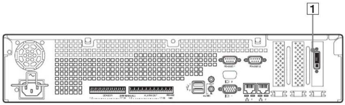
Parts Identification
Analog Encoder Board (installed on NSR-500)
Analog Camera Input Cable
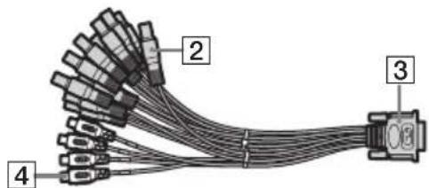
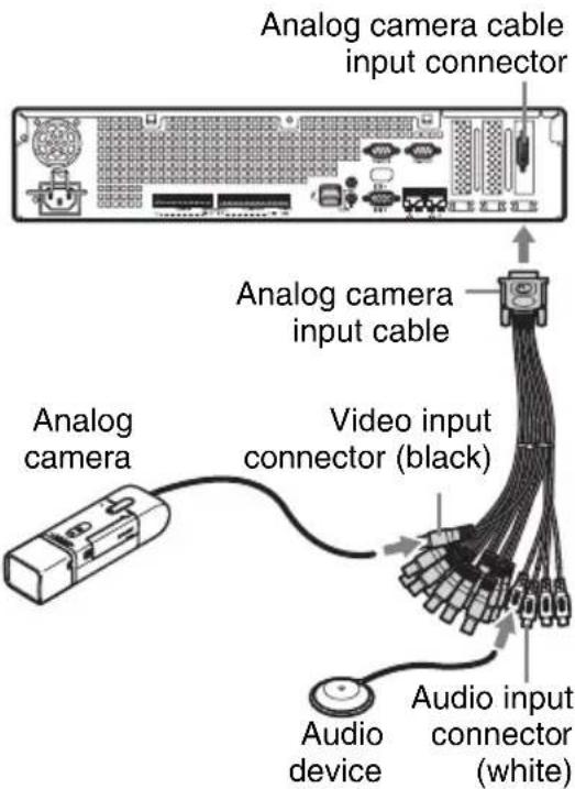
1 Analog camera cable input connector Use this connector to connect analog cameras via the supplied analog camera input cable.
CAUTION
When you connect the analog camera input cable of the unit to peripheral device, use the supplied cable to prevent malfunction due to radiation noise.
② Video input connectors × 16 (V1 to V16 (black))
Use these connectors to connect the video output connectors of analog cameras.
3 Analog encoder board connector Use this connector to connect the 1 analog camera cable input connector.
4 Audio input connectors × 4 (A1 to A4 (white))
Use these connectors to connect the output connectors of audio devices.
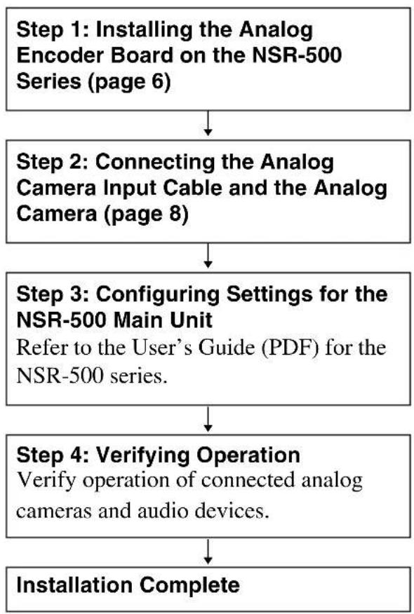
Preparation Steps Step 1: Installing the Analog Encoder Board on the NSR-500 Series (page 6)
flowchart
graph TD
    A["Step 1: Installing the Analog Encoder Board on the NSR-500 Series (page 6)"] --> B["Step 2: Connecting the Analog Camera Input Cable and the Analog Camera (page 8)"]
    B --> C["Step 3: Configuring Settings for the NSR-500 Main Unit\nRefer to the User's Guide (PDF) for the NSR-500 series."]
    C --> D["Step 4: Verifying Operation\nVerify operation of connected analog cameras and audio devices."]
    D --> E["Installation Complete"]
Caution
- Perform installation work in an antistatic environment.
- Before installing the analog encoder board, be sure to turn off and unplug the NSR-500 and wait until the internal temperature drops.
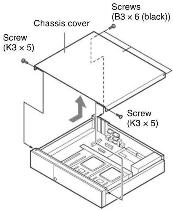
1 Remove the three screws (B3 × 6 (black)) on the rear panel of the NSR-500 series and the two screws (K3 × 5) on the side panels, and then remove the chassis cover in the direction of the arrow.
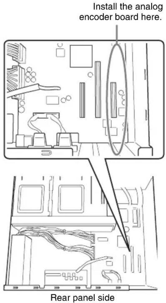
2 Confirm the installation position.
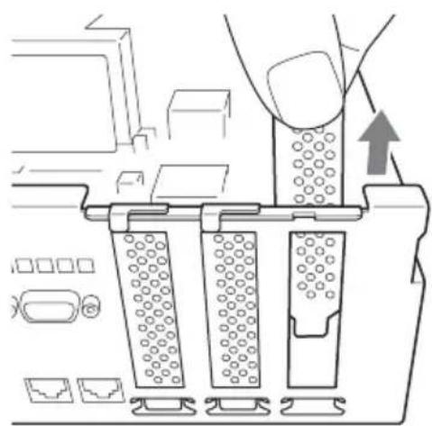
3 Pull the protection cover upward and remove it.
natural_image
Diagram of a mechanical assembly with three blocks and a directional arrow, no visible text or symbols4 Insert the analog encoder board with the proper orientation.
natural_image
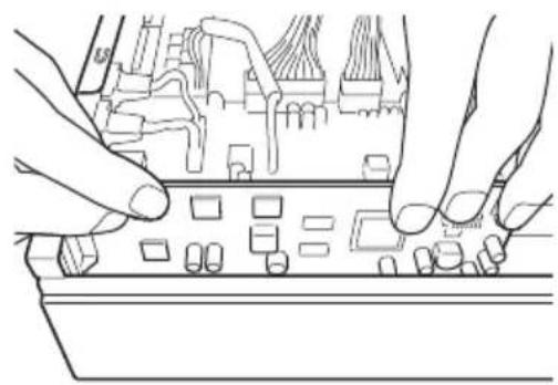
Line drawing of hands installing or adjusting a circuit board component (no text or symbols)5 Install the analog encoder board.
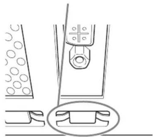
Make a visual check at the following two points and confirm that the board is firmly connected.
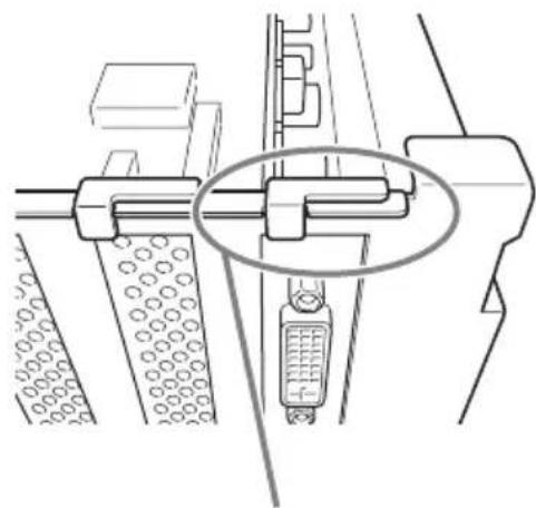
natural_image
Technical line drawing of a mechanical assembly with no visible text or symbolsMake a visual check.
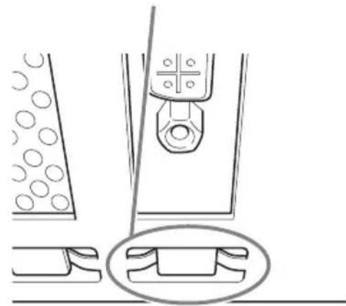
natural_image
Technical line drawing of a mechanical assembly with circular components and a central component (no text or symbols)Caution
Incomplete and/or skewed insertion of the board can cause improper connection.
6
Reinstall the chassis cover by performing the procedure of step 1 in reverse order.
Step 2: Connecting the Analog Camera Input Cable and the Analog Camera
1 Connect the supplied analog camera input cable to the analog camera cable input connector.
2 Connect the video input connector (black) of the analog camera input cable to the video output connector of the analog camera.
This cable can connect up to 16 video inputs.
3 Connect the audio input connector (white) of the analog camera input cable to the output connector of the audio device.
This cable can connect up to four audio inputs.
Caution
Do not input signals other than video signals to the video input connectors of the analog camera input cable.
4 If you want to control the analog camera, refer to the “Connections between the analog camera and the NSR-500 series for controlling pan, tilt, and zoom” section that follows, and connect the analog camera to the NSR-500 series.
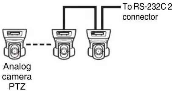
Connections between the analog camera and the NSR-500 series for controlling pan, tilt, and zoom
To control pan, tilt, and zoom on an analog camera, connect the camera control cable for the analog camera to either the RS-232C 2 connector or the RS-422/485 connector (four pins on the right side of the alarm output connector) on the NSR-500 series.
(RS-232C, RS-422, and RS-485 cannot be used together simultaneously.)
For RS-232C (VISCA) communication
Configure a daisy chain connection as follows.
Maximum number of cameras: 7
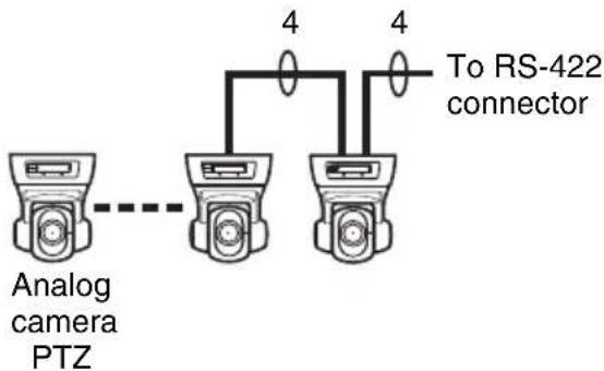
For RS-422 (VISCA) communication
Configure a daisy chain connection as follows.
Maximum number of cameras: 7
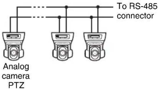
For RS-485 (PELCO-D) communication
Configure a star connection as follows. Maximum number of cameras: 16
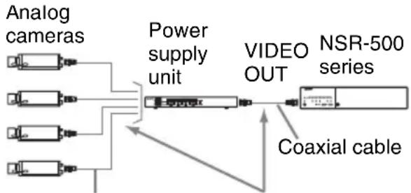
Caution
When using cameras and power supply units that superimpose DC voltage on the video coaxial cable, pay close attention to the coaxial cable wiring. If the camera cable on which DC voltage is superimposed is connected to the NSR-500 series, malfunctions may occur.
flowchart
graph LR
    A["Analog cameras"] --> B["Power supply unit"]
    C["Analog cameras"] --> B
    D["Analog cameras"] --> B
    E["Analog cameras"] --> B
    B --> F["VIDEO OUT"]
    F --> G["NSR-500 series"]
    H["Coaxial cable"] --> F
Coaxial cable on which DC voltage is superimposed
Be careful not to connect the coaxial cable for the analog cameras to the NSR-500 series.
Notes
- To perform pan, tilt, and zoom, control numbers must be configured. Be sure that the numbers do not overlap when multiple analog cameras are connected. For details on configuring control numbers, refer to the operating instructions for the analog camera.
- For details on the pin assignment for the RS-422/485 connector, refer to the Installation Manual for the NSR-500 series.
Specifications
Analog encoder board
External connector
Analog camera cable input (1)
Analog camera input cable
Video input connectors
Composite
BNC (16) (black, V1 to
V16)
1 Vp-p, 75 Ω
Audio input connectors
Pin jack (4) (white, A1 to A4)
Design and specifications are subject to change without notice.
Notes
• Always make a test recording, and verify that it was recorded successfully. SONY WILL NOT BE LIABLE FOR DAMAGES OF ANY KIND INCLUDING, BUT NOT LIMITED TO, COMPENSATION OR REIMBURSEMENT ON ACCOUNT OF FAILURE OF THIS UNIT OR ITS RECORDING MEDIA, EXTERNAL STORAGE SYSTEMS OR ANY OTHER MEDIA OR STORAGE SYSTEMS TO RECORD CONTENT OF ANY TYPE.
• Always verify that the unit is operating properly before use. SONY WILL NOT BE LIABLE FOR DAMAGES OF ANY KIND INCLUDING, BUT NOT LIMITED TO, COMPENSATION OR REIMBURSEMENT ON ACCOUNT OF THE LOSS OF PRESENT OR PROSPECTIVE PROFITS DUE TO FAILURE OF THIS UNIT, EITHER DURING THE WARRANTY PERIOD OR AFTER EXPIRATION OF THE WARRANTY, OR FOR ANY OTHER REASON WHATSOEVER.
Trademarks
- “IPELA” and are trademarks of Sony Corporation.
- Other products or system names appearing in this document are trademarks or registered trademarks of their respective owners. Further, the ^TM or ^® symbols are not used in the text.
お客様へ
natural_image
Diagram of a mechanical assembly with three cylindrical components and an upward arrow indicating motion (no text or symbols)natural_image
Line drawing of hands installing or adjusting a circuit board component (no text or symbols visible)natural_image
Technical line drawing of a mechanical assembly with no visible text or symbolsここを確認してください。
natural_image
Technical line drawing of a mechanical assembly with no visible text or symbolsご注意
natural_image
Architectural floor plan showing room layouts and equipment layout (no text or labels)natural_image
Diagram of a mechanical assembly with three vertical components and an upward arrow indicating motion (no text or symbols)natural_image
Line drawing of hands installing or adjusting a circuit board component (no text or symbols)natural_image
Technical line drawing of a mechanical assembly with no visible text or symbolsnatural_image
Technical line drawing of a mechanical assembly with no visible text or symbolsAttention
natural_image
Diagram of a mechanical device with three vertical plates and a central component, showing internal structure and movement (no text or symbols)natural_image
Line drawing of hands installing or adjusting a circuit board component (no text or symbols visible)natural_image
Technical line drawing of a mechanical assembly with no visible text or symbolsnatural_image
Technical line drawing of a mechanical assembly with circular components and a central component (no text or symbols)Vorsicht
natural_image
Diagram of a mechanical assembly with three blocks and a directional arrow, no visible text or symbolsnatural_image
Line drawing of hands installing or adjusting a circuit board component (no text or symbols visible)natural_image
Diagram of a mechanical device with three vertical plates and a central component, showing internal structure and movement (no text or symbols)natural_image
Line drawing of hands installing or adjusting a circuit board component (no text or symbols visible)5 Instale la placa codificadora analógica.
natural_image
Technical line drawing of a mechanical assembly with no visible text or symbolsnatural_image
Technical line drawing of a mechanical assembly with circular components and a central component (no text or symbols)Precaución
Sony Corporation 1-7-1 Konan, Minato-ku, Tokyo, 108-0075, Japan
http://www.sony.net/
Printed in Taiwan