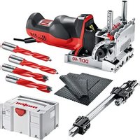
DDF40 - Drill Mafell - Free user manual and instructions
Find the device manual for free DDF40 Mafell in PDF.


| Product type | Double dowel drilling machine |
| Brand | Mafell |
| Model | DDF40 |
| Supply voltage | 230 V~ or 110 V~ (50 Hz) |
| Power consumption | 900 W |
| Rated current | 3.9 A (230 V) / 8.2 A (110 V) |
| Bit spacing | 32 mm |
| Drilling depth | 0 - 40 mm (infinitely adjustable in 1 mm steps) |
| Pivot range | 0° - 90° (with positive stops at 22.5°, 45°, 67.5°) |
| Tool diameter | 3 mm to 12.2 mm |
| No-load speed | 8000 min⁻¹ |
| Weight | 2.8 kg (without power cable) |
| Dimensions (L x W x H) | 300 x 145 x 164 mm |
| Protection class | I (mandatory grounding) |
| Sound pressure level | L_PA = 82 dB(A), uncertainty K = 3 dB(A) |
| Hand-arm vibration | 3 m/s² (according to EN 62841) |
| Safety devices | Switch lock, bit contact protection, wide supports, insulated handles |
| Maintenance | Lifetime lubrication of bearings; use special grease ref. 049040; regular cleaning; have serviced by an authorized MAFELL after-sales service |
| Spare parts | Original MAFELL accessories (carbide bits, stops, templates); exploded diagram at www.mafell.com |
| Repairability | Worn carbon brushes → after-sales service; other defects: contact dealer or MAFELL customer service |
Frequently Asked Questions - DDF40 Mafell
User questions about DDF40 Mafell
0 question about this device. Answer the ones you know or ask your own.
Ask a new question about this device
Download the instructions for your Drill in PDF format for free! Find your manual DDF40 - Mafell and take your electronic device back in hand. On this page are published all the documents necessary for the use of your device. DDF40 by Mafell.
USER MANUAL DDF40 Mafell
Duo Dowel Jointer Translation of the original operating instructions 19
natural_image
3D rendering of a mechanical power tool with visible components and no text or symbolsMAF02166/a
WARNUNG
Please read all safety instructions and directions. Failure to comply with the safety instructions and directions can cause electric shock, fire and/or serious injuries. Please retain all safety instructions and directions for future reference.
AVERTISSEMENT
GB - EC Declaration of Conformity
We herewith confirm that the machine DDF 40 complies with the EU directives quoted. The standards listed were used for design and construction.
Empowered person for the configuration of the technical documents: Mafell AG
MAF02186/a
MAF02187/a
MAF02188/a
MAF02189/a
MAF02190/a

MAF02191/a
Inhaltsverzeichnis
| 1 | Signs and symbols | 20 |
| 2 | Product information | 20 |
| 2.1 | Manufacturer's data | 20 |
| 2.2 | Machine identification | 20 |
| 2.3 | Technical data | 21 |
| 2.4 | Emissions | 21 |
| 2.5 | Scope of supply | 21 |
| 2.6 | Safety devices | 22 |
| 2.7 | Use according to intended purpose | 22 |
| 2.8 | Residual risks | 22 |
| 3 | Safety instructions | 23 |
| 4 | Setting / Adjustment | 23 |
| 4.1 | Mains connection | 23 |
| 4.2 | Chip extraction | 23 |
| 4.3 | Selection of tools | 24 |
| 4.4 | Tool change | 24 |
| 4.5 | Tilt adjustment | 24 |
| 4.6 | Drill depth adjustment | 24 |
| 4.7 | Height adjustment of tilting stop | 24 |
| 5 | Operation | 25 |
| 5.1 | Initial operation | 25 |
| 5.2 | Switching on and off | 25 |
| 5.3 | Drilling | 25 |
| 5.4 | Drilling with stop pin (Fig. 16) | 25 |
| 5.5 | Drilling with positioning on side faces (Fig. 17) | 25 |
| 5.6 | Drilling according to tracing via base plate | 25 |
| 5.7 | Drilling according to tracing via tilting stop | 25 |
| 5.8 | Vertical drilling with tilting stop | 25 |
| 5.9 | Vertical drilling with fixed distance 9.5 mm | 25 |
| 5.10 | Drilling with additional stop set ZAG (Fig. 18-25) | 25 |
| 5.11 | Drilling with position indicator PAZ according to tracing (drilling of longitudinal parts, e.g. drilling of frames) | 26 |
| 5.12 | Drilling with lateral stop set SA 320 | 26 |
| 5.13 | Drilling with trim stop LA (Fig. 24 + 25) | 27 |
| 5.14 | Drilling with dowel drilling template | 27 |
| 6 | Service and maintenance | 27 |
| 6.1 | Storage | 27 |
| 7 | Troubleshooting | 27 |
| 8 | Optional accessories | 28 |
| 9 | Exploded drawing and spare parts list | 28 |
1 Signs and symbols

This symbol appears at places where you will find instructions for your own safety.
Non-compliance with these instructions may result in very serious injuries.
This symbol indicates a potentially hazardous situation.
If this situation is not avoided, the product or objects in its vicinity may get damaged.

This symbol indicates tips for the user and other useful information.
2 Product information
in respect of machines with item number 918601, 918602, 918620, 918621, 918622, 918623, 918625, 918626
2.1 Manufacturer's data
MAFELL AG, Beffendorfer Straße 4, D-78727 Oberndorf / Neckar, Phone +49 (0)7423/812-0, Fax +49 (0)7423/812-218
2.2 Machine identification
All details required for machine identification are available on the attached rating plate.

Protection class I
Machine must be grounded for operation.

CE symbol to document compliance with the basic safety and health requirements according to Appendix I of the Machinery Directive.
For EU countries only
Do not dispose of electric tools together with household waste material!
In accordance with the European directive 2002/96/EC on waste electrical and electronic equipment and transposition into national law, obsolete electrical tools must be collected separately and recycled in an environmentally-compatible manner.

To reduce the risk of injury, please read the operating instructions.
2.3 Technical data
| Universal motor, radio and TV interference suppressed | 230 V~, 50 Hz | 110 V~, 50 Hz |
| Power input (nominal load) | 900 W | |
| Current at nominal load | 3.9 A | 8.2 A |
| Drill bit distance | 32 mm (1.26 in.) | |
| Drilling depth | 0 - 40 mm (0 - 1.57 in.) | |
| Swivel range | 0 - 90° | |
| Tool diameter maximum | 12.2 mm (4.80 in.) | |
| Tool diameter minimum | 3 mm (0.12 in.) | |
| Tool mounting hole | 8 mm (0.31 in.) | |
| Tool idling speed | 8000 rpm | |
| Outside diameter hose connector | 29 mm (1.14 in.) | |
| Weight without mains cable | 2,8 kg (6.17 lbs) | |
| Dimensions (W x L x H) | 145 x 300 x 164 mm (5.71 x 11.81 x 6.46 in.) |
2.4 Emissions
The values stated are emission levels. Although there is a correlation between emission and imission level, it cannot be reliably derived from this whether additional precautions are necessary. Factors influencing the current immission level existing at the workplace comprise the duration of exposure, the room characteristic, other sources of noise, etc. such as e.g. the number of machines and other adjacent machining operations. In addition, the permissible immission level may differ from country to country. This information is nevertheless suitable for providing the machine user with an improved assessment of the hazard and risk.
2.4.1 Noise emission specifications
Noise emission values determined according to EN 60745:
| Sound pressure level | L_PA = 82 dB (A) |
| Uncertainty | K_PA = 3 dB (A) |
| Sound power level | L_WA = 93 dB (A) |
| Uncertainty | K_WA = 3 dB (A) |
The noise measurement was recorded using the tool included in the standard equipment.
2.4.2 Vibration specifications
The typical hand-arm vibration according to EN 62841 is 3 m/s ^4 .
2.5 Scope of supply
DDF 40 MidiMAX
| Item-No. 918601, 918625 | 1 bottle of glue |
| 2 carbide-tipped dowel drill bits ø 8 mm (0.31 in.) | 2 anti-slip mats |
| 1 package wooden dowels ø 8x30 mm (approx. 200 pcs.) | 1 carrying case |
| 1 additional support plate ZA | 1 operating manual |
| 1 additional stop set ZAG | 1 folder "Safety instructions" |
| 1 hose connector |
DDF 40 MaxiMAX
Item number 918602, 918620, 918621, 918622, 918623, 918626
2 carbide-tipped dowel drill bits 6 mm (0.24 in.)
2 carbide-tipped dowel drill bits 8 mm (0.31 in.)
Further scope of delivery DDF 40 MaxiMAX:
1 package wooden dowels ø 6x30 mm (approx. 350 pcs.)
1 package wooden dowels ø 8x30 mm (approx. 200 pcs.)
1 additional support plate ZA
1 additional stop set ZAG
1 hose connector
1 lateral stop set SA 320
1 trim stop LA
1 position indicator PAZ
1 Allen key with handle
1 bottle of glue
1 dowel nozzle 8 mm (0.31 in.)
2 anti-slip mats
1 carrying case
1 operating manual
1 folder "Safety instructions"
2.6 Safety devices

Danger
These devices are required for the machine's safe operation and may not be removed or rendered inoperative.
The machine is equipped with the following safety devices:
- Switch interlock during tool change
- Protection against contact with the drill bits
- Large bearing surfaces of the base plate and tilting stop
- Handles and handle recesses
2.7 Use according to intended purpose
The duo-dowel system is exclusively designed for drilling wooden materials using the drill bits approved by us with a diameter between 3 mm and 12.2 mm (0.13 and 4.80 in.).
It is used to make connections between individual parts in the workbench area. The device is not approved for drilling holes in existing walls.

Grounded machines must be connected to a properly mounted socket outlet which is grounded in accordance with all regulations and laws. Never remove the ground contact or modify the plug in any other way. Have the socket outlet checked by a qualified electrician if you have any doubts about the proper grounding of the socket outlet.

Danger
Do not interrupt the grounding by using an adapter plug.

Make sure that the connecting cable does not touch any rotating parts.
Any other use than described above is not permissible. The manufacturer cannot be held liable for any damage arising from such other use.
In order to use the machine as intended, comply with the operating, maintenance, and repair instructions specified by Mafell.
2.8 Residual risks

Danger
Even if used in accordance with its intended purpose and despite conforming with the safety instructions, residual risks caused by the intended use will always remain.
- Touching the drill bits inside and outside the base plate.
- Touching the drill bits on the workpiece rear when drilling.
- Breakage of the drill bits and risk of the drill bits or parts of them being hurled away.
-
Ejection of chips.
-
Touching live parts with the housing open and the mains plug not removed.
- Hearing can be impaired when working for long periods without ear protectors.
- Emission of harmful wood dusts during longer operation without extraction.
3 Safety instructions

Danger
Always observe the following safety instructions and the safety regulations applicable in the respective country of use!
General instructions:
- Children and adolescents must not operate this machine. This rule does not apply to young persons receiving training and being supervised by an expert.
- Never work without the protection devices prescribed for the respective operating sequence and do not make any changes to the machine that could impair safety.
- When operating the machine outdoors, use of an earth-leakage circuit-breaker is recommended.
- Damaged cables or plugs must be immediately replaced.
- Avoid sharp bends in the cable. Especially when transporting and storing the machine, do not wind the cable around the machine.
Do not use:
- Damaged drill bits and drill bits that have changed their form.
- Blunt drill bits as they impose an excessive load on the motor.
- Drill bits that are not suitable for the drill's idling speed.
Machine-specific safety instructions:
- After drilling, the motor unit must automatically move back to its home position. The drill bits are then completely in the protective cover. If this does not happen, the machine must be switched off immediately and repaired before further use.
Instructions on the use of personal protective equipment:
- Always wear ear protectors during work.
- Always wear protective goggles during work.
- Always where a dust mark during work.
Instructions on operation:
- Do not reach with your hands into the drilling area and do not touch the drill bits. Position your second hand in the handle recesses provided for this purpose at 7 or 24 (Fig. 1 or 4).
- Do not reach under the workpiece.
- Never support the workpiece in your hand or over your leg. Secure the workpiece against a sturdy support.
- Only hold the device by its isolated handle surfaces when carrying out work during which the cutting tool could hit hidden power cables or its own connection cable.
- Before starting to drill, tighten the depth and angle adjustments.
- Examine the workpiece for foreign objects. Never attempt to drill into nails or other metal objects.
Instructions on service and maintenance:
- Regularly cleaning the machine, especially the adjusting devices and guides, constitutes an important safety factor.
- Only original MAFELL spare parts and accessories may be used. Otherwise, the manufacturer will not accept any warranty claims and cannot be held liable.
4 Setting / Adjustment
4.1 Mains connection
Prior to commissioning make sure that the mains voltage complies with the operating voltage stated on the machine's rating plate.
4.2 Chip extraction
Connect the machine to a suitable external dust extractor during all work generating a considerable amount of dust. The air velocity must be at least 20 m/s (65.6 ft / sec.).
The outside diameter of hose connector 16 (Fig. 3) is 27 mm (1.06 in.).
4.3 Selection of tools
Please use the dowel drill bits listed in chapter 8 Optional accessories.
These carbide-tipped drill bits were developed specially for the DDF 40 and are suitable for all types of wood.
4.4 Tool change

Danger
Pull the power plug during all service work.
The basic requirement for correct drilling are well ground drill bits.
Proceed as follows for the tool change:
- Set the turning knob 11 (Fig. 2) to the tool change symbol. The ON switch 1 (Fig. 1) is now blocked!
- Push the motor unit forward until it engages.
- Turn around the machine (Fig. 3).
- Now turn the tool holding fixture 18 (Fig. 3) visible in the slotted hole using the Allen key so that the screws 19 are visible in the openings of the base plate.
- Unfasten the screws with the Allen key.
- Pull off the drill bits 20 to the front.
- Push the new drill bits into the tool holding fixture up to the limit stop.
- Check the drill bits' seat. Retighten the screws 19.
- Set the turning knob to drilling depth "1" or "2". Attention, the machine automatically returns to its home position!

After the tool change, you have to check the zero setting for the drill depth and readjust it where necessary.
- Set the depth stop "1" 14 (Fig. 2) to the scale depth 0.
- Set the turning knob 11 to drilling depth "1".
- Push the motor unit 17 forward and check whether the drill tip or cutting edge (depending on your requirements!) is level with the contact surface 21 (Fig. 3).
- If necessary, turn the screw 13 at stop 12 (Fig. 2) with the enclosed Allen key until the zero position is adjusted. When delivered, this is set to the drill blade!
4.5 Tilt adjustment

The tilting stop 7 (Fig. 1) can be continuously adjusted in the range from 0° to 90°. Three latching positions facilitate a fast setting of the angles 22.5°, 45° and 67.5°.
- Unfasten the wing nut 4 (Fig. 1)
- Tilt the tilting stop to the desired angle.
- Retighten the wing nut.
4.6 Drill depth adjustment

The drilling depth can be adjusted between 0 - 40 mm in 1 mm steps.
- First press button "2" 15 (Fig. 2) and push the depth stop "2" to the large depth measurement (2 to 40 mm).
- Then press button "1" 14 (Fig. 2) and push the depth stop "1" to the small depth measurement (0 to 38 mm).
- Set the turning knob 11 (Fig. 2) to drilling depth "1" or "2" as required.
4.7 Height adjustment of tilting stop

The distance can be continuously adjusted between 6.5 and 60 mm to the drill axis.
- Unfasten the wing nut 2 (Fig. 1)
- Set the tilting stop 7 (Fig. 1) to the desired scale value using the setting wheel 5 (Fig. 1).
- Retighten the wing nut.
With the rotating revolver limit stop 3 you can select five firmly preset distances:
6.5 mm, 8 mm, 9.5 mm, 11 mm, 12.5 mm, as well as a freely adjustable distance.
For this purpose, turn the threaded pin in the revolver limit stop with an Allen key AF 2.5.
5 Operation
5.1 Initial operation
Personnel entrusted to work with the machine must be made aware of the operating instructions, calling particular attention to the chapter "Safety instructions".
5.2 Switching on and off
- Switching on: Push the ON switch 1 (Fig. 1) downwards until it engages.
- Switching off: Press ON switch 1. The ON switch jumps into off position.

The ON switch is blocked in the tool change position! Check the setting of the turning knob 11 (Fig. 2)!
5.3 Drilling
- Clamp the workpiece or prevent it from moving.
- Switch on the machine (see chapter 5.2).
- If necessary, place the machine onto the support surface of base plate 6 or tilting stop 7 (Fig. 1).
- Position the machine against the outside edge of the workpiece using one of the methods described below.
- Position your second hand in the handle recesses provided for this purpose at 7 or 24 (Fig. 1 or 4).
- Slide the motor unit over the handle hump 9 (Fig. 1) or the handle bulge 10 at the end of the motor up to the stop.
- The motor unit automatically returns to its home position. Switch off the machine.
5.4 Drilling with stop pin (Fig. 16)
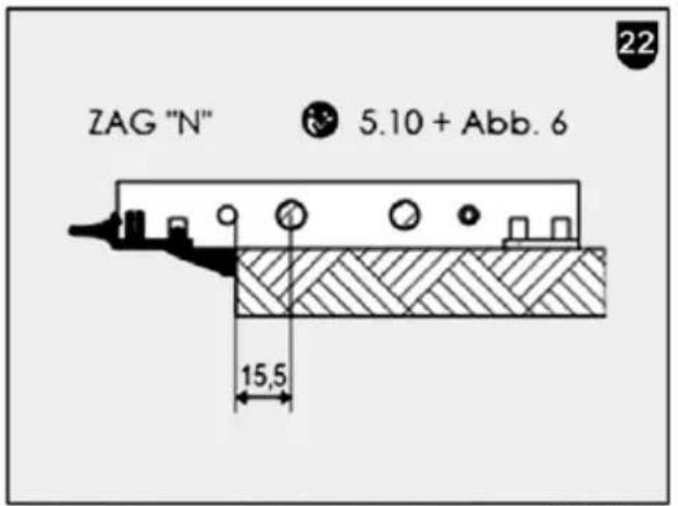
The base plate 6 (Fig. 1) is equipped with two spring-loaded stop pins 8. They are used to place the drill holes at a fixed distance of 15.5 mm to the outer edge of the workpiece. The machine stop can be positioned at the left or right.
5.5 Drilling with positioning on side faces (Fig. 17)
The base plate 6 (Fig. 1) is equipped with two contact surfaces 6a (Fig. 1). They are used to place the drill holes at a fixed distance of 49 mm to the contact surface. The machine stop can be positioned at the left or right.
5.6 Drilling according to tracing via base plate
The base plate 6 (Fig. 1) has reference markings on the top, front and bottom side for the machine centre, drill bit centre and inner sides of the stop pins or the additional stops "N". The outer reference markings on the front and top side only correspond to the leading edge of the additional stop "M" (see chapter 5.9). The reference markings on the left and right side faces 6a (Fig. 1) each correspond to the centre of the drill.
5.7 Drilling according to tracing via tilting stop
The tilting stop 7 (Fig. 1) has three reference markings. The middle reference marking corresponds to the machine centre. The reference markings on the left and right each correspond to the centre of the drill.
5.8 Vertical drilling with tilting stop
When drilling vertically (Fig. 4) with the tilting stop 7, always secure the additional support ZA 22 (Fig. 4) to the underside of the base plate with the knurled screws 23 to provide a secure support. With your free hand, press the additional support ZA against the workpiece by means of the handle support 24.
5.9 Vertical drilling with fixed distance 9.5 mm
Attach the additional support ZA 22 to the underside of the base plate using the knurled screws 23 as shown in Fig. 5 (the handle support 24 points downwards!). The additional support ZA, which protrudes 10 mm above the drilling plane, can now be used as a stop edge with 9.5 mm edge distance. The tilting stop 7 which is set to 0° ensures a secure support.
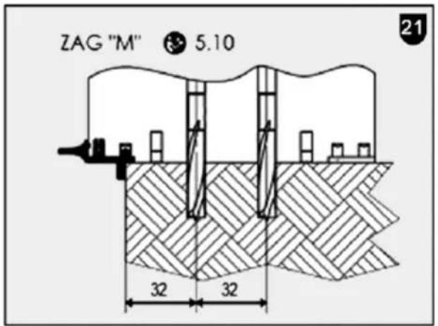
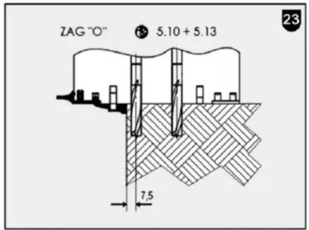
5.10 Drilling with additional stop set ZAG (Fig. 18-25)
The additional stops 25 (Fig. 6) from stop set ZAG can be inserted into contact surface 21 (Fig. 6), the underside of base plate 6 (Fig. 6) and the contact surface of tilting stop 7 (Fig. 6) with different edge distances.

For different edge distances, see sketch images on page 6.
5.11 Drilling with position indicator PAZ according to tracing (drilling of longitudinal parts, e.g. drilling of frames)

The distance can be infinitely adjusted between 19 and 60 mm to the drill axis.
- Unfasten the wing nut 2 (Fig. 1)
- Use the setting wheel 5 (Fig. 1) to move the tilting stop 7 (Fig. 1) to the very top.
- Fit the position indicator PAZ 26 (Fig. 7) onto the columns of the height guide.
- Slide the position indicator in the direction of tilting stop 7 until it engages at the tilting stop.
- Set the tilting stop 7 (Fig. 1) to the desired scale value using the setting wheel 5 (Fig. 1).
- Retighten the wing nut 2.
- The distance between the position indicator PAZ and the centre of the drill hole corresponds to the set distance of the contact surface of the tilting stop 7 (Fig. 8).
- Use the additional stop "N" on the tilting stop for right-angled alignment to the longitudinal edge of the workpiece.
5.12 Drilling with lateral stop set SA 320
5.12.1 Lateral stop for large edge distances and repositioning (flush body machining).

The edge distance can be adjusted between 105 and 320 mm in 5 mm increments to the drill centre.
The side stop 27 (Fig. 9 + 10) can be inserted alternately in 2 positions on the base plate 6 (Fig. 1).
Position 1: Mount the side stop 27 as shown in Fig. 9. The spring-loaded stop pin 30 in tab 28 is in the same direction as the stop pins in the base plate.
Position 2: Mount the side stop 27 as shown in Fig. 10. The spring-loaded stop pin 30 in tab 28 protrudes downwards beyond the contact surface of the base plate.
After inserting the side stop, check that the locking lever 31 (Fig. 9) is fully engaged.
By pressing the push-button 29 (Fig. 9) the tab 28 can be adjusted to the desired edge or repositioning distance.
5.12.2 Lateral stop for edge distance with infinitely variable fine adjustment (offset body machining)

Only useful if tab 32 is set to a minimum distance of 105 mm!
- Actuate push-button 29 (Fig. 9) and remove tab 28 completely from the stop rail.
- Slide the tab 32 (Fig. 11) with mounted roller edge guide 34 onto the stop rail and set the smallest distance 105 mm.
- Mounting the roller edge guide 34: Observe the symbols on the roller edge guide in this regard. Position the roller edge guide and push it backwards up to the stop. Close lever 37 (Fig. 11).
- Loosen the knurled nut 36 with a few turns.
- Set the knurled screw 35 to the desired distance. Adjustment travel +/- 5 mm referred to the stop pin 8 (Fig. 11). 0.1 mm travel per scale line.
- Retighten the wing nut 36.
5.12.3 Lateral stop for producing rows of holes

Only a setting to 320 mm makes sense!
(10x drilling distance 32 mm)
In this way, you avoid excessive tolerance deviations during continuous repositioning!
- Use tab 32 (Fig. 12) without the roller edge guide 34 (Fig. 11).
- Dismantling the roller edge guide 34: Observe the symbols on the roller edge guide in this regard. Open lever 37 (Fig. 11). Push roller edge guide forward and remove.
-
Mount the additional stop "K" 38 (Fig. 12) from the set ZAG on the tab 32.
-
Actuate push-button 33 (Fig. 12) and set the tab to 320 mm.
- Attach the additional stop "K" 38 in an existing drill hole and place the other drill holes in the row of holes.
- Then remove the side stop from the machine. Mount the additional stop "K" 38 directly on the base plate. Drill the missing holes between the previously inserted drill holes.
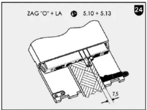
5.13 Drilling with trim stop LA (Fig. 24 + 25)

Danger
Only 1 drill bit with max. ∅ 8.2 mm may be used! Remove unused threaded pin from the machine!

The drilling distance to the stop pin is 7.5 mm!
When adjusting the drilling depth, make sure that it is reduced by 15 mm by means of the trim stop LA!
For drilling narrow strips (approx. 14 - 48 mm) and small drilling distances, use the trim stop LA 39 (Fig. 13).
- Mount only 1 piece drill bit with max. ∅ 8.2 mm. (see chapter 4.4)
- Press the locking levers 42 (Fig. 13) together at the trim stop and insert the trim stop 39 (Fig. 13) on the front side of the base plate. The trim stop can only be fitted in the correct position to the mounted drill bit!
- Use the additional stop "P" (Fig. 25) for right-angled alignment when applying it to the stop pin 40 (Fig. 13), or to the additional stop "O" (Fig. 24) from the set ZAG on the stop pin 41.
Insert these into the corresponding mountings of the tilting stop.
5.14 Drilling with dowel drilling template
For working with the dowel drilling template 43 (Fig. 14 + 15) see operating instructions of the dowel drilling template. Order no. see chapter 8 Special accessories.
For horizontal drilling, position the toothing of the tilting stop 7 against the dowel drilling template as shown in Fig. 14.
For vertical drilling, tighten the additional support ZA 22 (Fig. 4) to the underside of the base plate with the knurled screws 23. Then apply the toothing of the additional support to the dowel drilling template as shown in Fig. 15.
6 Service and maintenance

Danger
Pull the power plug during all service work.
MAFELL machines are designed to be low in maintenance.
The ball bearings used are greased for life. When the machine has been in operation for a longer period of time, we recommend to hand the machine in at an authorised MAFELL customer service shop for inspection.
Only use our special grease, order No. 049040 (1 kg tin) for all greasing points.
6.1 Storage
If the machine is not used for a longer period of time, it has to be carefully cleaned. Spray bright metal parts with a rust inhibitor.
7 Troubleshooting

Danger
Determining the causes for existing defects and eliminating these always requires increased attention and caution. Pull the mains plug beforehand!
Some of the most frequent defects and their causes are listed in the following chart. In case of other defects, contact your dealer or the MAFELL customer service.
| Defect | Cause | Elimination |
| Machine cannot be switched on | Turning knob 11 (Fig. 2) is set to "Tool change". | Set the turning knob to drilling depth "1" or "2". |
| No mains voltage | Check power supply | |
| Mains fuse defective | Replace fuse | |
| Carbon brushes worn | Take the machine to a MAFELL customer service shop | |
| Machine stops while drilling is in process | Mains failure | Check mains back-up fuses |
| Burn marks on the drill holes | Feed speed too low | Increase feed speed |
| Blunt drill bit | Regrind drill bit or replace | |
| Chip ejection blocked | Wood is too damp | |
| Extended drilling without extraction | Connect machine to an external extraction, e.g. portable dust extractor |
8 Optional accessories
- Dowel drill bit - DB HSS ∅ 3 mm (0.118 in.) Order No. 090 083
- Dowel drill bit - DB HW ∅ 5 mm (0.196 in.) Order No. 090 089
- Dowel drill bit - DB HW ∅ 6 mm (0.236 in.) Order No. 090 096
- Dowel drill bit - DB HW ∅ 6.1 mm (0.240 in.) Order No. 090 120
- Dowel drill bit - DB HW ∅ 8 mm (0.314 in.) Order No. 090 097
- Dowel drill bit - DB HW ∅ 8.1 mm (0.318 in.) Order No. 090 122
- Dowel drill bit - DB HW ∅ 8.2 mm (0.322 in.) Order No. 090 123
- Dowel drill bit - DB HW ∅ 10 mm (0.393 in.) Order No. 090 098
- Dowel drill bit - DB HW ∅ 10.1 mm (0.397 in.) Order No. 090 124
- Dowel drill bit - DB HW ∅ 10.2 mm (0,401 in.) Order No. 090 125
- Dowel drill bit - DB HW ∅ 12 mm (0,472 in.) Order No. 090 099
- Dowel drill bit - DB HW ∅ 12.2 mm (0,480 in.) Order No. 090 127
- Lateral stop set SA 320 Order No. 206 490
- Trim stop LA Order No. 206 491
- Dowel drilling template clamping device, 800 mm (31.496 in.) Order No. 203 980
- Dowel drilling template extension 1600 cpl., length 1600 mm (62.992 in.) Order No. 203 434
- Screw clamp with stop (for working with dowel drilling template extension) Order No. 093 280
- Screw clamp (for rail fixing on the workpiece) Order No. 093 281
- Wood dowel see specialised trade, DIY store etc.
9 Exploded drawing and spare parts list
The corresponding information in respect of spare parts can be found on our homepage: www.mafell.com
Sommaire
natural_image
Two black-and-white images showing mechanical components, one with a pointed tool and the other with a curved blade (no text or symbols visible)KSS 300 / KSS 40 18M bl KSP 40 Flexistem MT 55 cc
natural_image
Close-up of a mechanical device with no visible text or symbols
natural_image
Exterior view of a modern office building (no signage)MKS 130 Ec - MKS 185 Ec
natural_image
Close-up of a chain-linking saw with visible blades and handle (no text or symbols)ZSX Ec
natural_image
Mechanical device with two wheels mounted on a frame (no visible text or symbols)Z 5 Ec
natural_image
Industrial machine with articulated arm and control panel (no visible text or symbols)
natural_image
Exterior view of a small industrial vacuum cleaner with attached hose (no visible text or symbols)S 35 MERIKA 60 E - B
natural_image
Mechanical device with cylindrical components and metal brackets (no visible text or symbols)
natural_image
Close-up of a mechanical power tool with a circular base and lever mechanism (no visible text or symbols)
natural_image
Industrial cutting tool with mechanical components (no visible text or symbols)DD40 P / DD40 G EVA 150 E ZH 205 Ec - ZH 320 Ec MF 26 cc
natural_image
Mechanical device with mounted components and mounting base (no visible text or symbols)
natural_image
Mechanical device with articulated arms and mounting bracket (no visible text or symbols)SKS 130
natural_image
Mechanical device with circular components and a flat base (no visible text or symbols)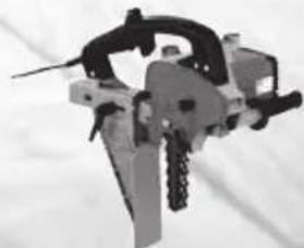
natural_image
Close-up of a mechanical tool or device with no visible text or symbolsLS 103 EcZK 115 EcLO
| GARANTIEGegen Vorlage der Garantieunterlage (Original-Kaufbeleg) werden innerhalb der jeweils gültigen Gewährleistungsregelungen kostenlos alle Reparaturen ausgeführt, die nach unseren Feststellungen wegen Material-, Bearbeitungs- und Montagefehlern erforderlich sind. Verbrauchs- und Verschleißteile sind hiervon ausgeschlossen. Hierzu muss die Maschine bzw. das Gerät frachtfrei an das Werk oder an eine MAFELL-Kundendienststelle geschickt werden. Vermeiden Sie, die Reparatur selbst zu versuchen, da dadurch der Garantieanspruch erlischt. Für Schäden, die durch unsachgemäße Behandlung oder durch normalen Verschleiß entstanden sind, wird keine Haftung übernommen. |
| WARRANTYUpon presentation of the warranty document (original invoice), we will carry out all repairs free of charge in accordance with the applicable warranty provisions, processing and mounting faults free of charge on presentation of this properly filled-in Guarantee Certificate and your original receipt. This is not valid for consumables and wearing parts. For this purpose, the machine or the appliance is to be forwarded freight paid to our plant or to an authorized MAFELL repair service. Refrain from trying to carry out the repairs yourself as otherwise your warranty claim will become extinct. We do not accept any liability for any damage resulting from improper handling or normal wear. |
| GARANTIESur présentation de cette carte de garantie, duement remplie par votre fournisseur et accompagnée de l'original de la pièce justifiant l'achat, nous effectuerons gratuitement toutes les réparations faisant l'objet d'un recours en garantie pendant la période indiquée, de la construction ou de la fabrication, à l'exclusion des pièces de consommation et d'usure. La machine ou l'appareil doit être pour cela expédié franco de port à notre usine ou à un atelier de service après-vente MAFELL. Évitez de procéder vous-mêmes à toute réparation, ceci périmant tout recours en garantie par la suite. Nous déclinons toute responsabilité en cas de dommages découlant d'une manipulation non conforme ou d'une usure normale. |
| GARANZIADietro presentazione del presente certificato di garanzia, regolarmente compilato, insieme alla ricevuta originale, vengono eseguite gratuitamente tutte le riparazioni necessarie riscontrate dai nostri accertamenti, entro il periodo di garanzia vigente, dovuti a difetti di materiale, di lavor azione o di montaggio. Da ciò sono esclusi pezzi di consumo e pezzi soggetti ad usura. A questo scopo la macchina ovvero l'apparecchio (eletrico) va spedito franco di porto allo stabilimento oppur e a d un punto di assistenza clienti della MAFELL. Evitate di tentare Voi stessi di effettuare la riparazione, altrimenti il diritto di garanzia viene revocato. Non ci assumiamo alcuna responsabilità per danni derivanti da trattamento non conforme o da normale usura. |
| GARANTIETegen vertoon van dit reglementair ingevuld garantie-bewijs, samen met het originele koopbewijs worden binnen de telkens geldige garantieregelingen gratis alle reparaties uitgevoerd, die volgens onzeconstateringen op grond van materiaal-, bewerkings- en montagefouten vereist zijn. Verbruik- en slijtagedelen zijn hiervan uitgesloten. Hiervoor moet de machine resp. het apparaat vrachtvrij naar de fabriek of naar een MAFELL-klantenservice worden gestuurd. Vermijdt u het de reparatie zelf uit te voeren, omdat daardoor de garantieclaim vervalt. Voor schade die door ondeskundige behandeling of door normale slijtage is ontstaan, wordt geen aansprakelijkheid aanvaardt. |
| GARANTÍAPresentando este documento de garantía (recibo original de compra), todas las reparaciones necesarias por defectos de material, errores de mecanizado o faltas de montaje en el marco de las reglamentaciones de la garantía concedida por parte del fabricante se efectuarán libre de gastos. Se excluyen sin embargo piezas fungibles o de desgaste. Para ello, entregue a porte pagado la máquina o el equipo a las fábricas del fabricante o a uno de los puntos de asistencia técnica de MAFELL. No realice nunca las tareas de reparación a cuenta propia. De lo contrario, caducará el derecho a garantía. No se asumirá responsabilidad alguna por los daños que se desprendan del uso inapropiado ni por el desgaste en el uso diario. |
| TAKUUTäta takuukuittia (alkuperäinen ostokuitti) vastaan suoritetaan voimassa olevan takuuajan sisällä maksutta kaikki korjaukset, jotka olemme todenneet tarpeellisiksi materiaali-, valmistus- ja asennusvirheistä johtuen. Käyttö- ja kuluvat osat ei kuulu takuupiriin. Korjausta varten kone tai laite on lähetettävä asianmukaisesti postitettuna joko tehtaalle tai johonkin MAFELL-asiakaspalveluun. Älä yritä korjata konetta itse, koska siinä tapauksessa takuu sammuu. Takuu ei vastaa vahingoista, jotka johtuvat asiaankuulumattomasta käytöstä tai normaalista kulumisesta. |
| GARANTIMot uppvisande av kvitto utförs kostnadsfritt, under giltiga garantiátaganden, alla reparationer som efter fastställande från vår sida kan härledas till material-, bearbetnings- eller monteringsfel. Förbruknings- och förslitningsdelar undantagna. Maskinen eller verktyget måste skickas fraktfritt till fabrik eller till MAFELLkundservice. Undvik att själv försöka utföra reparationen då detta leder till att garantianspråk förfaller. För skador som uppkommer på grund av felaktig behandling eller normalt slitage övertas inget ansvar. |
| GARANTIMod fremlæggelse af garantibeviset (original kvittering) ydes der gratis reparation af materiale-, fremstillings- og monteringsfejl, i henhold til de gældende garantibetingelser. Forbrugs- og sliddele udelukkes fra denne garanti. Hertil sendes maskinen/apparatet fragtfrit til producenten eller et Mafell-kundeserviceværksted. Hvis kunden selv forsøger at reparere maskinen, bortfalder garantien. Der overtages intet ansvar for beskadigelser, der opstår pga. uhensigtsmæssig brug eller normal slitage. |

MAFELL AG
Beffendorfer Straße 4, D-78727 Oberndorf / Neckar, Telefon +49 (0)7423/812-0
Fax +49 (0)7423/812-218 Internet: www.mafell.de E-Mail: mafell@mafell.de
- WARNUNG
- AVERTISSEMENT
- GB - EC Declaration of Conformity
- Inhaltsverzeichnis
- Signs and symbols
- Product information
- Manufacturer's data
- Machine identification
- Emissions
- Noise emission specifications
- Vibration specifications
- DDF 40 MaxiMAX
- Safety devices
- Danger
- Use according to intended purpose
- Residual risks
- Safety instructions
- General instructions:
- Do not use:
- Machine-specific safety instructions:
- Instructions on the use of personal protective equipment:
- Instructions on operation:
- Instructions on service and maintenance:
- Setting / Adjustment
- Mains connection
- Chip extraction
- Selection of tools
- Tool change
- Tilt adjustment
- Drill depth adjustment
- Height adjustment of tilting stop
- Operation
- Initial operation
- Switching on and off
- Drilling
- Drilling with stop pin (Fig. 16)
- Drilling with positioning on side faces (Fig. 17)
- Drilling according to tracing via base plate
- Drilling according to tracing via tilting stop
- Vertical drilling with tilting stop
- Vertical drilling with fixed distance 9.5 mm
- Drilling with additional stop set ZAG (Fig. 18-25)
- Drilling with position indicator PAZ according to tracing (drilling of longitudinal parts, e.g. drilling of frames)
- Drilling with lateral stop set SA 320
- Lateral stop for large edge distances and repositioning (flush body machining).
- Lateral stop for edge distance with infinitely variable fine adjustment (offset body machining)
- Lateral stop for producing rows of holes
- Drilling with trim stop LA (Fig. 24 + 25)
- Drilling with dowel drilling template
- Service and maintenance
- Storage
- Troubleshooting
- Optional accessories
- Exploded drawing and spare parts list
- Sommaire
Brand : Mafell
Model : DDF40
Category : Drill