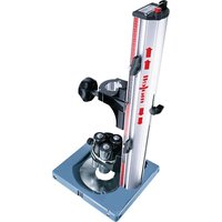
BST 320 - Drill Mafell - Free user manual and instructions
Find the device manual for free BST 320 Mafell in PDF.


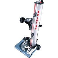
| Product Type | Drilling Station |
| Brand | Mafell |
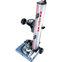
| Model | BST 320 |
| Max tool diameter at 0° | 130 mm |
| Max drilling length | 320 mm |
| Max drilling depth | 160 mm |
| Clamping range of centering sleeve | 8 – 30 mm |
| Tilt range | Non-tiltable (fixed 0°) |
| Weight | 45.1 kg |
| Power supply | via compatible drill (clamp Ø 43 mm) |
| Intended use | Drilling of wood and similar materials |
| Main functions | Vertical drilling, blind holes, depth adjustment, progressive centering |
| Standard equipment | Drilling station, insertion plate, service tool, manual, safety instructions |
| Accessories (optional) | Parallel guide, copying ring, wood drill bits, cassette |
| Safety | Wear goggles, ear protection, dust mask; do not work without protection |
| Care and cleaning | Regular cleaning of guides with a vacuum cleaner, spray machine oil, store dry and frost-free |
| Spare parts and repairability | Original MAFELL parts, exploded diagram at www.mafell.com |
| General information | Manual available in several languages; article numbers 961216, 961215, 961211, 961210, 961225, 961226, 961227 or 961228 |
Frequently Asked Questions - BST 320 Mafell
User questions about BST 320 Mafell
0 question about this device. Answer the ones you know or ask your own.
Ask a new question about this device
Download the instructions for your Drill in PDF format for free! Find your manual BST 320 - Mafell and take your electronic device back in hand. On this page are published all the documents necessary for the use of your device. BST 320 by Mafell.
USER MANUAL BST 320 Mafell
Drilling Station Translation of the original operating instructions 12
Please read all safety instructions and directions. Failure to comply with the safety instructions and directions can cause electric shock, fire and/or serious injuries. Please retain all safety instructions and directions for future reference.
AVERTISSEMENT
1 Signs and symbols 13
2 Product information 13
2.1 Manufacturer's data 13
2.2 Device identification 13
2.3 Technical data 13
2.4 Scope of supply 14
2.5 Use according to intended purpose 14
2.6 Residual risks 14
3 Safety instructions 14
4 Setting/Adjustment 15
4.1 Securing the drilling machine 15
4.2 Setting the drill guide 15
4.3 Tool change 15
4.4 Mounting the insert plate 15
4.5 Hoisting rope setting 15
4.6 Set 0^ angle (only BST 650 S and BST 460 S) 16
4.7 Mounting the copy insert (special accessory) 16
4.8 Working with the parallel guide (special accessory) 16
5 Operation 16
5.1 Initial operation 16
5.2 Operating method 16
5.3 Drill holes at right angles 16
5.4 Slanted drill holes (only BST 650 S and BST 460 S) 16
5.5 Stud holes 16
6 Service and maintenance 16
6.1 Unit 17
6.2 Storage 17
7 Troubleshooting 17
8 Optional accessories 17
9 Exploded drawing and spare parts list 19
1 Signs and symbols

This symbol appears at places where you will find instructions for your own safety.
Non-compliance with these instructions may result in very serious injuries.
This symbol indicates a potentially hazardous situation.
If this situation is not avoided, the product or objects in its vicinity may get damaged.

This symbol indicates tips for the user and other useful information.
2 Product information
for all units with the item numbers 961216, 961215, 961211, 961210, 961225, 961226, 961227 and 961228
2.1 Manufacturer's data
MAFELL AG, Beffendorfer Straße 4, D-78727 Oberndorf / Neckar, Phone +49 (0)7423/812-0, Fax +49 (0)7423/812-218
2.2 Device identification
All details required for machine identification are available on the attached rating plate

To reduce the risk of injury, please read the operating instructions.
2.3 Technical data
| BST 650 S | BST 460 S | BST 460 | BST 320 | |
| max. tool Ø at 0° | 130 mm | 130 mm | 130 mm | 130 mm |
| (5 1/8 in.) | (5 1/8 in.) | (5 1/8 in.) | (5 1/8 in.) | |
| max. tool Ø at 45° | 100 mm | 100 mm | - | - |
| (3 15/16 in.) | (3 15/16 in.) | |||
| max. drilling length 650 mm | 460 mm | 460 mm | 320 mm | |
| (25 19/32 in.) | (18 7/64 in.) | (18 7/64 in.) | (12 19/32 in.) | |
| max. drilling depth 455 mm | 265 mm | 300 mm | 160 mm | |
| (17 29/32 in.) | (10 7/16 in.) | (11 13/16 in.) | (6 19/64 in.) | |
| Clamping range drill guide | 8 - 30 mm | 8 - 30 mm | 8 - 30 mm | 8 - 30 mm |
| (5/16 - 1 3/16 | (5/16 - 1 3/16 | (5/16 - 1 3/16 | (5/16 - 1 3/16 | |
| in.) | in.) | in.) | in.) | |
| Swivel range on both sides | 45° | 45° | - | - |
| Weight 6,2 kg | 5,6 kg | 5,2 kg | 5,1 kg | |
| (13.7 lbs.) | (12.3 lbs.) | (11.5 lbs.) | (11.2 lbs.) |
2.4 Scope of supply
Drilling station BST 650 S, BST 460 S, BST 460 or BST 320 complete with:
1 insert panel
1 service tool in bracket on the machine
1 operating manual
1 folder "Safety Instructions"
2.5 Use according to intended purpose
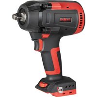
The drilling station is an all-purpose unit for drilling into wood and wood-like materials. It is used along with a suitable drill with a collar of 43 mm .
e.g. MAFELL Type HSB
Any other use than described above is not permissible. The manufacturer cannot be held liable for any damage arising from such other use.
In order to use the appliance as intended, you must comply with the operating, maintenance and repair instructions specified by MAFELL.
2.6 Residual risks

Danger
Even if used in accordance with its intended purpose and despite conforming with the safety instructions, residual risks caused by the intended use will always remain.
- Touching the drill bit while drilling
- Drill bit breaks
- Hearing impairment due to working without ear protection for longer periods of time
- Emission of hazardous wood dust when operated in closed areas with insufficient ventilation for longer periods of time.
3 Safety instructions

Danger
Always observe the following safety instructions and the safety regulations applicable in the respective country of use!
General instructions:
- Never work without the protection devices prescribed for the respective operating sequence and do not make any changes to the device that could impair safety.
- Children and adolescents may not operate this device. This rule does not apply to young persons receiving training and being supervised by an expert.
- Consider environmental influences. Do not expose the device to rain and avoid working near combustible liquids or gases.
- Chips or slivers must not be removed while the machine is in operation.
- Store the device in a dry, locked place outside the reach of children.
Instructions on the use of personal protective equipment:
- Always wear ear protectors during work.
- Always wear protective goggles during work.
- Always where a dust mark during work.
Instructions on operation:
- Provide for an unobstructed and slip-proof location with adequate lighting.
- Check to ensure that the tool is clamped correctly before switching it on.
- As far as possible ensure that the workpiece is secured from slipping away and toppling by using e.g. tension clamps.
- Ensure that the area where the drill bit emerges from the workpiece is free of obstacles.
- Examine the workpiece for foreign objects.
-
Never reach under the workpiece while working (risk of injury!).
-
Check the unit before every use. If damaged, do not use the unit. Only expert personnel may carry out repairs. Never open the unit yourself.
- When drilling adjust the feed to the drill bit and material thickness. Too large of a feed leads to motor overload, unclean drill holes and an accelerated blunting of the drill bit.
- Never take hold of the tool while the machine is in operation.
Instructions on service and maintenance:
- To ensure safety it is essential to regularly clean the unit, above all the guides. The drill must be removed from the unit before starting this work.
- Only original MAFELL spare parts and accessories may be used. Otherwise, the manufacturer will not accept any warranty claims and cannot be held liable.
4 Setting / Adjustment
4.1 Securing the drilling machine
Place a suitable drill with drill bit into the locating hole and clamp the machine with the handle 1 (Fig. 1).

Danger
Follow the safety instructions for the drill!
4.2 Setting the drill guide

The drill guide is continuously variable for drill bits between 0 8 mm and 0 30 mm.
Unfasten the wing nut 3 (Fig. 1) Use the wing nut to turn the setting disc so that the guide sleeves barely touch the drill bit circumference. Tighten the wing nut again.

The height of the drill guide can be adjusted along the column.
To do this unfasten both cylinder screws, 2 (Fig. 1) move the drill guides into the desired position and tighten the cylinder screws again.

The drill guide can be removed from the column for machining tools larger than 0.30mm .
To do this unfastern both cylinder screws 2 (Fig.1) until the drill guide can be removed.
In order to re-attach the drill guide, put it in place on the column and tighten the cylinder screws.
4.3 Tool change

Danger
Always remove the drill's power plug from the power supply before changing tools.
Completely open the drill guide (see section 4.2), open the boring socket of the drill and remove the tool.
Place the new tool into the drill and set the drill guide (see section 4.2).
4.4 Mounting the insert plate

Using the insert panel is recommended for drilling into end-grain wood or wood with thin widths.
Set the insert panel from below into the base plate and tighten it with both countersink screws 12 (Fig. 3).
4.5 Hoisting rope setting

Danger
The hoisting rope can be tensioned. The rope guide can be catapulted.

The returning force of the hoisting rope is continuously adjustable, which is especially advantageous for horizontal drill holes.
Open the tension lever 10 (Fig. 2) and move the rope guide to 9 to the desired position.
Re-tighten the tension lever.
4.6 Set 0^ angle (only BST 650 S and BST 460 S)
Unfasten the handle 8 (Fig. 2) by turning it. Press the button 11 and keep it pressed. Swivel the column slowly toward the 0^ angle (angle scale) until the push rod snaps into place. Turn the button to the left and then release it. Tighten the handle.
The 0^ angle is then locked into place. In order to release the lock, press the button downward and turn it toward the right until the push rode snaps out of place.
4.7 Mounting the copy insert (special accessory)

A copy insert (special accessory) can be used for hole patterns and rows of holes.

Templates with 25mm of wood or metal can be used for drilling the holes of repeated drilling patterns.
Set the copy insert from below into the base plate and tighten it with both countersink screws 12 (Fig. 3).
4.8 Working with the parallel guide (special accessory)
The parallel guide (special accessory) can be attached on all four sides to the base plate and be tightened with the wing nuts included in delivery.
The base plate has read-off edges on three sides; you can use them to read the scale on the parallel guide.
Furthermore the parallel guide can be used as a twin pad simply by turning it over.
The parallel guide also has a lateral stop that can be inserted into the side-face from both sides and then tightened with the Allen wrench included in delivery.
The scale can be read on the edges at the end of the side-face.
5 Operation
5.1 Initial operation
Personnel entrusted to work with the machine must be made aware of the operating instructions, calling particular attention to the chapter "Safety instructions".
Ensure that the tool is properly fastened.
5.2 Operating method
Switch on the drill.
Use moderate pressure to press the running drill downward until the crest of the drill thread engages the wood. The drill then automatically continues the feed. Once a hole has been drilled, the built-in Zugseilden Schlitten wieder zusück. It might be necessary to help by pulling on the handle of the drill.
The return force of the hoisting rope is continuously adjustable (see section 4.5).
5.3 Drill holes at right angles
First set the column to the ^ 0 angle (only BST 650 S and BST 460 S)
(see section 4.6)
Align the drilling station to the break of the desired bore hole. The break indicator on the base plate or insert panel are helpful for this.
5.4 Slanted drill holes (only BST 650 S and BST 460 S)

The column can be swivelled to the left and right by 45 degrees.
The pivot axis is on the workpiece surface so that the break indicator of the base plate can be used even when swivelled.
Unfasten the handle 8 (Fig. 2) by turning it. Swivel the column to the desired position accordinf to the angle scale 7. Re-tighten the handle.
5.5 Stud holes
Unfasten the tension lever 4 (Fig. 1). Set the depth stop 5 according to the depth scale 6 and re-tighten the tension lever. (Take the drill bit distance above the wood into account).
The surfaces of the depth stop marked in red and the die coloured depth scale are helpful for this.
6 Service and maintenance

Danger
Always remove the drill from the drilling station before working on the unit.

After a significant operating time MAFELL recommends that the unit be inspected by an authorised MAFELL customer service repair shop.
6.1 Unit
The unit must be regularly dusted. The guides should be cleaned with a vacuum cleaner.
Occasional spraying with machine oil maintains the ease of movement of joints and guide pieces.
The storage place must be dry and frost-protected. If the device fails despite diligent manufacturing and test procedures, the repair must be carried out by an
authorised customer service station for MAFELL products.

Danger
Only use MAFELL accessories and spare parts. Components of which their replacement has not been described must be replaced by a MAFELL customer service repair shop.
6.2 Storage
If the unit is not used for a long period of time, it must be cleaned carefully (see Chapter 6.1). Spray bright metal panels with a rust inhibitor.
7 Troubleshooting

Danger
Determining the causes for existing defects and eliminating these always requires increased attention and caution. Pull the mains plug beforehand!
Some of the most frequent defects and their causes are listed in the following chart. In case of other defects, contact your dealer or the MAFELL customer service.
| Defect Cause Elimination | ||
| Drill bit is stuck | Blunt drill bit | Replace or re-sharpen drill bit |
| Drill bit becomes very hot near the drill guide | Drill guide lies too taut on the drill bit | Rest the drill guide only lightly adjacent to the drill bit |
| The column cannot be sufficiently tightened after swivelling (only BST 650 S and BST 460 S) | Column clamp improperly set | Adjust the hex nut of the column clamp |
8 Optional accessories
- Parallel guide fence cpl.
- Template guide 24,8/18
- Template drill 025
-Drilling machine retaine 057
Order No. 204407
Order No. 204290
Order No. 090276
Order No. 204476
BST 650 S
- Drill box 650 with wood drill 12, 14, 16, 18, 20mm
Wood drill 10× 650
Wood drill 12 x 650 - Wood drill 14x 650
- Wood drill 16 x 650
- Wood drill 18 x 650
Wood drill 20 x 650
Wood drill 22 x 650
Wood drill 24 x 650 - Wood drill 26 x 650
Wood drill 28 x 650
Wood drill 30 x 650
BST 460 S / BST 460
- Drill box 460 with wood drill 8, 10, 12, 14, 16, 18mm
Wood drill 8 x 460
Wood drill 10 x 460
Wood drill 12 x 460 - Wood drill 14 x 460
Wood drill 16 x 460
Wood drill 18 x 460
Wood drill 20 x 460
Wood drill 22 x 460
Wood drill 24 x 460
Wood drill 26 x 460
Wood drill 28 x 460
Wood drill 30 x 460
Order No. 093292
Order No. 090240
Order No. 090241
Order No. 090242
Order No. 090243
Order No. 090244
Order No. 090245
Order No. 090246
Order No. 090247
Order No. 090248
Order No. 090249
Order No. 090250
Order No. 093291
Order No. 090251
Order No. 090252
Order No. 090253
Order No. 090254
Order No. 090255
Order No. 090256
Order No. 090257
Order No. 090258
Order No. 090259
Order No. 090260
Order No. 090261
Order No. 090262
BST 320
- Drill box 320 with wood drill Ø 8, 10, 12, 14, 16, 18 mm Order No. 093290
- Wood drill 6 x 320 Order No. 090279
- Wood drill 07 x 320 Order No. 090280
- Wood drill Ø 8 x 320 Order No. 090263
- Wood drill 09 x 320 Order No. 090264
- Wood drill Ø 10 x 320 Order No. 090265
- Wood drill 12 x 320 Order No. 090266
- Wood drill Ø 14 x 320 Order No. 090267
- Wood drill Ø 16 x 320 Order No. 090268
- Wood drill Ø 18 x 320 Order No. 090269
- Wood drill Ø 20 x 320 Order No. 090270
- Wood drill Ø 22 x 320 Order No. 090271
- Wood drill Ø 24 x 320 Order No. 090272
- Wood drill Ø 26 x 320 Order No. 090273
- Wood drill Ø 28 x 320 Order No. 090274
- Wood drill Ø 30 x 320 Order No. 090275
9 Exploded drawing and spare parts list
The corresponding information in respect of spare parts can be found on our homepage: www.mafell.com
Sommaire
4 Forbereda/stalla in
4.1 Fixera borrmaskin
- AVERTISSEMENT
- Signs and symbols
- Product information
- Manufacturer's data
- Device identification
- Technical data
- Scope of supply
- Use according to intended purpose
- Residual risks
- Danger
- Safety instructions
- General instructions:
- Instructions on the use of personal protective equipment:
- Instructions on operation:
- Instructions on service and maintenance:
- Setting / Adjustment
- Securing the drilling machine
- Setting the drill guide
- Tool change
- Mounting the insert plate
- Hoisting rope setting
- Set 0° angle (only BST 650 S and BST 460 S)
- Mounting the copy insert (special accessory)
- Working with the parallel guide (special accessory)
- Operation
- Initial operation
- Operating method
- Drill holes at right angles
- Slanted drill holes (only BST 650 S and BST 460 S)
- Stud holes
- Service and maintenance
- Unit
- Storage
- Troubleshooting
- Optional accessories
- BST 650 S
- BST 460 S / BST 460
- BST 320
- Exploded drawing and spare parts list
- Sommaire
- Forbereda/stalla in
- Fixera borrmaskin
Brand : Mafell
Model : BST 320
Category : Drill