ZB 400 E - Drill Mafell - Free user manual and instructions
Find the device manual for free ZB 400 E Mafell in PDF.


| Product Type | Timber Drill |
| Brand | Mafell |
| Model | ZB 400 E |
| Drilling depth with centering sleeve | 350 mm |
| Drilling depth without centering sleeve | 380 mm |
| Tiltable up to | 45° |
| Recommended drill bit diameter | 10 – 30 mm |
| Drill bit length | 650 mm |
| Clamping collar | 63 mm |
| No-load speed | 340 – 1450 min⁻¹ |
| Gearbox | Two-speed |
| Electronic speed control | Load stabilized |
| Rotation | Right / Left |
| Weight (without cable) | 9.4 kg |
| Power consumption | 1200 W |
| Output power | 760 W |
| Voltage and frequency | 230 V~, 50 Hz |
| Motor | Universal, interference-suppressed |
| Sound level at workstation (no load) | 89 dB(A) |
| Sound level at workstation (under load) | 90 dB(A) |
| Typical hand-arm vibration | ≤ 2.5 m/s² |
| Insulation class | II (double insulation) |
| Standard equipment | Drilling stand, centering sleeve, wood drill bit ∅18 mm, MK2 adapter, instruction manual, safety instructions booklet |
| Authorized use | Drilling in solid wood with wood drill bits |
| Regular maintenance | Dust removal, cleaning of drill bits, dry storage |
Frequently Asked Questions - ZB 400 E Mafell
User questions about ZB 400 E Mafell
0 question about this device. Answer the ones you know or ask your own.
Ask a new question about this device
Download the instructions for your Drill in PDF format for free! Find your manual ZB 400 E - Mafell and take your electronic device back in hand. On this page are published all the documents necessary for the use of your device. ZB 400 E by Mafell.
USER MANUAL ZB 400 E Mafell
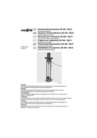
GB Carpentry Drilling Machine ZB 400 / 600 E Original operating instructions
natural_image
Mechanical testing device with helical rail and base mount (no visible text or symbols)ACHTUNG!
These operating instructions contain important notes on safe working practices with this machine. It is therefore essential that you read these operating instructions carefully!
AVERTISSEMENT !
EC Declaration of conformity 4
1 Product information.... 11
2 Safety instructions.... 13
3 Setting up / Adjusting.... 14
4 Operation 14
5 Service and maintenance.... 15
6 Troubleshooting 16
7 Optional accessories.... 16
8 Exploded drawing and spare parts list.... 16 Warranty.... 46
Table de matières

Figures.... 3
line
| Point | Time (min) | Value (mm) | |---|---|---| | A | 150 | 300 | | B | 200 | 400 | | C | 250 | 500 | | D | 300 | 600 | | E | 350 | 700 | | F | 400 | 800 | | G | 450 | 900 | | MAF00897 | 1500 | <20 | The chart displays a single line representing 'Time (min)' on the Y-axis against discrete X-axis points labeled A through G. The data points are marked with arrows, indicating direction of movement or measurement. The label '⑪' appears near point C, suggesting it corresponds to the specific data point in the plotted range.Abb. 4 (Fig. 4 ill. 4 afb. 4)
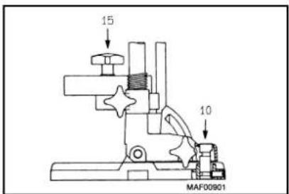
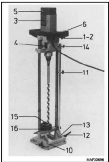
Abb. 3 (Fig. 3 ill. 3 afb. 3)
flowchart
graph TD
    A["Step 1"] --> B["Step 2"]
    B --> C["Step 3"]
    C --> D["Step 4"]
    D --> E["Step 5"]
    style A fill:#f9f,stroke:#333
    style B fill:#f9f,stroke:#333
    style C fill:#f9f,stroke:#333
    style D fill:#f9f,stroke:#333
    style E fill:#f9f,stroke:#333
Abb. 5 (Fig. 5 ill. 5 afb. 5)
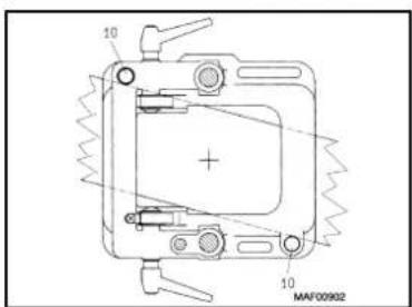
Abb. 7 (Fig. 7 ill. 7 afb. 7)Abb. 6 (Fig. 6 ill. 6 afb. 6)
GB - EC Declaration of Conformity
We herewith confirm that the machine ZB 400 E and ZB 600 E complies with the EU directives quoted. The standards listed were used for design and construction.
Empowered person for the configuration of the technical documents: Mafell AG
You will find the following warnings and symbols in these operating instructions:

This symbol indicates where you will find notes for your safety. If disregarded, this may result in very serious injuries.

This symbol indicates a potentially hazardous situation. If it is disregarded, the product or objects in its vicinity may be damaged.

This symbol indicates tips for the user and other useful information.
1 Product information
for machines with Art.-Nr. 922 901, 922 905 or 922 920 (ZB 400 E) 923 301 or 923 320 (ZB 600 E)
1.1 Manufacturer's data
MAFELL AG
P. O. Box 1180, D-78720 Oberndorf/Neckar
Phone +49 7423 812-0, Fax +49 7423 812-218
1.2 Machine identification
All data required for identification of the machine are stated on the rating plate which is attached to the motor casing.
1 Protection class II
CE-mark to declare conformity with the essential health and safety requirements according to Annex I of the Machinery Directive
Only for EU countries
Do not dispose of electric tools together with household waste material!
In observance of European Directive 2002/96/EC on waste electrical and electronic equipment and its implementation in accordance with national law, electric tools that have reached the end of their life must be collected separately and returned to an environmentally compatible recycling facility.
1.3 Technical data
Drilling depth with focussing device
( ZB 400 E 350 mm (13 25/32 in.)
( ZB 600 E 475 mm (18 45/64 in.)
( ZB 400 E 380 mm (14 31/32 in.)
( ZB 600 E 505 mm (19 7/8 in.)
Drilling depth without focussing device
Tiltable up to 45°
Drill bit diameter
( ZB 400 E 10 - 30 mm (25/64 - 1 3/16 in.)
( ZB 600 E 12 - 30 mm (15/32 - 1 3/16 in.)
Drill bit length
( ZB 400 E 650 mm (25 19/32 in.)
( ZB 600 E 820 mm (32 9/32 in.)
Clamping collar
63 mm (2 31/64 in.)
Drilling speed – no load 340 – 1450 rpm
- Two-stage mechanical gear
Electronic speed control stabilized under load
Clockwise / counterclockwise rotation
Weight without mains cable - with mount
( ZB 400 E 9,4 kg (20.7 lbs)
( ZB 600 E 9,4 kg (20.7 lbs)
Universal motor, radio and TV interference suppressed 230 V\~, 50 Hz
Power input (continuous operation) 1200 W
Power output 760 W
1.4 Noise emission
Noise emission values determined according to EN 60745-1 and 60745-2-1:
| Sound power level Workplace-related | emission value | |
| No load 100 dB (A) 89 dB (A) | ||
| Operation 101 dB (A) 90 dB (A) |
The noise measurement was recorded using the drill bit included in the standard equipment.
The stated values do not take any series variance into account and are not suitable for determining the immission sound power level, since this varies depending on the operating time, the machining operation concerned and environmental factors. The immission sound power level can consequently be determined only in the individual instance on the premises of the machine user.
1.5 Vibration
The typical hand-arm vibration is less than 2.5 m/s ^4 .
1.6 Delivery specification
Carpentry drilling machine ZB 400 E or ZB 600 E complete with:
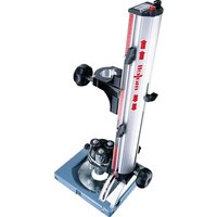
1 drill mount cpl.
1 focussing device
1 wood drill bit ∅ 18 mm (45/64 in.)
1 adaptor MK2, Art.-No. 039 139
1 operating manual
1 folder «Safety instructions»
1.7 Use according to intended purpose
The MAFELL carpentry drilling machine ZB 400 E / 600 E is intended exclusively for drilling of solid timber, using wood drill bits.
The length of the wood drill bits must be 650 mm (25 19/32 in.) for the ZB 400 E and 820 mm (32 9/32 in.) for the ZB 600 E. A drill bit diameter of 10 to 30 mm (25/64 to 1 3/16 in.) is recommended.
In conjunction with the special drill mount 039 160 (optional accessory) the carpentry drilling machine ZB 400 E / 600 E is intended for countersinking with ring-groove drilling tools and head countersinks, which are offered by MAFELL as optional accessories.
Any other use beyond this scope is considered as failing to comply with the intended purpose. The manufacturer is not liable for any damage caused as a result of this; the risk is borne solely by the user.
The machine is not suitable for operation in the rain outdoors or in areas subject to explosion hazards.
Use according to intended purpose also includes compliance with the operating, maintenance and repair conditions specified by MAFELL, and adherence to the safety instructions contained in the operating manual.
The carpentry drilling machine ZB 400 E / 600 may only be used, set up and serviced by persons over 18 years of age who are familiar with the machine and have been instructed as to the dangers involved. Repair work must be carried out by authorized MAFELL dealers or a MAFELL customer service station.
The safety regulations applicable in the country of use, as well as all other generally accepted rules on safety and occupational medicine, must be observed.
Unauthorized modifications to the machine preclude the liability of the manufacturer for any resultant damage.
1.8 Residual risks

Residual risks may also arise owing to the design of the machine relating to its intended purpose even if the machine is used properly and in compliance with all relevant safety regulations; e.g.:
- Touching the drill bit or the drill bit mounting when drilling.
Breakage of the drill bit. - Touching live parts with the housing open and the mains plug not removed.
- Hearing can be impaired when working for long periods without ear protectors.
Emission of wood dust: a health hazard when working for long periods without dust extraction.
2 Safety instructions

Woodworking machines can be dangerous when in use. You should therefore always follow the safety instructions set out in this chapter, as well as the safety regulations applicable in the country of use!
E General instructions:
Never work without the protective equipment prescribed for the relevant operation and do not make any modifications to the machine that could undermine safety.
Children and young persons must not operate this machine. This rule does not apply to young persons receiving training and being supervised by an expert.
Prior to all work, make sure that the safety and operating equipment is securely attached, undamaged and in good working condition.
Always be aware of environmental influences. Do not allow the machine to be exposed to the rain and do not use the machine in a damp or wet environment, or in the vicinity of inflammable liquids or gases.
When operating the machine outdoors, use of an earth-leakage circuit-breaker is recommended.
Do not carry the machine by the cable and do not remove the mains plug from the socket by pulling on the cable.
Protect the cable against oil and high temperatures and do not pull it over any sharp edges.
- Damaged cables or plugs must be renewed immediately.
- Avoid sharp bends in the cable. Especially when transporting and storing the machine, do not wind the cable around the machine.
- Only use wood drill bits with the technical data stated in this manual.
Do not use:
( damaged tools
( blunt tools
Store the machine in the dry under lock and key and out of reach of children.
Instructions on the use of personal safety equipment:
Always wear close-fitting industrial clothing and remove rings, bracelets and watches.
The sound pressure level at the workplace exceeds 85 dB (A). Users should therefore wear ear protectors.
Instructions on operation:
- Provide an uncluttered, anti-slip location with adequate illumination.
Before tool changes, making adjustments and eliminating malfunctions pull out the mains plug.
Never work with pieces which are too big or too small for the machine's capacity. - Thin, long drill bits (> 300 mm / 12 in.) at high speed should be used only with the focussing device.
- Machine must be switched off before being connected to the mains.
Before switching on, make sure that the drill bit is tightly secured and that the Allen key has been removed.
Whenever possible, secure the workpiece against slipping and tipping over (e. g. with screw clamps).
Do not begin drilling until the drill has reached full speed.
Examine the workpiece for foreign objects. Never attempt to drill into nails or other metal objects. - Keep your hands away from the underside of the workpiece when drilling (risk of injury!).
- When drilling, always lead the cable away from the machine to the rear.
Match the feed rate to the thickness of the workpiece when drilling. Excessive feedrates overload the motor, lead to poorly executed holes and blunt the drill bit prematurely.
Do not remove the machine from the workpiece until the drill bit is stationary.
Always keep your hands well away from the drill bit and the drill bit mounting while the machine is running.
The drilling machine must be operated only outdoors or on well ventilated premises as an effective chip and dust extraction is not possible.
Instructions on service and maintenance:
Regular cleaning of the machine, especially of the drill bit mounting, is an important safety factor. Before beginning this task, pull out the mains plug.
Only original MAFELL spare parts and accessories must be used. Otherwise the manufacturer does not offer any warranty and does not accept any liability.
3 Setting up / Adjusting
3.1 Mains connection

Machine must be switched off before being connected to the mains.
The carpentry drilling machine has Class II protective insulation (double-insulated).
Before starting up, make sure that the mains voltage matches the voltage stated on the rating plate.
3.2 Mounting and exchanging drill bits

Always pull out the mains plug before changing tools.
- Lift sleeve 7 (Fig. 1) until the ring groove 8 around the arbor becomes visible. Insert the drill bit into the arbor as far as it will go, the flat end of the drill bit should be in line with the two small grooves 9 cut into the end of the arbor. Release the sleeve.
- When using the focussing device the star knob 15 (Fig. 2) should be loosened so that the focussing disk 16 can be tilted. Insert the drill bit through the hole of the correct size, return the focussing disk to its normal position, insert the drill bit into the arbor as described above and tighten the star knob. Counter bore heads with ∅ of 80 and ∅ 100 mm (3 5/32 or 3 15/16 in.) should be used only in conjunction with the standard drill mount. For this purpose the upper (long) springs should be removed. Ringgroove drilling tools should be used only in conjunction with the special drill mount with stop plate, available as optional accessory.
- To exchange the drill bit hold it with one hand, lift sleeve 7 (Fig. 1) until the ring groove around the arbor becomes visible. Remove the drill bit and release the sleeve. Before inserting a new drill bit make sure that the shaft of the drill bit and the receiving, toolholding surface of the arbor are clean.
4 Operation

Do not switch on the machine if the drill bit is touching the workpiece.
4.1 Switching on and off
Temporary operation
- Switching on: Press switch 1 (Fig. 3).
- Switching off: Release switch.
Continuous operation
- Switching on: Press switch 1 first and then press locking button 2. The motor runs without keeping the switch pressed.
- Switching off: Press switch 1 until locking button 2 trips, then release the switch.
4.2 Adjusting drilling speed
This drilling machine has a gear box and an electronic speed control. The drilling speed can be adjusted continuously between 340 and 1450 rpm. The built-in electronics ensure a jerk-free acceleration when switching on and control the speed according to the value set.
The drilling speed required should be selected by referring to the diagramme 3 (Fig. 3) (see Fig. 4) and is set by means of the gear shift lever 4 (Fig. 3) and the setting wheel 5.

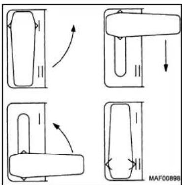
Gear should be shifted only when the motor has been switched off and the machine is running out or has stopped (see Fig. 5)! When the machine has been switched on the direction of rotation of the drill bit should be checked. If necessary, the direction of rotation can be changed by means of the reversing switch 6 (Fig. 3). Before actuating the reversing switch the motor should be switched off (the reversing switch is mechanically blocked).
4.3 Operating instructions
- Bolt 10 (Fig. 6) should be pushed down as far as possible.
- Place the machine in its correct position so that the drill bit will be exactly above the centre marking of the hole to be drilled. Turn the machine until the bolt touches the timber so that it can act as a stop for torsional force. When the machine has been switched on it should be pushed down with light pressure until the threaded tip of the drill bit has «taken» in the work. Now, the drill will advance automatically. If the drill bit should get stuck, the direction of rotation should be reversed. Before the reverse switch is actuated, the machine must be switched off.
To drill a blind pocket hole it is possible to set the drilling depth by means of the depth stop ring 11 (Fig. 3). To drill holes at an angle loosen clamping lever 12, tilt the machine until the angle desired is indicated on scale 13, tighten clamping lever again. When using short drill bits the maximum return stroke can be adapted by means of the depth stop ring 14.
To drill holes in the middle of a beam both bolts in the base plate of the drill mount should be pushed down and the machine should be turned until these bolts touch the beam on either side - max. width of a beam 22.5 cm (8 7/8 in.) (see Fig. 6 and Fig. 7).
For special work it may be necessary to use the stop plate which is available as optional accessory (Ref. No. 039 156).
4.4 Optional tools
The drilling machine can be used with ring-groove drilling tools and head countersinks. Special leaflets on request!
5 Service and maintenance

Pull out the mains plug before starting on any maintenance work!

MAFELL machines are designed to be low in maintenance. The ball bearings used are greased for life. After a prolonged period of operation, users are recommended to have the machine checked by an authorized MAFELL customer service shop.
5.1 Machine
The machine must be cleaned of dust deposits at regular intervals. When doing so, clean the air vents on the motor using a vacuum cleaner.
5.2 Tools
The drill bits used on the machine must be freed from resin regularly, as clean tools improve the drilling quality.
For cleaning only acid-free but no highly alkaline cleaning agents may be used.
This can be done by soaking the drill bits for 24 hours in paraffin or commercially available resin remover.
5.3 Storage
If the machine is out of service for a lengthy period of time, it should be thoroughly cleaned (see chapter
5.1). Spray bright metal panels with a rustproofing agent.
Store the machine only in dry rooms, where it is protected against weathering.
6 Troubleshooting

The determination of the causes of existing defects and their elimination always require increased attention and caution. Pull out the mains plug beforehand!
Some of the most frequent defects and their causes are listed in the following chart. In case of other defects, contact your dealer or the MAFELL customer service.
| Defect Cause Elimination | ||
| Machine cannot be switched on No mains voltage Check power supplyCarbon brushes worn Take the machine to a MAFELL customer service shop | ||
| Machine stops while drilling is in progress | Mains failure Check mains back-up fuse | |
| Drill bit jams | Blunt bit | Replace the drill bit or resharpen it |
7 Optional accessories
Stop plate, cpl. Ref. No. 039 156
Special drill mount Ref. No. 039 160
Supplementary handle, cpl. Ref. No. 039 203
Ejector drift 1 DIN 317 Ref. No. 093 001
8 Exploded drawing and spare parts list
The corresponding information in respect of spare parts can be found on our homepage: www.mafell.com
Français
natural_image
Close-up of a mechanical device with red and black components (no visible text or symbols)KSS 300 / KSS 400
natural_image
Illustration of a person riding a scooter with a curved ramp (no text or symbols)KSP 40 Flexistem
natural_image
Red and silver cleaning machine with visible blade and handle (no text or symbols)MT 55 cc
natural_image
Exterior view of a modern office building (no signage)MKS 130 Ec - MKS 185 Ec
natural_image
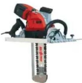
Close-up of a red and black power saw with chains attached (no visible text or symbols)ZSX Ec
natural_image
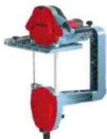
Mechanical device with red components and connecting rods (no visible text or symbols)Z 5 Ec
natural_image
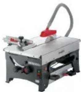
Industrial machine with handle and control panel (no visible text or symbols)ERIKA 60 E - ERIKA 85 Ec
natural_image
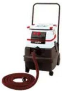
Exterior view of a portable industrial vacuum cleaner with red hose and control panel (no visible text or symbols)S 25 M / S 50 M
natural_image
Industrial cutting machine with red and silver components (no visible text or symbols)DD40 P / DD40 G
natural_image
Red and black power tool with base mount (no visible text or symbols)UVA 115 E
natural_image
Exterior view of a modern office building (no signage)MF 26 cc
natural_image
Industrial machine with handle and control panel (no visible text or symbols)ZH 205 Ec - ZH 320 Ec
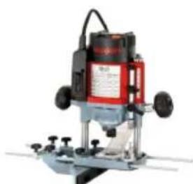
natural_image
Industrial milling machine with red and black components (no visible text or symbols)LO 65 Ec
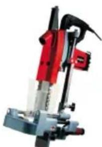
natural_image
Red and black industrial tool with mechanical base (no visible text or symbols)SKS 130
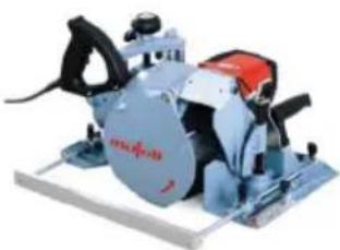
natural_image
Industrial machine with blue and red components mounted on a white base (no visible text or symbols)ZK 115 Ec
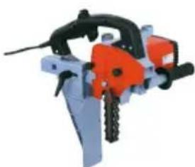
natural_image
Industrial cutting machine with orange and gray components (no visible text or symbols)LS 103 Ec
GARANTIE - WARRANTY - GARANZIA - GARANTÍA
Upon presentation of the warranty document (original invoice), we will carry out all repairs free of charge in accordance with the applicable warranty provisions, processing and mounting faults free of charge on presentation of this properly filled-in Guarantee Certificate and your original receipt. This is not valid for consumables and wearing parts. For this purpose, the machine or the electric tool is to be forwarded freight paid to our plant or to an authorized MAFELL repair service. Refrain from trying to carry out the repairs yourself as otherwise your warranty claim will become extinct. We do not accept any liability for any damage resulting from improper handling or normal wear.
- ACHTUNG!
- AVERTISSEMENT !
- Table de matières
- GB - EC Declaration of Conformity
- Product information
- Manufacturer's data
- Machine identification
- Technical data
- Noise emission
- Vibration
- Delivery specification
- Use according to intended purpose
- Residual risks
- Safety instructions
- E General instructions:
- Instructions on the use of personal safety equipment:
- Instructions on operation:
- Instructions on service and maintenance:
- Setting up / Adjusting
- Mains connection
- Mounting and exchanging drill bits
- Operation
- Switching on and off
- Temporary operation
- Continuous operation
- Adjusting drilling speed
- Operating instructions
- Optional tools
- Service and maintenance
- Machine
- Tools
- Storage
- Troubleshooting
- Optional accessories
- Exploded drawing and spare parts list
- Français
- GARANTIE - WARRANTY - GARANZIA - GARANTÍA
Brand : Mafell
Model : ZB 400 E
Category : Drill