ÉPIX Flex Drive - Lighting Chauvet - Free user manual and instructions
Find the device manual for free ÉPIX Flex Drive Chauvet in PDF.

| Product Type | Power Supply and Controller for ÉPIX Flex Series |
| Brand | Chauvet |
| Model | ÉPIX Flex Drive |
| Power Supply | 100-240 VAC, 50/60 Hz (universal) |
| Maximum Consumption | Up to 1920 LEDs (960 per port) |
| Control Protocols | DMX512, Art-Net™, sACN, RDM |
| Control Personalities | 17 channels, 34 channels, Pixel (720 channels per ÉPIX Flex 20) |
| Number of Output Ports | 2 ports (for ÉPIX Flex 20) |
| Maximum LEDs per Port | 960 (with ÉPIX Flex Boost) |
| Maximum Cable Length Between Drive and First Flex | 22.9 m (75 ft) |
| Maintenance and Cleaning | Disconnect before cleaning. Do not open. Use a dry cloth. |
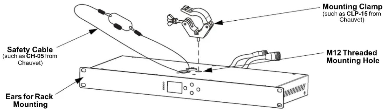
| Safety | Do not expose to water (IP20). Max ambient temperature 45°C. Mount with safety cable. Minimum distance 50 cm from surfaces. |
| Spare Parts and Repairability | Replaceable fuse (same type and rating). No user-serviceable components. |
| Warranty | Limited warranty (see Chauvet website for details). |
| Mounting | Rack mounting (brackets) or truss mounting (M12 threaded hole). |
| Display | LCD screen with configurable backlight. |
| Connections | DMX 5-pin, Ethernet (Art-Net/sACN), IEC power. |
Frequently Asked Questions - ÉPIX Flex Drive Chauvet
User questions about ÉPIX Flex Drive Chauvet
0 question about this device. Answer the ones you know or ask your own.
Ask a new question about this device
Download the instructions for your Lighting in PDF format for free! Find your manual ÉPIX Flex Drive - Chauvet and take your electronic device back in hand. On this page are published all the documents necessary for the use of your device. ÉPIX Flex Drive by Chauvet.
USER MANUAL ÉPIX Flex Drive Chauvet
natural_image
Line drawing of a rectangular electronic device with ports, connectors, and a central square component (no text or symbols)About This Guide
The ÉPIX Flex Drive Quick Reference Guide (QRG) has basic product information such as connection, mounting, menu options, and control values. Download the User Manual from www.chauvetprofessional.com for more details.
Disclaimer
The information and specifications contained in this QRG are subject to change without notice.
LIMITED WARRANTY
FOR WARRANTY REGISTRATION AND COMPLETE TERMS AND CONDITIONS PLEASE VISIT OUR WEBSITE.
For Customers in the United States and Mexico: www.chauvetlighting.com/warranty-registration.
For Customers in the United Kingdom, Republic of Ireland, Belgium, the Netherlands, Luxembourg, France, and Germany: www.chauvetlighting.eu/warranty-registration.
Chauvet warrants that this product shall be free from defects in material and workmanship under normal use, for the period specified in, and subject to the exclusions and limitations set forth in the full limited warranty on our website. This warranty extends only to the original purchaser of the product and is not transferable. To exercise rights under this warranty, you must provide proof of purchase in the form of an original sales receipt from an authorized dealer that shows the product name and date of purchase. THERE ARE NO OTHER EXPRESS OR IMPLIED WARRANTIES. This warranty gives you specific legal rights. You may also have other rights that vary from state to state and country to country. This warranty is valid only in the United States, United Kingdom, Republic of Ireland, Belgium, the Netherlands, Luxembourg, France, Germany and Mexico. For warranty terms in other countries, please consult your local distributor.
Safety Notes
These Safety Notes include important information about installation, use, and maintenance.
- DO NOT open this product. It contains no user-serviceable parts.
- DISCONNECT from power before cleaning or replacing the fuse.
- To eliminate unnecessary wear and improve its lifespan, during periods of non-use completely disconnect the product from power via breaker or by unplugging it.
- CAUTION: When transferring product from extreme temperature environments, (e.g. cold truck to warm humid ballroom) condensation may form on the internal electronics of the product. To avoid causing a failure, allow product to fully acclimate to the surrounding environment before connecting it to power.
- CAUTION: This product's housing may be hot when lights are operating.
• Mount this product in a location with adequate ventilation, at least 20 in (50 cm) from adjacent surfaces.
• DO NOT leave any flammable material within 50 cm of this product while operating or connected to power. - USE a safety cable when mounting this product overhead.
- DO NOT operate this product outdoors or in any location where dust, excessive heat, water, or humidity may affect it. (IP20)
- DO NOT operate this product if the housing, ports, or cables appear damaged.
- DO NOT connect this product to a dimmer or rheostat.
- Replace the fuse with one of the same type and rating.
- ONLY connect this product to a grounded and protected circuit.
- In the event of a serious operating problem, stop using immediately.
• The maximum ambient temperature is 113 °F (45 °C). Do not operate this product at higher temperatures.
Contact
Outside the U.S., U.K., Ireland, Benelux, France, Germany, or Mexico, contact your distributor to request support or return a product. Refer to Contact Us at the end of this QRG for contact information.
What is Included
- ÉPIX Flex Drive • Power Cord • Quick Reference Guide
AC Power
This product has an auto-ranging power supply that works with an input voltage range of 100 to 240 VAC, 50/60 Hz.
AC Plug
| Connection | Wire (U.S.) | Wire (Europe) | Screw Color |
| AC Live Black Brown Yellow/Brass | |||
| AC Neutral White Blue Silver | |||
| AC Ground Green/Yellow | Green/Yellow | Green |

To eliminate wear and improve its lifespan, during periods of non-use completely disconnect the product from power via breaker or by unplugging it.
Fuse Replacement
- Disconnect the product from power.
- Wedge the tip of a flat-head screwdriver into the slot of the fuse holder.
- Pry the safety cap out of the housing.
- Remove the blown fuse from the clip on the front of the safety cap and replace with a fuse of the exact same type and rating.
- Re-insert the fuse holder and reconnect power.
Signal Connections
The ÉPIX Flex Drive can link to a controller or controller software using an ethernet or 5-pin DMX connection. If using other Art-Net™, sACN, or DMX-compatible products with the ÉPIX Flex Drive, they can all be controlled individually on a single network. See the User Manual for information about how to connect and configure the product for these signals.
Control Personalities
The ÉPIX Flex Drive uses DMX, Art-Net™, and sACN for its control personalities:
| Personality Channels Description | ||
| 17 Channel 17 | Dimmer, foreground and background RGB control, strobe, auto programs, program speed, and offset, test mode | |
| 34 Channel 17 per output | Enables output ports to be addressed separately for individual 17-channel control | |
| Pixel 720 per ÉPIX Flex 20 | Complete pixel control. Only 170 LEDs are accessible by DMX. An ethernet protocol (Art-NetTM or sACN) with multiple universes must be used to access all connected LEDs. | |
Art-Net™ Connection
Art-Net™ is an Ethernet protocol that uses TCP/IP that transfers large amount of DMX512 data using an ethernet connection over a large network. An Art-Net™ protocol document is available from www.chauvetprofessional.com. Art-Net™ Designed by and Copyright Artistic Licence Holdings Ltd.
sACN Connection
Also known as ANSI E1.31, Streaming-ACN is an Ethernet protocol that uses the layering and formatting of Architecture for Control Networks to transport DMX512 data over IP or any other ACN compatible network.
DMX Connection
The ÉPIX Flex Drive will work with a DMX controller using a 5-pin DMX data connection. A DMX Primer is available from www.chauvetprofessional.com.
RDM (Remote Device Management)
Remote Device Management, or RDM, is a standard for allowing DMX-enabled devices to communicate bi-directionally along existing DMX cabling. The ÉPIX Flex Drive supports RDM protocol that allows feedback to make changes to menu map options. Download the User Manual from www.chauvetprofessional.com for more details.
The ÉPIX Flex Drive also supports RDM over Art-Net™.
Mounting
Before mounting this product, read the Safety Notes. Make sure the mounting clamp is capable of supporting the weight of the product. For our CHAUVET Professional line of mounting clamps, go to http://trusst.com/products.
Mounting Diagram
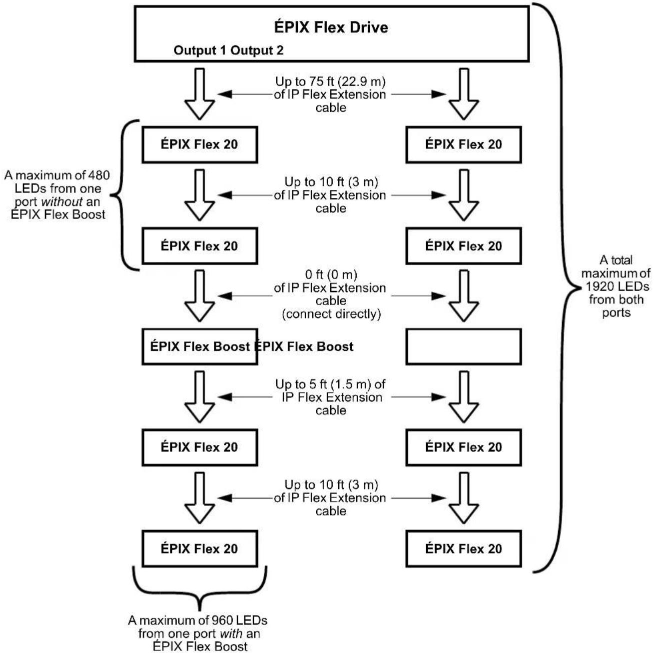
Connecting ÉPIX Flex Products
The ÉPIX Flex Drive is the power supply for the ÉPIX Flex series of products. Each product must be daisy-chained together in series. This power supply is capable of powering up to 1,920 LEDs (960 from each port).
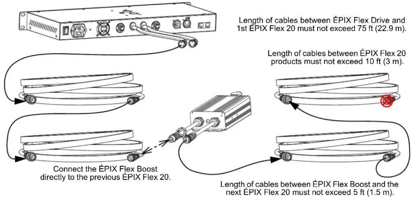
The ÉPIX Flex Drive can support 2 ÉPIX Flex 20 products with each port by itself, for a total of 4 ÉPIX Flex 20 products.
Connect an ÉPIX Flex Boost after the second ÉPIX Flex 20 product on each port to enable the ÉPIX Flex Drive to support an additional 2 ÉPIX Flex 20 products with each port. This increases the total to 8 ÉPIX Flex 20 products (4 per port).

The recommended connection order from each port of the EPIX Flex Drive is as follows:
-
EPIX Flex Drive port
-
ÉPIX Flex 20
-
ÉPIX Flex 20
-
ÉPIX Flex Boost
-
ÉPIX Flex 20
-
ÉPIX Flex 20 (end)
• Make sure the length of cables between each ÉPIX Flex Drive port and the first ÉPIX Flex 20 does not exceed 75 ft (22.9 m).

- Make sure the length of cables between each ÉPIX Flex 20 does not exceed 10 ft (3 m).
- Make sure the ÉPIX Flex Boost is plugged directly into the previous ÉPIX Flex 20.
- Make sure the length of cables between the ÉPIX Flex Boost and the next ÉPIX Flex 20 does not exceed 5 ft (1.5 m).

Use ONLY CHAUVET Professional cables with the ÉPIX Flex Drive. For our line of cables compatible with the ÉPIX Flex Drive, go to https://www.chauvetprofessional.com/accessories.
ÉPIX Flex Products Flowchart
flowchart
graph TD
    A["ÉPIX Flex Drive\nOutput 1 Output 2"] --> B["ÉPIX Flex 20"]
    A --> C["ÉPIX Flex 20"]
    B --> D["ÉPIX Flex 20"]
    C --> E["ÉPIX Flex 20"]
    D --> F["ÉPIX Flex Boost ÉPIX Flex Boost"]
    E --> G["ÉPIX Flex 20"]
    F --> H["ÉPIX Flex 20"]
    G --> I["ÉPIX Flex 20"]
    H --> J["ÉPIX Flex 20"]
    I --> K["ÉPIX Flex 20"]
    J --> L["ÉPIX Flex 20"]
    K --> M["ÉPIX Flex 20"]
    L --> N["ÉPIX Flex 20"]
    M --> O["A maximum of 960 LEDs\nfrom one port with an ÉPIX Flex Boost"]
    N --> P["A maximum of 480 LEDs from one port without an ÉPIX Flex Boost"]
    Q["Up to 75 ft (22.9 m)\nof IP Flex Extension\ncable"] --> R["ÉPIX Flex 20"]
    S["Up to 10 ft (3 m)\nof IP Flex Extension\ncable"] --> T["ÉPIX Flex 20"]
    U["0 ft (0 m)\nof IP Flex Extension\ncable\n(connect directly)"] --> V["ÉPIX Flex Boost ÉPIX Flex Boost"]
    W["Up to 5 ft (1.5 m)\nof IP Flex Extension\ncable"] --> X["ÉPIX Flex 20"]
    Y["Up to 10 ft (3 m)\nof IP Flex Extension\ncable"] --> Z["ÉPIX Flex 20"]
    AA["A total maximum of 1920 LEDs\nfrom both ports"] --> AB["ÉPIX Flex 20"]
    AC["A maximum of 960 LEDs\nfrom one port with an ÉPIX Flex Boost"] --> AD["ÉPIX Flex 20"]
Control Panel Description
| Button Function | |
| Exits from the current menu or function | |
| Navigates upwards through the menu list and increases the numeric value when in a function | |
| Navigates downwards through the menu list and decreases the numeric value when in a function | |
| Enables the currently displayed menu or sets the currently selected value into the selected function | |
Menu Map
Refer to the ÉPIX Flex Drive product page on www.chauvetprofessional.com for the latest menu map.
| Main Level Programming Levels Description | ||||
| 1.Operating Mode | 1.Standalone | Selects the control protocol | ||
| 2.Art-Net | ||||
| 3.sACN | ||||
| 4.DMX | ||||
| 2.Personality | 1.17 Channel | Sets the control personality (see Control Personalities)2.34 Channe | ||
| 3.Pixel | ||||
| 3.Port Setup | 1.Output 1 | 1.DMX Start Address | 1-496 Sets the starting address for Output 1 | |
| 2.Network Universe | 0-256 | Sets the lowest of the consecutive universes to which Output 1 is assigned (range determined by Operating Mode) | ||
| 3.LED Quantity | 1-960 Sets the number of LEDs controlled by Output 1 | |||
| 2.Output 2 | 1.DMX Start Address | 1-496 | Sets the starting address for Output 2 in 34 Channel mode and Pixel mode | |
| 2.Network Universe | 0-256 | Sets the lowest of the consecutive universes to which Output 2 is assigned (range determined by Operating Mode) | ||
| 3.LED Quantity | 1-960 Sets the number of LEDs controlled by Output 2 | |||
| 4.Set IP Mode | 1.Manual IP | _ _ _ _ _ _ _ _ _ _ _ _ _ _ _ _ _ _ _ _ _ _ _ _ _ _ _ _ _ _ _ _ _ _ _ _ _ _ _ _ _ _ _ _ _ _ _ _ _ _ _ _ _ _ _ _ _ _ _ _ _ _ _ _ _ _ _ _ _ _ _ _ _ _ _ _ _ _ _ _ _ _ _ _ _ _ _ _ _ _ _ _ _ _ _ _ _ _ _ _ _ | Sets a custom IP address (0-255) | |
| 2.Static IP Sets a preset IP | address | |||
| 5.Set Netmask | A. 255.000.000.000 | Sets the net maskB. 255.255.000.000 | ||
| C. 255.255.255.000 | ||||
| 6.Standalone Mode | 1.User Color | 1.Red: | 000-255 | Combine red, green, and blue to make a custom color |
| 2.Green: | ||||
| 3.Blue: | ||||
| 2.Preset Color | 1.Red | Preset static colors | ||
| 2.Green | ||||
| 3.Blue | ||||
| 4.Cyan | ||||
| 5.Magenta | ||||
| 6.Yellow | ||||
| 7.White | ||||
| 3.Automatic | 1.Program: 000-042 Selects an automatic program | |||
| 2.Speed: 000-100 Sets the automatic program speed | ||||
| 7.Set LCD Backlight | On | Display backlight always on | ||
| 30s | Turns off display backlight after 30 seconds of inactivity | |||
| 8.Set Display | Normal | Rotates display 180° | ||
| Inverted | ||||
| 9.Factory Reset | NO | Resets the product to factory defaults | ||
| YES | ||||
| 10.Fixture UID | _ _ _ _ _ _ _ _ _ _ _ _ _ _ _ _ _ _ _ _ _ _ _ _ _ _ _ _ _ _ _ _ _ _ _ _ _ _ _ _ _ _ _ _ _ _ _ _ _ _ _ _ _ _ _ _ _ _ _ _ _ _ _ _ _ _ _ _ _ _ _ _ _ _ _ _ _ _ _ _ _ _ _ _ _ _ _ _ _ _ _ _ _ _ _ _ _ _ | |||
| 11.Firmware Version | B_. V_. - . . . | Shows current firmware version | ||
Control Values
17 Channel/34 Channel
| Channel Function Value Percent/Setting | |||
| 1 | Master Dimmer | 000 ⇔ 255 | 0–100% |
| 2 | Foreground Red | 000 ⇔ 255 | 0–100% |
| 3 | Foreground Green | 000 ⇔ 255 | 0–100% |
| 4 | Foreground Blue | 000 ⇔ 255 | 0–100% |
| 5 Foreground Strobe | 000 ⇔ 010 No function | ||
| 011 ⇔ 050 | Strobe, slow to fast | ||
| 051 ⇔ 090 | Random strobe, slow to fast | ||
| 091 ⇔ 140 | Synchronized random strobe, slow to fast | ||
| 141 ⇔ 255 | Reserved for future use | ||
| 6 | Background Red | 000 ⇔ 255 | 0–100% |
| 7 | Background Green | 000 ⇔ 255 | 0–100% |
| 8 | Background Blue | 000 ⇔ 255 | 0–100% |
| 9 Background Strobe | 000 ⇔ 010 No function | ||
| 011 ⇔ 050 | Strobe, slow to fast | ||
| 051 ⇔ 090 | Random strobe, slow to fast | ||
| 091 ⇔ 140 | Synchronized random strobe, slow to fast | ||
| 141 ⇔ 255 | Reservedfor future use | ||
| 10 | Foreground Program | 000 | No function |
| 001 ⇔ 020 | Automatic program 0 | ||
| 021 ⇔ 040 | Automatic program 1 | ||
| 041 ⇔ 060 | Automatic program 2 | ||
| 061 ⇔ 065 | Automatic program 3 | ||
| 066 ⇔ 080 | Multi-color program | ||
| 081 ⇔ 100 | Color fade program 1 | ||
| 101 ⇔ 120 | Color fade program 2 | ||
| 121 ⇔ 140 | Color fade program 3 | ||
| 141 ⇔ 255 | Reserved for future use | ||
| 11 | Foreground Speed | 000 ⇔ 255 | Foreground program speed, slow to fast |
| 12 | Foreground Offset | 000 ⇔ 255 | Foreground program offset delay, short to long |
| 13 | Background Program | 000 | No function |
| 001 ⇔ 020 | Automatic program 0 | ||
| 021 ⇔ 040 | Automatic program 1 | ||
| 041 ⇔ 060 | Automatic program 2 | ||
| 061 ⇔ 065 | Automatic program 3 | ||
| 066 ⇔ 255 | Reserved for future use | ||
| 14 | Background Speed | 000 ⇔ 255 | Background program speed, slow to fast |
| 15 | Background Offset | 000 ⇔ 255 | Background program offset delay, short to long |
| 16 | No Function | 000 ⇔ 255 | No function |
| Channel Function Value Percent/Setting | |||
| 17 Test | Mode | 000 ⇔ 020 | No function |
| 021 ⇔ 030 | Test 1 (white) | ||
| 031 ⇔ 040 | Test 2 (color fade) | ||
| 041 ⇔ 050 | Test 3 (color scroll) | ||
| 051 ⇔ 060 | Test 4 (red) | ||
| 061 ⇔ 070 | Test 5 (green) | ||
| 071 ⇔ 080 | Test 6 (blue) | ||
| 081 ⇔ 255 | Reserved for future use | ||

• 34 Channel mode is identical to 17 Channel mode.
- In 17 Channel mode, Output 2 is addressed the same as Output 1.
- In 34 Channel mode, Output 2 can be addressed separately from Output 1.
Pixel
| Channel Function Value Percent/Setting | |||
| 1 | Red 1 | 000 ⇔ 255 | 0–100% |
| 2 | Green 1 | 000 ⇔ 255 | 0–100% |
| 3 | Blue 1 | 000 ⇔ 255 | 0–100% |
| 4 | Red 2 | 000 ⇔ 255 | 0–100% |
| 5 | Green 2 | 000 ⇔ 255 | 0–100% |
| 6 | Blue 2 | 000 ⇔ 255 | 0–100% |
| ... | ... | ... | ... |
| 505 | Red 169 | 000 ⇔ 255 | 0–100% |
| 506 | Green 169 | 000 ⇔ 255 | 0–100% |
| 507 | Blue 169 | 000 ⇔ 255 | 0–100% |
| 508 | Red 170 | 000 ⇔ 255 | 0–100% |
| 509 | Green 170 | 000 ⇔ 255 | 0–100% |
| 510 | Blue 170 | 000 ⇔ 255 | 0–100% |
| 511 | Red 171 | 000 ⇔ 255 | 0–100% (not accessible by DMX) |
| 512 | Green 171 | 000 ⇔ 255 | 0–100% (not accessible by DMX) |

- Only 170 LEDs are accessible by DMX in Pixel mode.
- An ethernet protocol (Art-Net™ or sACN) with multiple universes must be used to access all connected LEDs in Pixel mode.
Acerca de Esta Guía
17 Channel/34 Channel
RDM (Remote Device Management)
17 Channel/34 Channel
General Information Technical Support
Chauvet World Headquarters
Address: 5200 NW 108th Ave. Voice: (844) 393-7575
Sunrise, FL 33351 Fax: (954) 756-8015
Voice: (954) 577-4455 Email: chauvetcs@chauvetlighting.com
Fax: (954) 929-5560
Toll Free: (800) 762-1084 Website: www.chauvetprofessional.com
Chauvet Europe Ltd.
Address: Unit 1C Email: UKtech@chauvetlighting.eu
Brookhill Road Industrial Estate
Pinxton, Nottingham, UK Website: www.chauvetprofessional.eu
NG16 6NT
Voice: +44 (0) 1773 511115
Fax: +44 (0) 1773 511110
Chauvet Europe BVBA
Address: Stokstraat 18 Email: BNLtech@chauvetlighting.eu
9770 Kruishoutem
Belgium Website: www.chauvetprofessional.eu
Voice: +32 9 388 93 97
Chauvet France
Address: 3, Rue Ampère
91380 Chilly-Mazarin
Email: FRtech@chauvetlighting.fr
France Website: www.chauvetprofessional.eu
Voice: +33 1 78 85 33 59
Chauvet Germany
(Entrance by Calle 2)
Email: servicio@chauvet.com.mx
Zona Industrial Lerma Website: www.chauvetprofessional.mx
Visit the applicable website above to verify our contact information and instructions to request support. Outside the U.S., U.K., Ireland, Mexico, France, Germany, or Benelux, contact the dealer of record.

ETHERNET


MET E114016
Complies with
UL 8750
CSA C22.2 No. 250.13


RoHS