
CP Rack - Lighting Chauvet - Free user manual and instructions
Find the device manual for free CP Rack Chauvet in PDF.

| Product Type | Lighting Support |
| Brand | Chauvet |
| Model | CP Rack |
| Maximum Load Capacity | 450 kg |
| Adjustable Height | Yes, extendable H-frames |
| Stackable | Yes, up to 2 units |
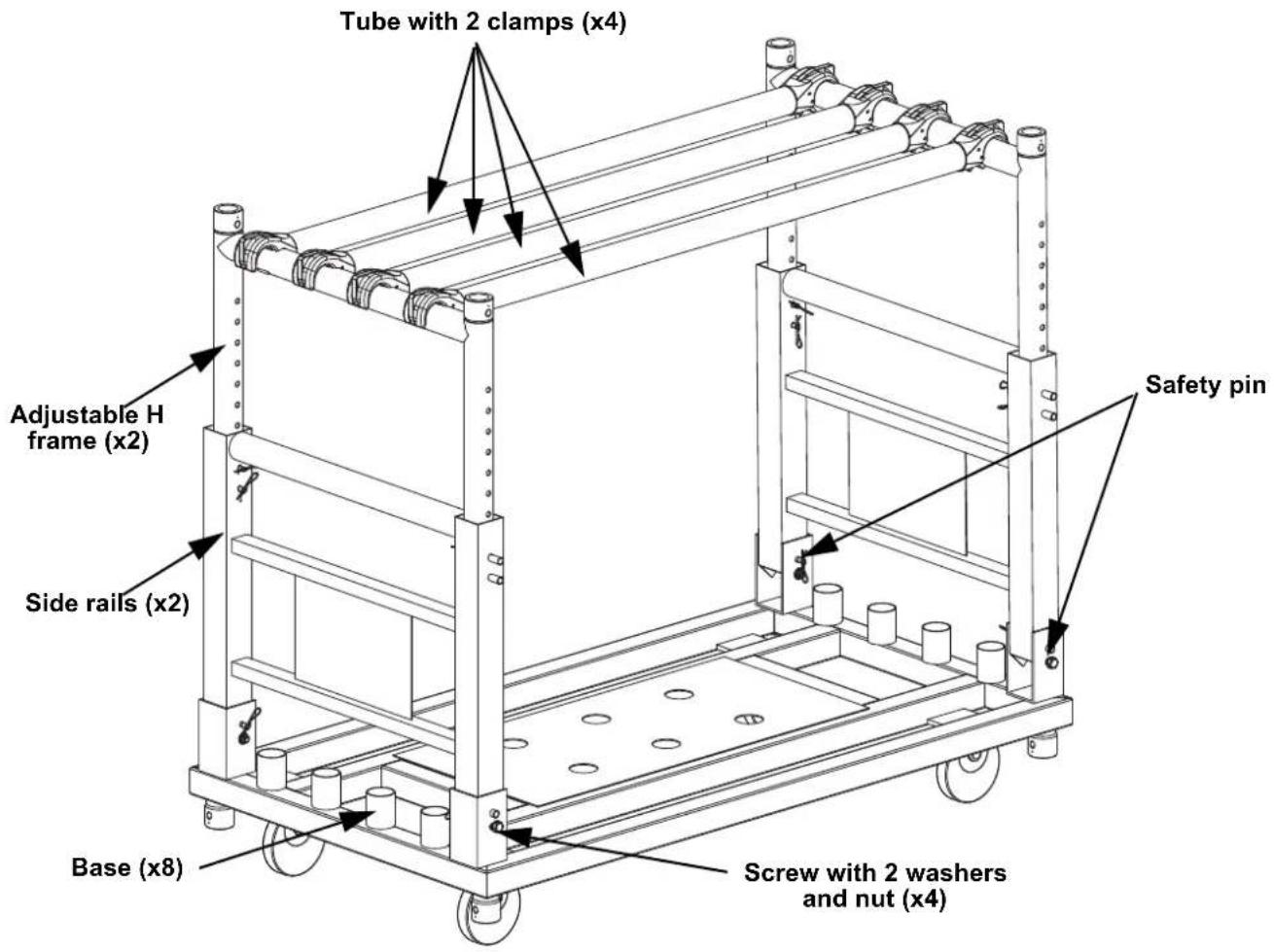
| Number of Tubes | 4 |
| Number of H-Frames | 2 |
| Number of Side Rails | 2 |
| Number of Bases | 8 |
| Included Accessories | Quick Reference Guide, cover |
| Type of Fastening | Cotter pins, safety clips |
| Intended Use | Support for projectors and lighting equipment |
| Environmental Conditions | Avoid extreme environments (marine/saline, temperatures outside range, flooding) |
| Safety Instructions | Included in the manual |
| Extension Possible | Extendable H-frames to double height |
| Swivel Clamps | Yes, for attaching tubes to H-frames |
Frequently Asked Questions - CP Rack Chauvet
User questions about CP Rack Chauvet
0 question about this device. Answer the ones you know or ask your own.
Ask a new question about this device
Download the instructions for your Lighting in PDF format for free! Find your manual CP Rack - Chauvet and take your electronic device back in hand. On this page are published all the documents necessary for the use of your device. CP Rack by Chauvet.
USER MANUAL CP Rack Chauvet
Scan the QR code to access the product page and warranty terms.
CP RACK
Quick Reference Guide
English EN
Español ES
Français FR
Deutsch DE
Nederlands NL
natural_image
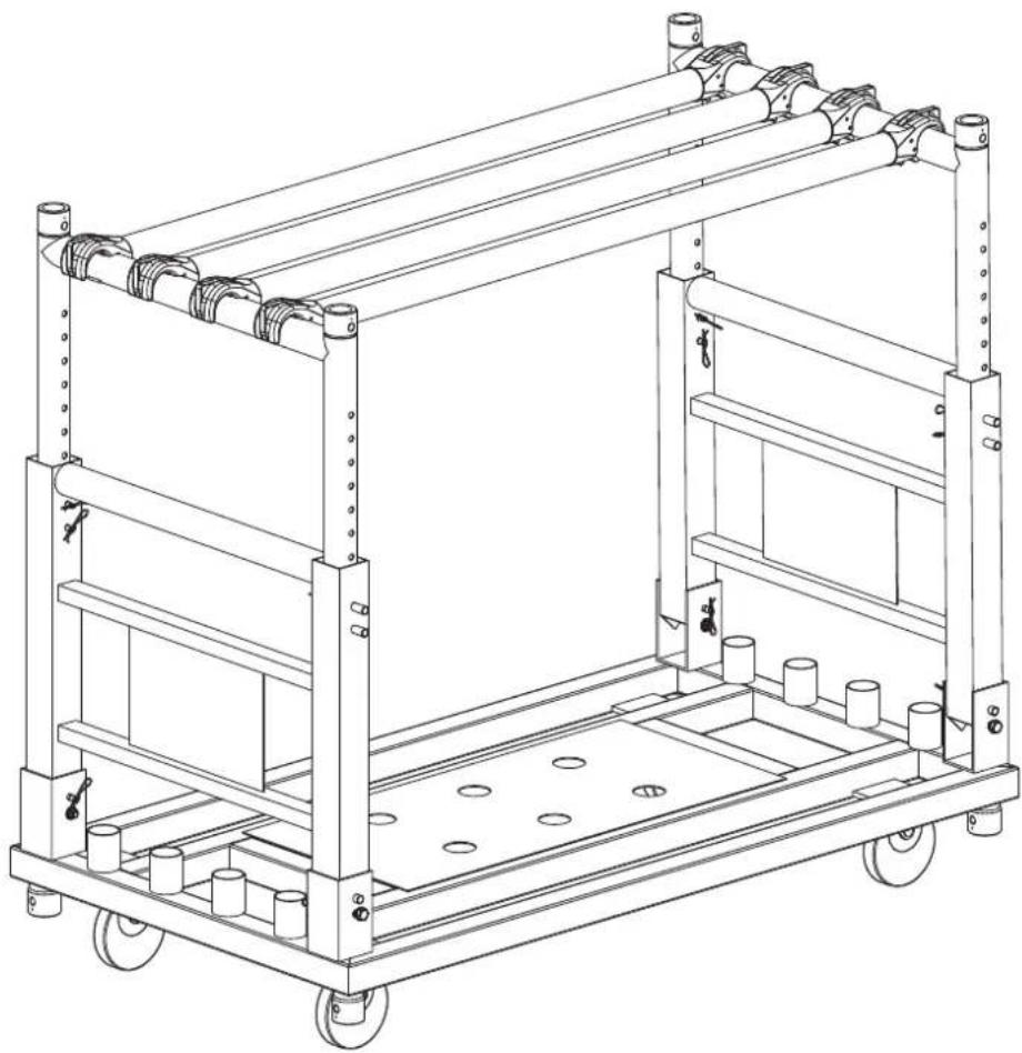
Technical line drawing of a multi-level industrial cart with wheels and structural supports (no text or symbols)Model ID: CPRACK
Intentionally Left Blank Page
Safety Notes
These Safety Notes include important information about installation, use, and maintenance of the CP Rack.
• D O N O T :

- Leave outdoors in locations with extreme environmental conditions. This includes, but is not limited to:
- Exposure to a marine/saline environment (within 3 miles of a saltwater body of water).
- Locations where normal temperatures exceed the temperature ranges in this manual.
- Locations that are prone to flooding or being buried in snow.
• Other areas where the product will be subject to extreme radiation or caustic substances.
- In the event of a serious operating problem, stop using immediately.
What is Included
• C P R a c k
- Cover
- Quick Reference Guide
Symbols
Symbol Meaning


Critical installation, configuration, or operation information. Not following these instructions may make the product not work, cause damage to the product, or cause harm to the operator.
Important installation or configuration information. The product may not function correctly if this information is not used.
Useful information.
Product Overview
Setup
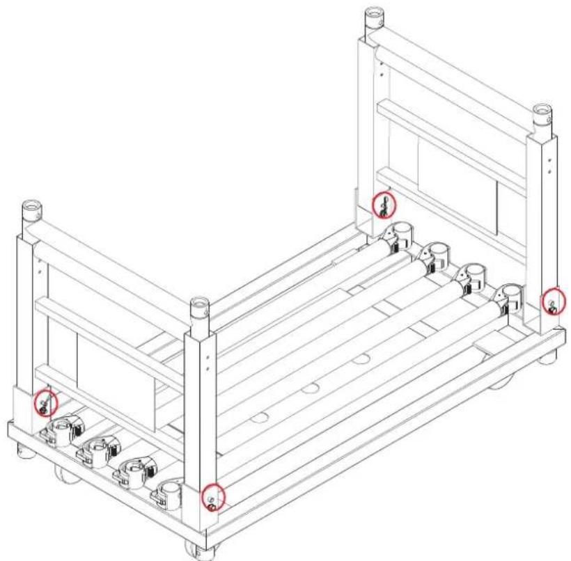
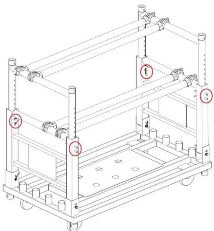
1. To begin setup:
a. Raise each side rail of the CP Rack by removing the pins at the base of each side rail.
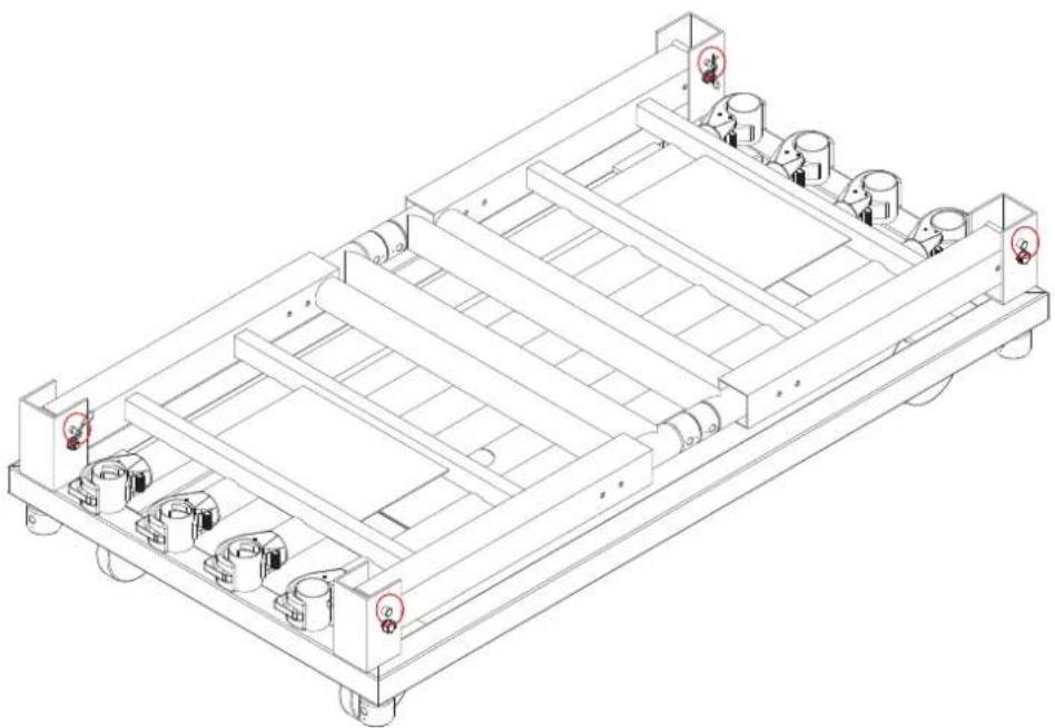
natural_image
Technical line drawing of a mechanical chassis with rollers and wheels (no text or symbols)b. To remove the pin, remove the safety clip first.
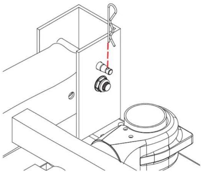
natural_image
Technical line drawing of a mechanical assembly with no visible text or symbolsC.

natural_image
Technical line drawing of a mechanical assembly with a cylindrical component and a red laser beam (no text or symbols)d.
natural_image
Diagram of two large mechanical tractors with red arrows indicating clockwise motion (no text or symbols)e.
natural_image
Technical line drawing of two large industrial carts with wheels and railings (no text or symbols)
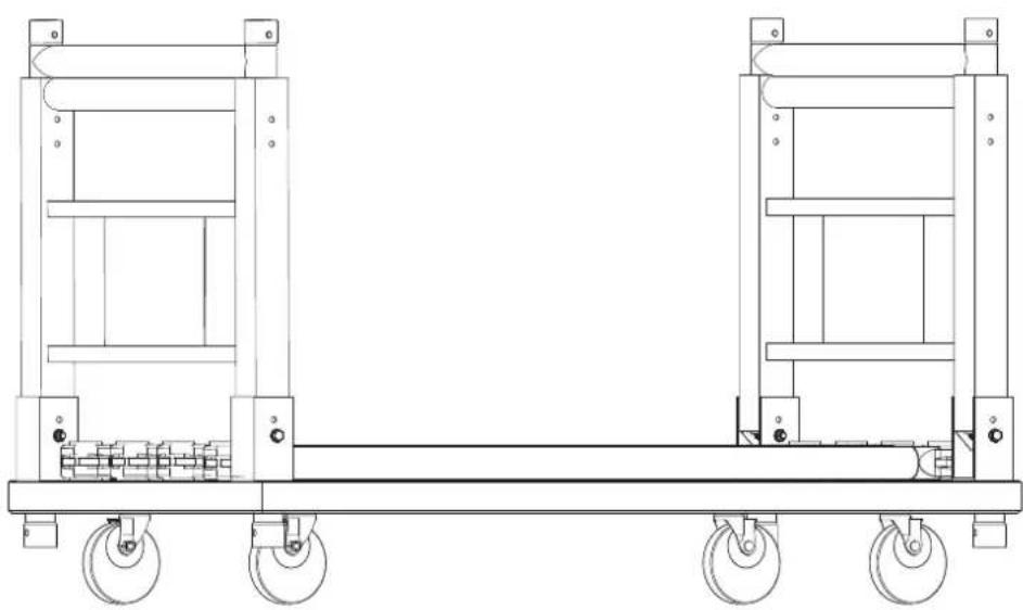
It is possible to remove both of the H frames from the CP Rack. The H frames may then be hung from a truss.
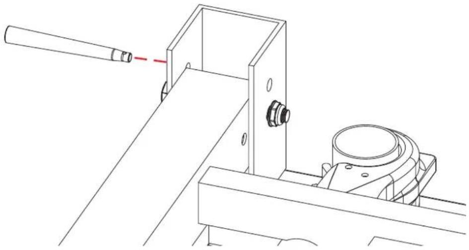
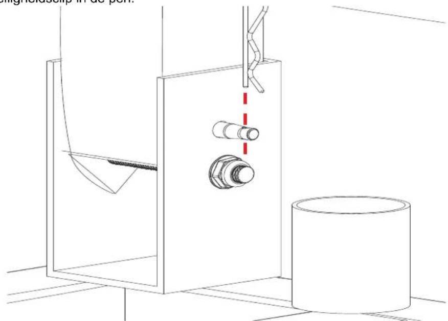
f. Insert the pin to lock the side rail into upright position.
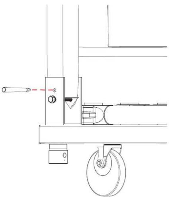
natural_image
Technical line drawing of a mechanical device with wheels and adjustment knobs (no text or symbols)g. Insert the safety clip into the pin.
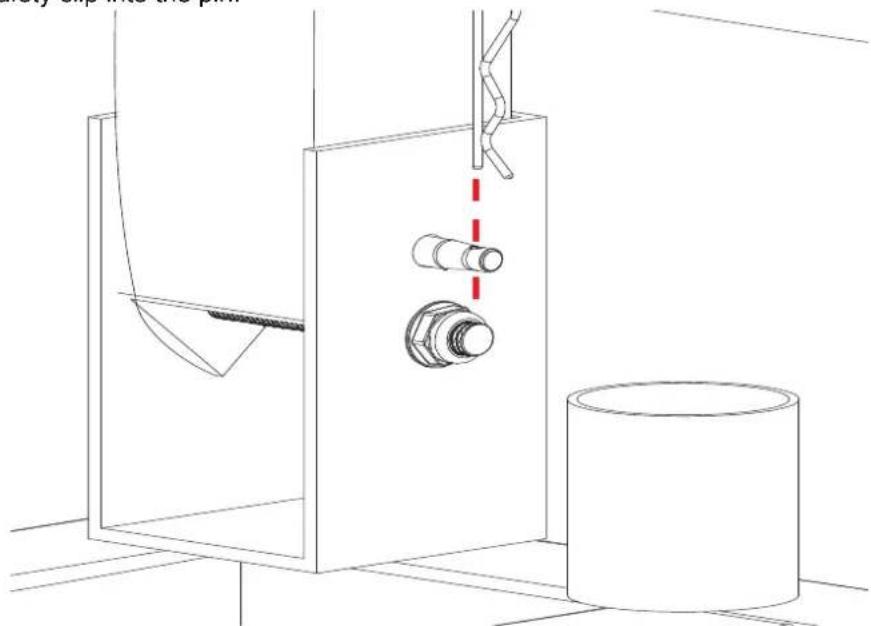
natural_image
Technical line drawing of a mechanical assembly with a cylinder, pipe fittings, and a container (no text or symbols)h. Repeat steps 1-f and 1-g with all bases to lock the side rails.
natural_image
Technical line drawing of a mechanical chassis with mounting feet and railings (no text or symbols)
Warning! Ensure that all attachment points are fully tightened. Failure to do so may cause safety hazards!
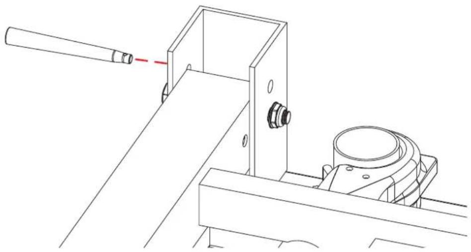
- To detach the tubes from bases:
a. Release the clamp by depressing the switch.
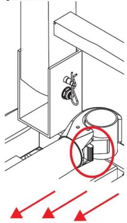
natural_image
Technical diagram of a mechanical assembly with a highlighted component and red arrows indicating direction (no text or symbols)b. Remove the tube.
natural_image
Technical line drawing of a mechanical assembly with red arrows indicating direction (no text or symbols present)c. Repeat the process with the other clamp to release the tube completely.
natural_image
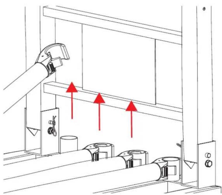
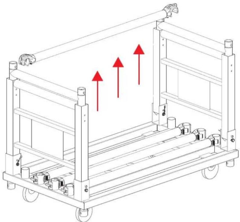
Technical line drawing of a wheeled cart with three red upward arrows indicating motion or force directions (no text or symbols present)- To connect the tube(s) to the H frames:
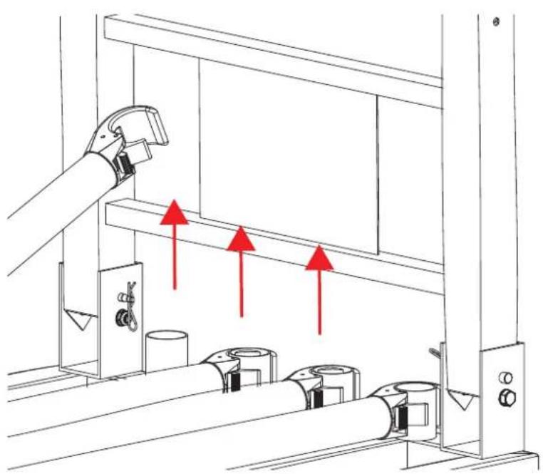
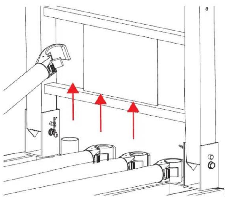
a. Ensure that the clamp is facing down and press the clamp onto the horizontal bar of the H frame.
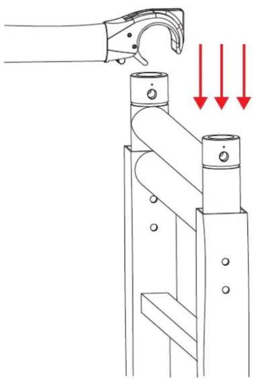
natural_image
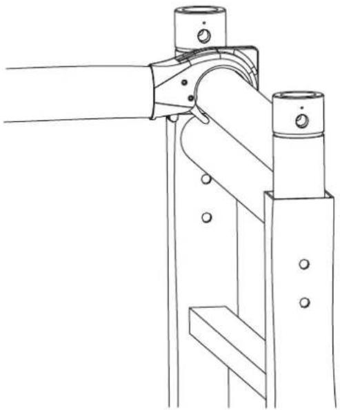
Technical line drawing of a mechanical lever mechanism with red arrows indicating downward motion (no text or symbols)b. Ensure that the clamp is firmly attached to the H frame.
natural_image
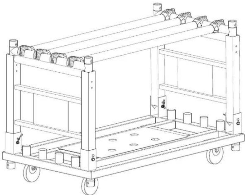
Technical line drawing of a mechanical clamp or bracket assembly (no text or symbols)c. Repeat the previous steps with any other desired tubes:
natural_image
Technical line drawing of a multi-level industrial cart with wheels and structural supports (no text or symbols)
The maximum load capacity for this product is 1,000 lbs. Do not exceed this weight, as failure to do so may cause safety hazards.
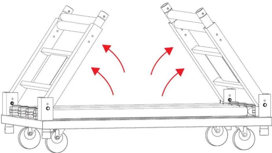
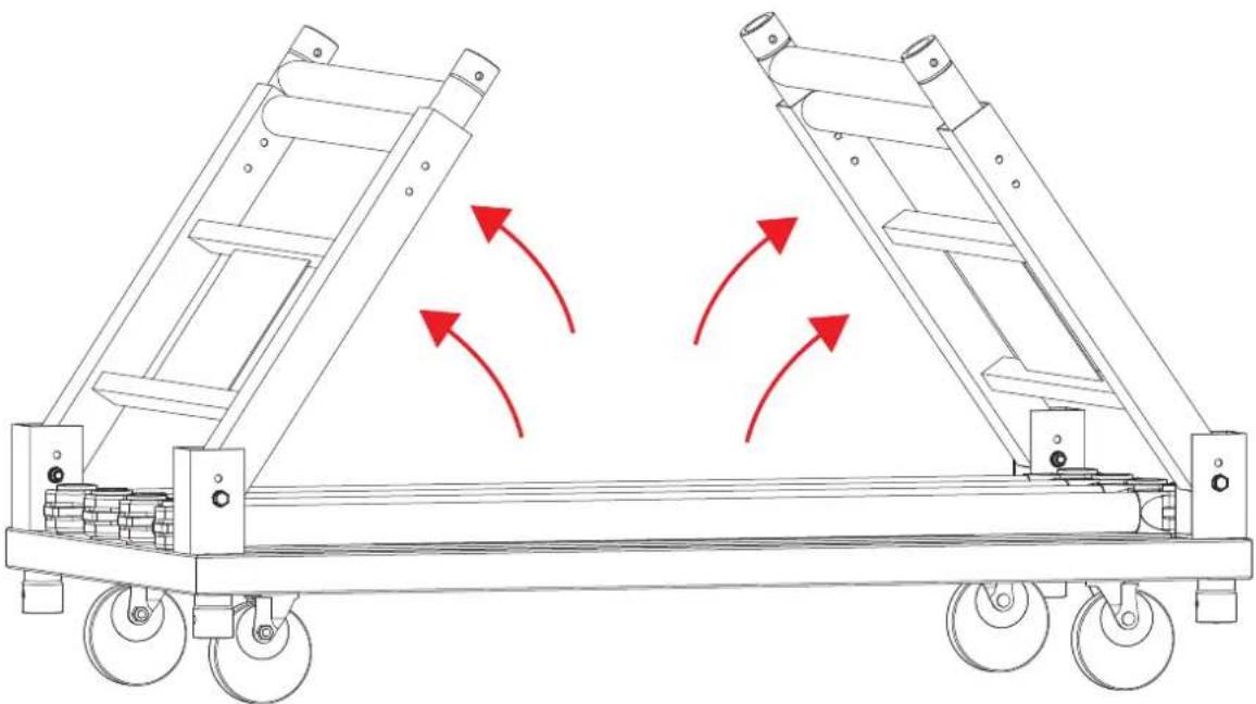
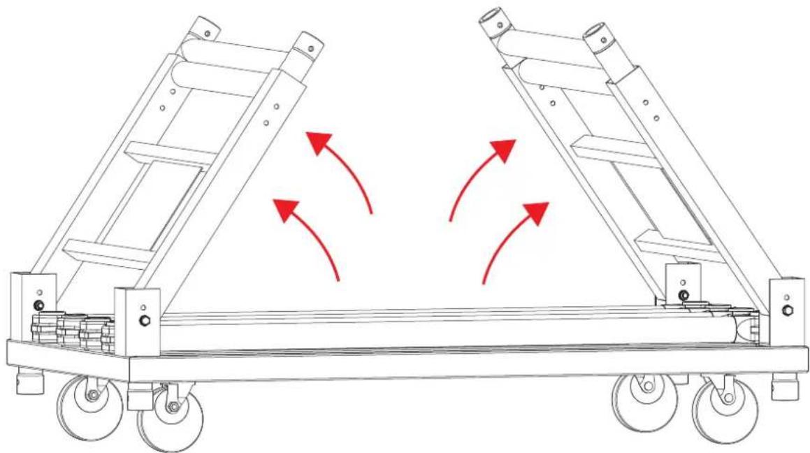
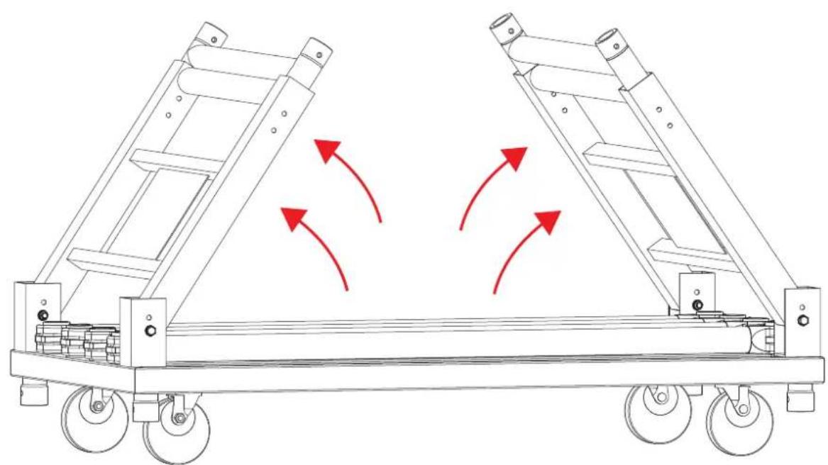
- It is possible to extend the H frames to double the height of the CP Rack. To extend the H frames:
a. Remove safety clips locking H frame in place.
b. Extend or lower the pin to the desired height.
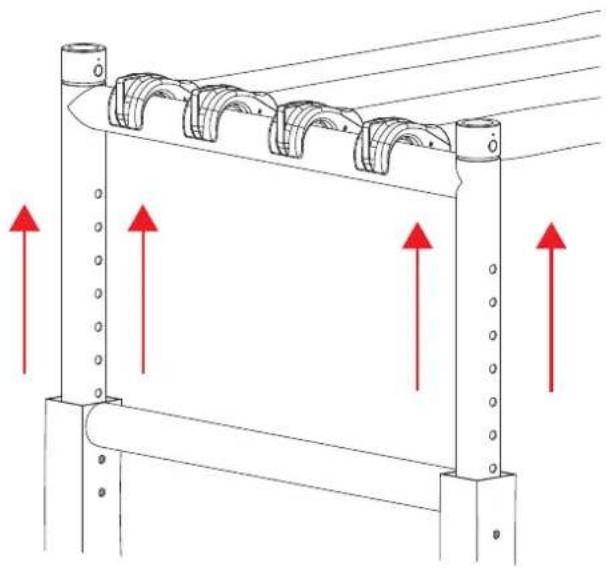
natural_image
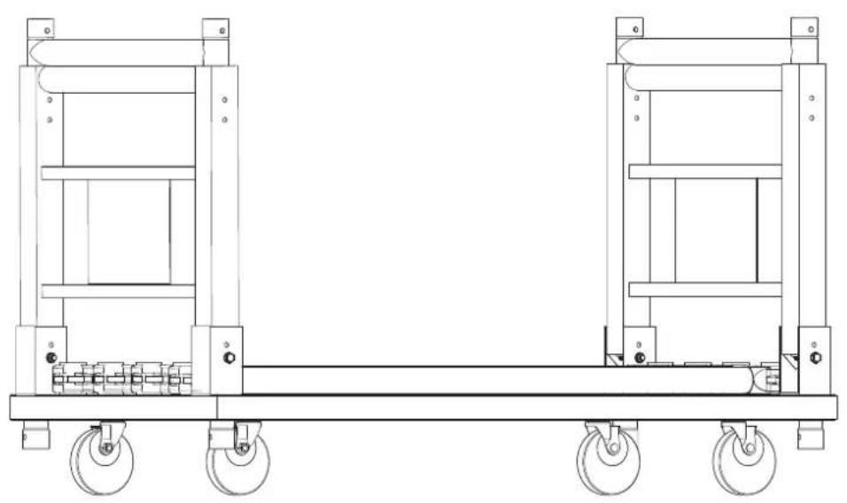
Technical diagram of a mechanical assembly with multiple curved components and red directional arrows indicating motion or force (no text or symbols present)c. Re-insert the safety clips and pins to stabilize the H frames at the desired height.
natural_image
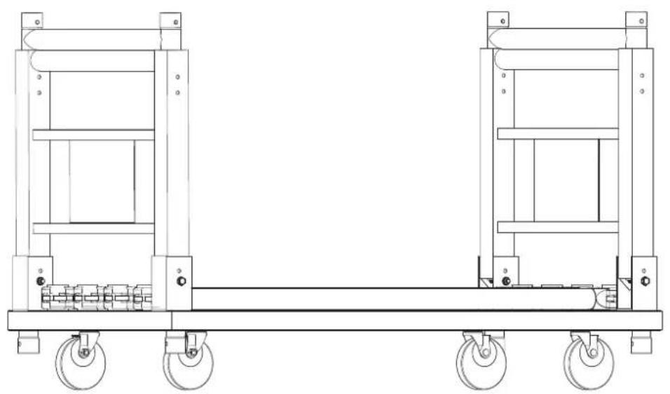
Technical line drawing of a multi-level industrial cart with railings and mounting holes (no text or symbols)
It is possible to stack another CP Rack on top of this product. Maximum stacking is 2 products high.
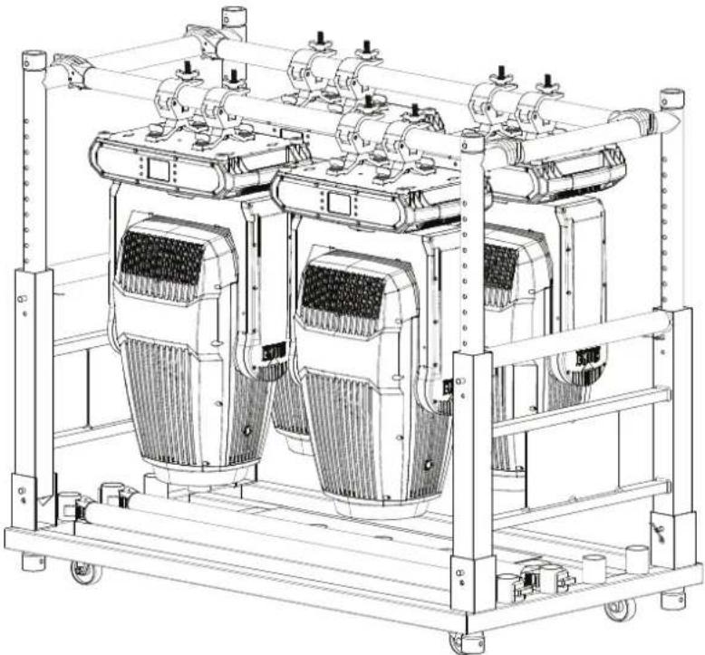
Transporting on Truss or Racks
natural_image
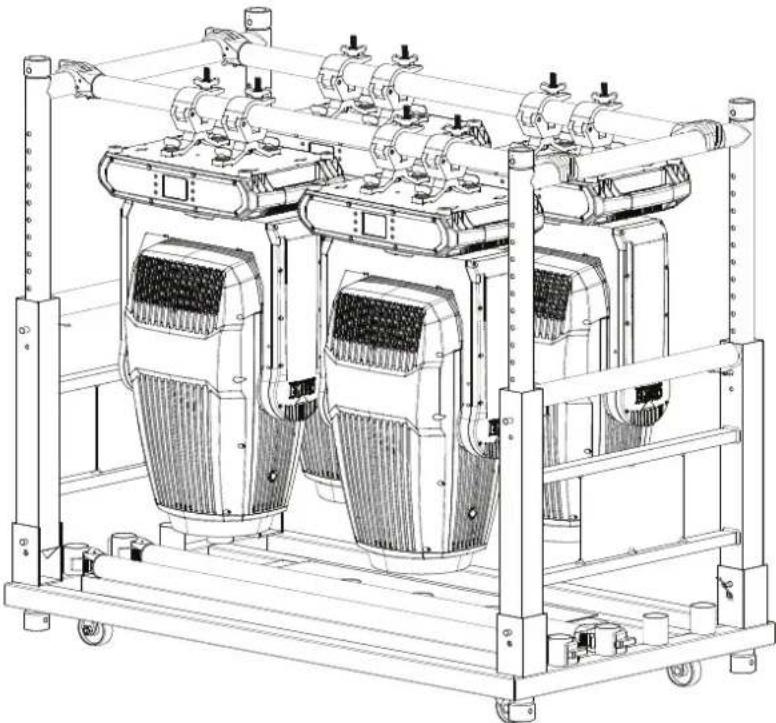
Technical line drawing of a multi-chamber industrial machine with cooling fans and heat exchangers (no text or symbols)
When transporting fixtures in pre-rigged truss and transportation racks, mount fixtures in the vertical position with the lenses facing down and the pan and tilt locks engaged. This is to prevent undue stress on the tilt locks and limit the amount of off-axis bounce on internal components.
natural_image
Technical line drawing of a mechanical chassis with rollers and frame structure (no text or symbols)natural_image
Technical line drawing of a mechanical assembly with no visible text or symbolsC.
natural_image
Technical line drawing of a mechanical assembly with a cylindrical component and a red laser beam (no text or symbols)d.

natural_image
Diagram of two large mechanical tractors with red directional arrows indicating motion or movement (no text or symbols present)e.
natural_image
Technical line drawing of two large industrial carts with wheels and railings (no text or symbols)
natural_image
Technical line drawing of a mechanical cart with wheels and adjustment knobs (no text or symbols)natural_image
Technical line drawing of a mechanical assembly with a cylindrical component and a housing (no text or symbols)natural_image
Technical line drawing of a mechanical frame assembly with mounting feet and internal components (no text or symbols)
natural_image
Technical diagram of a mechanical device with a gear and component, showing red arrows indicating direction (no text or symbols present)b. Retire el tubo.
natural_image
Technical line drawing of a mechanical assembly with red arrows indicating direction (no text or symbols present)natural_image
Technical line drawing of a mechanical cart with three red upward arrows indicating motion or force directions (no text or symbols present)natural_image
Technical line drawing of a mechanical lever mechanism with red arrows indicating downward motion (no text or symbols)natural_image
Technical line drawing of a mechanical assembly with two vertical supports and mounting holes (no text or symbols)natural_image
Technical line drawing of a multi-level industrial cart with wheels and structural supports (no text or symbols)
natural_image
Technical diagram of a mechanical assembly with red arrows indicating upward motion (no text or symbols)natural_image
Technical line drawing of a multi-level mechanical chassis with railings and mounting feet (no text or symbols)
natural_image
Technical line drawing of a multi-chamber industrial machine with cooling fans and heat exchangers (no text or symbols)
natural_image
Technical line drawing of a mechanical chassis with rollers and frame structure (no text or symbols)natural_image
Technical line drawing of a mechanical device with no visible text or symbolsC.
natural_image
Technical line drawing of a mechanical assembly with a cylindrical component and a shaft (no text or symbols)d.
natural_image
Diagram of two large mechanical tractors with red directional arrows indicating motion or movement (no text or symbols present)e.
natural_image
Technical line drawing of two large industrial carts with wheels and railings (no text or symbols)
natural_image
Technical line drawing of a mechanical cart with pulley and handle (no text or symbols)natural_image
Technical line drawing of a mechanical assembly with a cylindrical component and a wall-mounted pipe fitting (no text or symbols)natural_image
Technical line drawing of a mechanical chassis with mounting brackets and support columns (no text or symbols)
natural_image
Technical diagram of a mechanical device with a highlighted component and red arrows indicating direction (no text or symbols)b. Retirez le tube.
natural_image
Technical line drawing of a mechanical assembly with red arrows indicating direction (no text or symbols present)natural_image
Technical line drawing of a wheeled cart with three red upward arrows indicating motion or force directions (no text or symbols present)natural_image
Technical line drawing of a mechanical lever mechanism with red arrows indicating downward motion (no text or symbols)natural_image
Technical line drawing of a mechanical clamp or bracket assembly (no text or symbols)natural_image
Technical line drawing of a multi-level industrial cart with wheels and structural supports (no text or symbols)
natural_image
Technical diagram of a mechanical assembly with multiple curved components and red directional arrows indicating motion or force (no text or symbols present)natural_image
Technical line drawing of a multi-level industrial cart with mounting feet and structural supports (no text or symbols)
natural_image
Technical line drawing of a multi-chamber industrial machine with cooling fans and heat exchangers (no text or symbols)
natural_image
Technical line drawing of a mechanical chassis with rollers and mounting brackets (no text or symbols)natural_image
Technical line drawing of a mechanical device with no visible text or symbolsC.

natural_image
Technical line drawing of a mechanical assembly with a cylindrical component and a red laser beam (no text or symbols)d.
natural_image
Diagram of two large mechanical tractors with red directional arrows indicating motion or movement (no text or symbols present)e.

natural_image
Technical line drawing of two large industrial carts with wheels and railings (no text or symbols)
natural_image
Technical line drawing of a mechanical cart with pulley and handle (no text or symbols)natural_image
Technical line drawing of a mechanical assembly with a cylindrical component and a container, no text or symbols present.natural_image
Technical line drawing of a mechanical chassis with mounting feet and railings (no text or symbols)
natural_image
Technical diagram of a mechanical device with a gear and component, showing red arrows indicating direction (no text or symbols present)natural_image
Technical line drawing of a mechanical assembly with red arrows indicating direction (no text or symbols present)natural_image
Technical line drawing of a mechanical cart with three red upward arrows indicating motion or force directions (no text or symbols present)natural_image
Technical line drawing of a mechanical lever mechanism with red arrows indicating downward motion (no text or symbols)natural_image
Technical line drawing of a mechanical assembly with two vertical supports and mounting holes (no text or symbols)natural_image
Technical line drawing of a multi-level industrial cart with wheels and cylindrical components (no text or symbols)
natural_image
Technical diagram of a mechanical assembly with red arrows indicating upward motion (no text or symbols)natural_image
Technical line drawing of a multi-level mechanical chassis with railings and mounting feet (no text or symbols)
natural_image
Technical line drawing of a multi-chamber industrial machine with cooling fans and heat exchangers (no text or symbols)
Intentionally Left Blank Page
BEKNOPTE HANDLEIDING
NL
Opzetten
natural_image
Technical line drawing of a mechanical assembly with a tool and component (no text or symbols)d.
natural_image
Diagram of two large mechanical tractors with red arrows indicating motion or movement, no text or symbols presente.

natural_image
Technical line drawing of two large industrial carts with wheels and railings (no text or symbols)
natural_image
Technical line drawing of a mechanical cart with pulley and handle (no text or symbols)g. Steek de veiligheidsclip in de pen.
natural_image
Technical line drawing of a mechanical assembly with a cylindrical component and a container, no text or symbols present.natural_image
Technical line drawing of a mechanical chassis with mounting feet and railings (no text or symbols)
natural_image
Diagram of a kitchen appliance with a bag, drawer, and fan, showing red arrows indicating direction (no text or symbols)natural_image
Technical line drawing of a mechanical assembly with red arrows indicating direction (no text or symbols present)natural_image
Technical line drawing of a mechanical cart with three red upward arrows indicating motion or force directions (no text or symbols present)natural_image
Technical line drawing of a mechanical lever mechanism with red arrows indicating downward motion (no text or symbols)natural_image
Technical line drawing of a mechanical assembly with two vertical supports and mounting holes (no text or symbols)natural_image
Technical line drawing of a multi-level industrial cart with wheels and cylindrical components (no text or symbols)
BEKNOPTE HANDLEIDING
NL
Transport op truss of racks
natural_image
Technical line drawing of a multi-chamber industrial machine with cooling fans and heat exchangers (no text or symbols)
Intentionally Left Blank Page
Contact Us
General Information Technical Support
Chauvet World Headquarters
Address: 3360 Davie Rd., Suite 509 Voice: (844) 393-7575
Davie, FL 33314 Fax: (954) 756-8015
Voice: (954) 577-4455 Email: chauvetcs@chauvetlighting.com
Fax: (954) 929-5560
Toll Free: (800) 762-1084 Website: www.chauvetdj.com
Chauvet U.K.
Address: Pod 1 EVO Park Email: UKtech@chauvetlighting.eu
Little Oak Drive, Sherwood Park
Nottinghamshire, NG15 0EB Website: www.chauvetdj.eu
UK
Voice: +44 (0) 1773 511115
Fax: +44 (0) 1773 511110
Chauvet Benelux
Address: Stokstraat 18 Email: BNLtech@chauvetlighting.eu
9770 Kruishoutem
Belgium Website: www.chauvetdj.eu
Voice: +32 9 388 93 97
Chauvet France
Address: 3, Rue Ampère Email: FRtech@chauvetlighting.fr
91380 Chilly-Mazarin
France Website: www.chauvetdj.eu
Voice: +33 1 78 85 33 59
Chauvet Germany
Address: Bruno-Bürgel-Str. 11 Email: DEtech@chauvetlighting.de
28759 Bremen
Germany Website: www.chauvetdj.eu
Voice: +49 421 62 60 20
Chauvet Mexico
(Entrance by Calle 2)
Zona Industrial Lerma
Website: www.chauvetdj.mx
Visit the applicable website above to verify our contact information and instructions to request support. Outside the U.S., U.K., Ireland, Mexico, France, Germany, or Benelux, contact the dealer of record.
UK CA
CE
RoHS

- CP RACK
- Quick Reference Guide
- Intentionally Left Blank Page
- Safety Notes
- What is Included
- Symbols
- Product Overview
- Setup
- To begin setup:
- Transporting on Truss or Racks
- BEKNOPTE HANDLEIDING
- NL
- Opzetten
- Transport op truss of racks
- Contact Us
- General Information Technical Support
- Chauvet World Headquarters
- Chauvet U.K.
- Chauvet Benelux
- Chauvet France
- Chauvet Germany
- Chauvet Mexico
Brand : Chauvet
Model : CP Rack
Category : Lighting