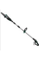
GATS-E 20 Li - Saw Gardol - Free user manual and instructions
Find the device manual for free GATS-E 20 Li Gardol in PDF.


| Product type | Cordless pole pruner (telescopic chainsaw) |
| Brand | Gardol |
| Model | GATS-E 20 Li |
| Power supply | Lithium-ion battery (Power-X-Change) 20 V |
| Compatible battery capacities | 1.5 Ah, 3.0 Ah, 4.0 Ah (Li-Ion) |
| Charger | Mains voltage 200-250 V ~ 50-60 Hz, output 21 V DC, 3000 mA |
| Blade length | 200 mm |
| Maximum cutting length | 170 mm |
| Chain pitch | 3/8", 33 teeth |
| Chain gauge | 1.3 mm (0.050") |
| Cutting speed (at nominal speed) | 3.76 m/s |
| Oil tank capacity | 125 cm³ |
| Net weight (without accessories) | 3.4 kg |
| Sound pressure level L_pA | 81.05 dB(A) (uncertainty K=3 dB) |
| Guaranteed sound power level L_WA | 102 dB(A) |
| Vibration emission value (handle) | 0.947 m/s² (uncertainty K=1.5 m/s²) |
| Recommended working angle | Max. 60° from horizontal |
| Safety distance from power lines | Minimum 10 m |
| Chain and guide bar materials | Oregon 91P033X or Kangxin 3/8 8050X33DL chain; Oregon 080NDEA041 or Kangxin AP08-33-507P bar |
| Safety devices | Start lock, carrying belt with safety release, blade guard |
| Wear parts | Bar, battery, saw chain |
| Maintenance and cleaning | Regular cleaning with a damp cloth, automatic chain lubrication, check chain tension every 10 minutes |
| Warranty period | 84 months (7 years) |
| Storage temperature | 5 °C to 30 °C, dry and frost-free place |
Frequently Asked Questions - GATS-E 20 Li Gardol
User questions about GATS-E 20 Li Gardol
0 question about this device. Answer the ones you know or ask your own.
Ask a new question about this device
Download the instructions for your Saw in PDF format for free! Find your manual GATS-E 20 Li - Gardol and take your electronic device back in hand. On this page are published all the documents necessary for the use of your device. GATS-E 20 Li by Gardol.
USER MANUAL GATS-E 20 Li Gardol
GB Original operating instructions Pole-mounted cordless pruner
natural_image
Close-up of a hand holding a mechanical component with a labeled part 'C' (no text or symbols on the object itself)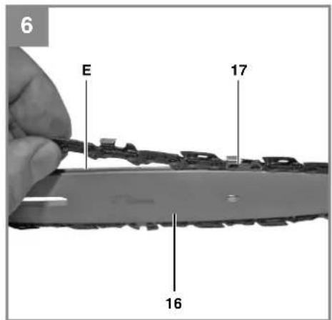
natural_image
Close-up of a hand adjusting a camera lens component with an arrow indicating rotation (no text or symbols visible)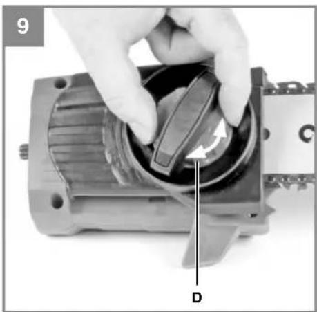
natural_image
Close-up of a hand holding a mechanical component with a labeled arrow and letter D, no readable text or symbols present.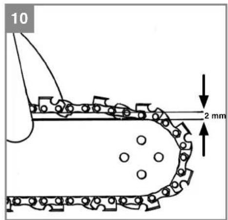

natural_image
Close-up of a hand adjusting a black belt buckle, with two arrows pointing to the buckle (no text or symbols visible)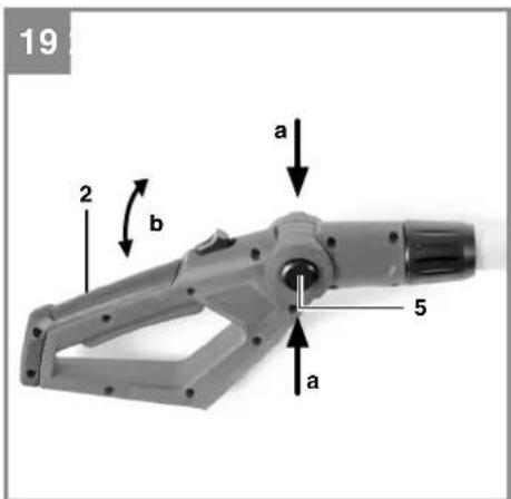
natural_image
Close-up of a hand inserting a device into a device with a labeled component (no visible text or symbols)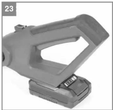
natural_image
Exterior view of a gray handheld device with a black handle and base (no visible text or symbols)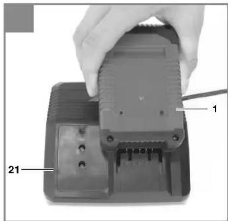
-7-
DE
Gefahr!
When using the equipment, a few safety precautions must be observed to avoid injuries and damage. Please read the complete operating instructions and safety regulations with due care. Keep this manual in a safe place, so that the information is available at all times. If you give the equipment to any other person, hand over these operating instructions and safety regulations as well. We cannot accept any liability for damage or accidents which arise due to a failure to follow these instructions and the safety instructions.
1. Safety regulations
The corresponding safety information can be found in the enclosed booklet.
Danger!
Read all safety regulations and instructions. Any errors made in following the safety regulations and instructions may result in an electric shock, fire and/or serious injury.
Keep all safety regulations and instructions in a safe place for future use.
This appliance is not intended for use by persons (including children) with reduced physical, sensory or mental capabilities, or lack of experience and knowledge, unless they have been given supervision or instruction concerning use of the appliance by a person responsible for their safety. Children should be supervised to ensure that they do not play with the appliance.
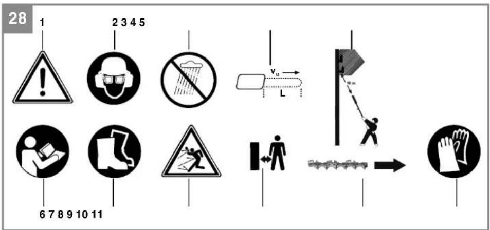
Explanation of the symbols on the equipment (Fig. 28):
- Warning!
- Wear safety goggles, a face guard and ear protection.
- Protect the equipment from rain and damp.
- Maximum cutting length of the pole-mounted pruner.
- Electric shock can cause fatal injury. Keep a distance of at least 10 m from power cables.
- Read the directions for use before operating the equipment.
- Wear sturdy, non-slip footwear.
- Watch out for falling and catapulting parts.
- Keep your distance.
- Direction of the chain movement and teeth of the pole-mounted pruner.
- Wear safety gloves.
2. Layout and items supplied
2.1 Layout (Fig. 1)
- Handle
- On/Off switch
- Safety lock-off
- Safety lock-off for the handle angle adjuster
- Assembly nut
- Tube
- Shoulder strap with safety release
- Additional handle
- Telescopic tube 1 lock nut
- Telescopic tube 1
- Telescopic tube 2 lock nut
- Telescopic tube 2 with motor housing
- Safety lock-off for the motor housing angle adjuster
- Chain saw mounting kit
- Cutter bar
- Saw chain
- Cutter guard
2.2 Items supplied
Please check that the article is complete as specified in the scope of delivery. If parts are missing, please contact our service center or the sales outlet where you made your purchase at the latest within 5 working days after purchasing the product and upon presentation of a valid bill of purchase. Also, refer to the warranty table in the service information at the end of the operating instructions.
- Open the packaging and take out the equipment with care.
- Remove the packaging material and any packaging and/or transportation braces (if available).
- Check to see if all items are supplied.
- Inspect the equipment and accessories for transport damage.
- If possible, please keep the packaging until the end of the guarantee period.
Danger!
The equipment and packaging material are not toys. Do not let children play with plastic bags, foils or small parts. There is a danger of swallowing or suff ocating!
• Complete handle
• Complete tube with motor unit
• Shoulder strap with safety release
• Chain saw mounting kit
- Cutter bar
GB
- Saw chain
- Cutter guard
• Original operating instructions - Safetyinstructions
3. Proper use
Pole-mounted pruner (chainsaw with telescopic handle)
The chain saw mounting kit is allowed to be used only on the supplied motor head.
The chainsaw with telescopic handle is designed for lopping off tree branches. It is not suitable for extensive sawing work, felling trees or sawing any materials other than wood.
The equipment is to be used only for its prescribed purpose. Any other use is deemed to be a case of misuse. The user / operator and not the manufacturer will be liable for any damage or injuries of any kind caused as a result of this.
Please note that our equipment has not been designed for use in commercial, trade or industrial applications. Our warranty will be voided if the machine is used in commercial, trade or industrial businesses or for equivalent purposes.
4. Technical data
Pole-mounted pruner
Cutter bar length: 200 mm
Max. cutting length: 170 mm
Chain pitch: 3/8", 33 teeth
Chain thickness: (0.050") 1.3 mm
Sprocket wheel: 6 teeth, 3/8"
Cutting speed
at rated rpm: 3.76 m/s
Oil tank capacity: 125 cm3
Net weight without accessories: 3.4 kg
Saw chain: .....Oregon 91P033X, ....Kangxin 3/8 8050X33DL
Cutter bar: ..... Oregon 080NDEA041 (520089), ....Kangxin AP08-33-507P
Important!
The equipment is supplied without batteries and without a charger is allowed to be used only with the lithium-ion batteries of the Power-X-Change series!
Power-X-Change
20 V, 1.5 Ah 5 lithium-ion cells
20 V, 3.0 Ah 10 lithium-ion cells
20 V, 4.0 Ah 10 lithium-ion cells
The lithium-ion batteries of the Power-X-Change series are allowed to be charged only with the Power-X charger.
Charging unit
Mains voltage 200-250 V \~ 50-60 Hz
Output
Rated voltage 21 V d. c.
Rated current 3000 mA
Danger!
Sound and vibration
Sound and vibration values were measured in accordance with ISO 22868.
L_pA sound pressure level 81.05 dB(A)
K_nA uncertainty 3 dB
LWA sound power level measured .. 98.23 dB(A)
K_WA uncertainty 3 dB
LWA sound power level guaranteed ... 102 dB(A)
Wear ear-muff s.
The impact of noise can cause damage to hearing.
Total vibration values (vector sum of three directions) determined in accordance with ISO 22867.
Handle under load
Vibration emission value a_n = 0.947m / s^2
K uncertainty = 1.5 m/s²
The specified vibration value was established in accordance with a standardized testing method. It may change according to how the electric equipment is used and may exceed the specified value in exceptional circumstances.
The specified vibration value can be used to compare the equipment with other electric power tools.
The specified vibration value can be used for initial assessment of a harmful effect.
Keep the noise emissions and vibrations to a minimum.
GB
- Only use appliances which are in perfect working order.
• Service and clean the appliance regularly.
• Adapt your working style to suit the appliance.
• Do not overload the appliance. - Have the appliance serviced whenever necessary.
- Switch the appliance off when it is not in use.
• Wear protective gloves.
5. Before starting the equipment
The equipment is supplied without batteries and without a charger.
Caution! Do not fit the battery until the equipment has been fully assembled and all the settings have been actuated. Always wear protective gloves when working on the equipment to protect yourself against injury. Carefully unpack all parts and check that they are complete (Fig. 1).
5.1 General information on assembly
a) Fig. 2-3: Push the tube (7) onto the handle housing (2a) as far as the bead (7a) and screw it tight with the assembly nut (6).
b) Fig. 4: Hook the carabiner (A) of the shoulder strap (8) into the strap attachment (B).
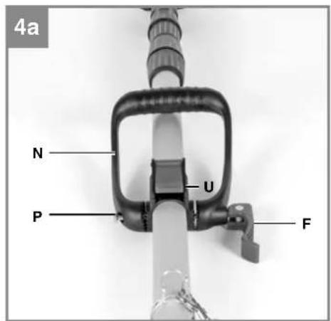
c) Fig. 4a: The additional handle consists of the handle (N), the hexagon screw (P) and the lock (F). It is fitted to the handle attachment (U) as illustrated. Push the hexagon screw (P) into the handle (N) and screw it tight to the lock (F).
5.2 Fitting the chain saw mounting kit (for use as a pole-operated pruner)
5.2.a Assembly of the cutter rail and the saw chain
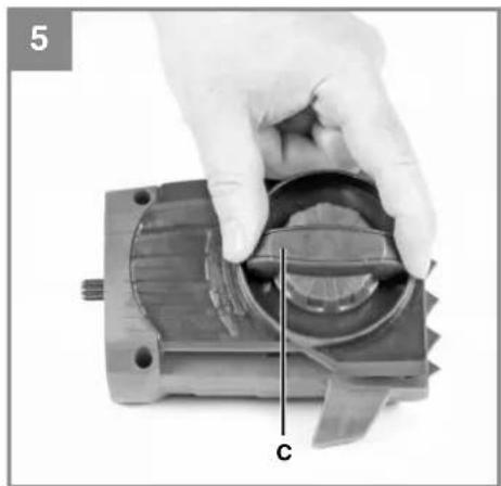
- Undo the fixing screw (C) of the chain wheel cover (Fig. 5).
• Take off the chain wheel cover. - Lay the chain as shown in the groove which runs around the cutter rail (Fig. 6/Item E).
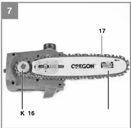
- Insert the cutter rail and chain as shown in the mounting in the chainsaw (Fig. 7). At the same time guide the chain around the chain wheel (Fig. 7/Item K).
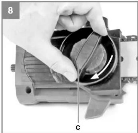
- Attach the chain wheel cover (Fig. 8/Item C) and fasten it hand-tight with the fastening screw.
Important! Do not fully tighten the fastening screw
until after you have adjusted the chain tension (see section 5.2.b).
5.2.b Tensioning the saw chain
Caution! Always remove the battery from the device before inspection and adjustment. Always wear protective gloves when working on the chainsaw to protect yourself against injury.
- Undo the fixing screw (C) of the chain wheel cover a few turns (Fig. 5).
- Adjust the chain tension with the chain tensioning screw (Fig. 9/Item D). Turning the screw clockwise increases the chain tension, turning it counter-clockwise decreases the chain tension. The saw chain is correctly tensioned if it can be lifted approx. 2mm in the middle of the cutter rail (Fig. 10).
- Secure the fixing screw (C) of the chain wheel cover (Fig. 8).
Notice! All the chain links must lie properly in the guide groove of the cutter bar.
Notes on tensioning the chain:
The saw chain must be properly tensioned to ensure safe operation. You can tell that the chain tension is perfect if the saw chain can be lifted by around 2 mm in the middle of the cutter rail. As the saw chain heats up during cutting and thus changes in length, check the chain tension no less than every 10 minutes and adjust it again as required. This applies in particular to new saw chains. When you have fi nished working slacken the chain again, as the chain will shorten when it cools down. This will prevent the chain from being damaged.
5.2.c Saw chain lubrication
Caution! Always remove the battery from the device before inspection and adjustment. Always wear protective gloves when working on the chainsaw to protect yourself against injury.
Important! Never operate the chain if it is not lubricated with saw chain oil. Use of the chainsaw without saw chain oil or if the oil level is below the viewing window will result in damage to the chainsaw!
Important! Be aware of the temperature conditions: different lubricants with completely different viscosities are required at different ambient temperatures. At lower temperatures you will need low viscosity oils in order to achieve a sufficient lubricating film. However, if the same low viscosity oil is used during the summer it will become even
GB
thinner due to the ambient temperatures alone, and as a result the lubricating fi lm could break down, causing the chain to overheat and become damaged. In addition, the chain oil would burn and produce unnecessary pollutants.
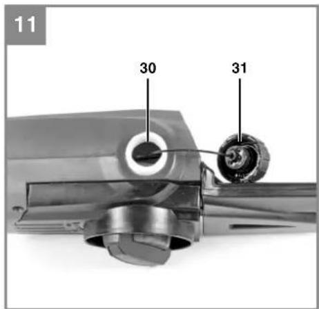
Filling the oil tank (Fig. 11):
- Place the chainsaw on a flat surface.
- Clean the area around the oil tank cover (Item 31) and then clean the oil tank cover.
- Fill the tank (Item 30) with saw chain oil. In the process, make sure that no dirt enters the tank, as this could cause the oil nozzle to become blocked.
- Close the oil tank cover (Item 31).
After the chain saw mounting kit has been fitted and when the equipment is not being used, slip the cutter guard (Fig. 1/Item 18) over the mounted cutter bar with saw chain in order to prevent injuries.
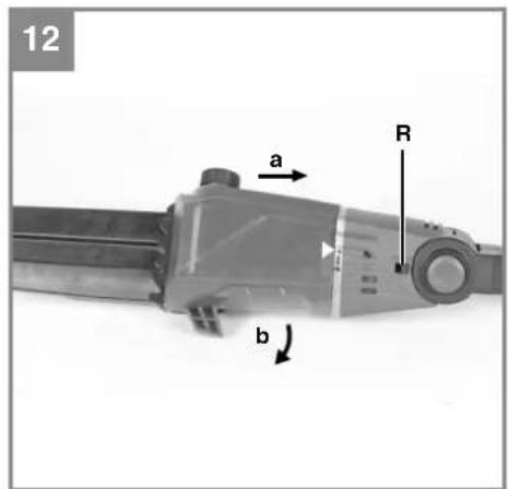
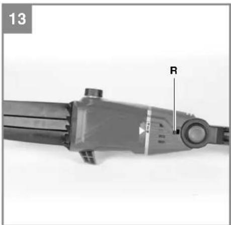
5.3 Fitting the chain saw mounting kit to the motor head (Fig. 12 - 13)
The cutter guard must be slipped over the mounted cutter bar with saw chain in order to prevent injuries.
- Position the chain saw mounting kit and the motor head such that the arrows on both parts coincide.
- Press the chain saw mounting kit against the motor head. This will cause the lock button (R) to be pushed to the right. Turn the chain saw mounting kit clockwise. The chain saw mounting kit will lock onto the motor head and is then secured in place. This will cause the lock button (R) to be pushed to the left.
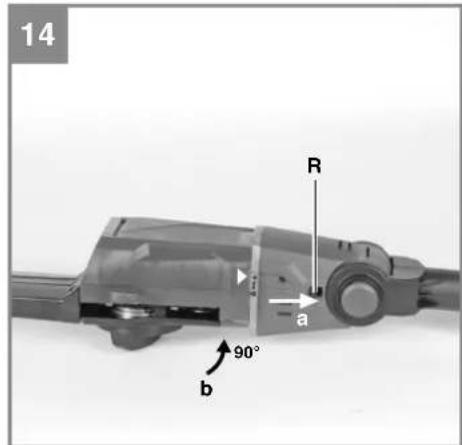
5.4 Turning the chain saw mounting kit through 90° on the motor head (Fig. 14)
The cutter guard must be slipped over the mounted cutter bar with saw chain in order to prevent injuries.
- Pull the lock button (R) to the right.
- Turn the chain saw mounting kit 90° counterclockwise. The chain saw mounting kit will lock onto the motor head and is then secured in place.
5.5 Removing the chain saw mounting kit from the motor head (Fig. 12 - 13)
The cutter guard must be slipped over the mounted cutter bar with saw chain in order to prevent injuries.
-
Pull the lock button (R) to the right.
-
Turn the chain saw mounting kit to the point where the arrows on the motor head and chain saw mounting kit coincide, allowing the mounting kit to be removed.
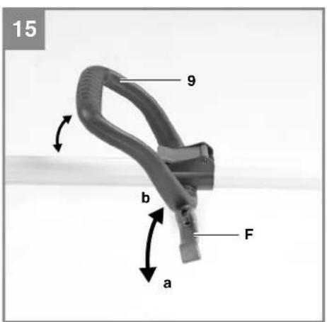
5.6 Adjusting the additional handle (Fig. 15-16)
(a) Setting the tilt of the additional handle Open (a) the lock (F). Set the desired tilt of the additional handle (9). Close (b) the lock (F).
b) Shifting the additional handle
Open (a) the lock (H) and slide the additional handle (9) into the required position. Close (b) the lock (H).
5.7 Using the shoulder strap
Warning! Always use the shoulder strap when working with the equipment. Switch off the equipment before you take off the shoulder strap (risk of injury).
- Hook the carabiner (Fig. 4/Item A) into the strap holder.
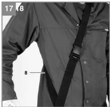
- Slip the shoulder strap (Fig. 17/Item 8) over your shoulder.
- Adjust the length of the shoulder strap so that the strap attachment is at waist level (Fig. 17).
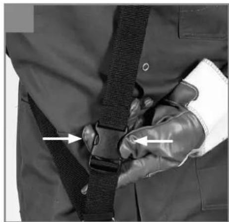
- The shoulder strap is equipped with a buckle. Press the hooks together (Fig. 18) if you need to put down the equipment quickly.
- To change the strap position on the equipment, press together the two metal loops (Fig. 4/Item L / M) and adjust the strap attachment on the tube.
5.8. Adjusting the angle of the handle (Fig. 19)
Press the two safety lock-off s (5) and adjust the angle of the handle (2) to any of 4 latching positions.
5.9. Adjusting the angle of the motor housing (Fig. 20)
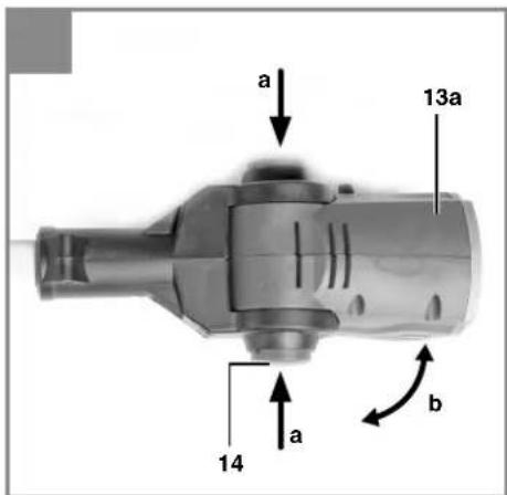
Press the two safety lock-off s (14) and adjust the angle of the motor housing (13a) to any of 7 lat-ching positions.
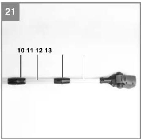
5.10 Adjusting the telescopic tube (Fig. 21)
- Undo the telescopic tube lock nuts (10 + 12) by turning them counter-clockwise.
- Pull out the telescopic tubes (11 + 13) to suit the required working height.
- Secure the telescopic tube lock nuts (10 + 12) by them turning clockwise.
GB
5.11 Fitting the battery (Fig. 22 - 23)
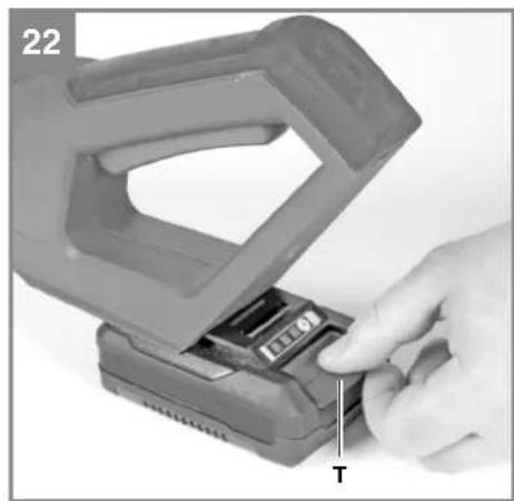
Press the side pushlock button (T) of the battery pack as shown in Fig. 22 and push the battery pack into the mount provided. When the battery pack is positioned as in Fig. 23, make sure that the pushlock button latches in place! To remove the battery pack, proceed in reverse order.
5.12 Charging the battery (Fig. 24)
- Take the battery pack out of the equipment. Do this by pressing the pushlock button (T).
- Check that your mains voltage is the same as that marked on the rating plate of the battery charger. Insert the power plug of the charger (21) into the mains socket outlet. The green LED will then begin to flash.
- Insert the battery pack (1) into the battery charger (21).
- In the section entitled „Charger indicator“ you will find a table with an explanation of the LED indicator on the charger.
The battery pack can become a little warm during the charging. This is normal.
If the battery pack fails to charge, check:
• whether there is voltage at the socket outlet
- whether there is good contact at the charging contacts.
If the battery pack still fails to charge, send
• the charging unit
• and the battery pack
to our customer service center.
To ensure that the battery pack provides long service, you should take care to recharge it promptly. You must recharge the battery pack when you notice that the power of the cordless equipment drops. Never fully discharge the battery pack. This will cause it to develop a defect.
6. Operation
Please note that the statutory regulations governing noise abatement may differ from one location to another.
Caution! Always use the shoulder strap when working with the equipment. Always switch off the equipment before you take off the shoulder strap. Otherwise there is a risk of injury.
Put on the shoulder strap as described above, fi t the required mounting kit and adjust the equipment to suit your needs.
Switching on/off
Switching on
- Hold the equipment by the handles with both hands (thumbs under the additional handle).
- Slide the safety lock-off (Fig. 3/Item 4) to the front and hold.
- Switch on the equipment with the On/Off switch (Fig. 3/Item 3). You can then release the safety lock-off.
Switching off
Release the On/Off switch (Fig. 3/Item 3).
7. Working with the chainsaw mounting kit
Preparations
To ensure that you can work safely, check the following points before every use:
Condition of the chainsaw
Inspect the chainsaw before the start of work for damage to the housing, the power cable, the saw chain and the cutter rail. Never use a chainsaw which is obviously damaged.
Oil container
Fill level of the oil container. Even while working, keep checking that sufficient oil is in the system. To avoid damaging the chainsaw, never run the saw if there is no oil in the system or if the oil drops below the "min" mark. On average, a single fi lling will last around 20 minutes depending on the number of pauses in cutting and the loads involved.
Saw chain
Tension of the saw chain, condition of the cutting elements. The sharper the chainsaw, the easier and more controllable it is to operate the chainsaw. The same also applies to the chain tension. Also while working you should check the chain tension no less than every 10 minutes in order to increase your safety. New saw chains in particular often tend to expand more.
GB
Safety clothing
Always wear appropriate tight-fi tting safety clothing like special trousers which protect against cuts, protective gloves and safety shoes.
Hearing protection and protective goggles.
Wear a protective helmet with integral face and hearing protection. This will offer protection against falling branches and any branches if they spring back.
Safe working
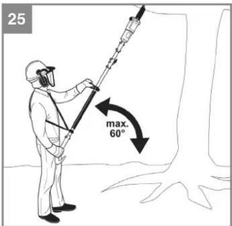
- To ensure that you can work in safety you must use the equipment at a working angle of max. 60°.
- Never stand under the branch you want to saw.
• Use special caution when working with branches under tension and splintered wood. - Possible risk of injury caused by falling branches and catapulting pieces of wood.
- When the equipment is in operation keep other persons and animals away from the danger zone.
- The equipment is not protected from electric shock through contact with high-voltage cables. Keep a minimum distance of 10 m from live cables. Electric shock can cause fatal injury.
- When working on slopes always stand to the upper or left or right side of the branch you wish to cut.
- Hold the equipment as close as possible to your body. This will help you to keep your balance.
Cutting techniques
- When removing branches, hold the equipment at an angle of max. 60° to the horizontal to avoid being hit by a falling branch (Fig. 25).
- Start with the bottom branches on the tree. This will make it easier for the cut branches to drop.
- After completing a cut, the weight of the saw will abruptly increase for the operator as the saw is no longer supported by the branch. This can result in you losing control over the saw.
- Remove the saw from the cut only with the saw chain still running. This will prevent the saw from getting jammed.
• Never cut with the tip of the saw. - Never cut into the bulging branch collar. This will prevent the tree from healing.
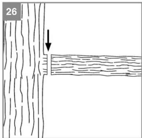
Sawing off smaller branches (Fig. 26):
Place the contact surface of the saw onto the branch. This will prevent the saw from making jerky movements when you begin a cut. Exerting slight pressure, guide the saw from the top to the bottom through the branch.
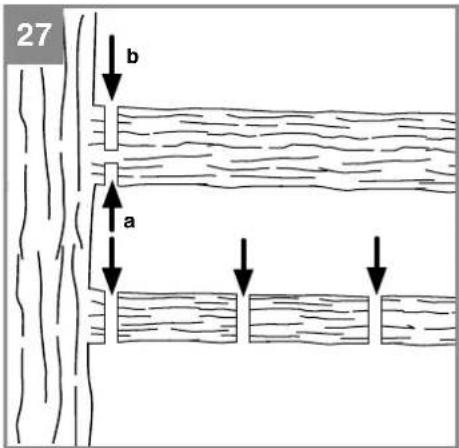
Sawing off larger and longer branches (Fig. 27):
Carry out a relief cut when working on larger branches.
Start by sawing through 1/3 of the branch diameter (a) from the bottom to the top with the top side of the cutter rail. Then saw towards the first cut (b) from the top to the bottom with the bottom side of the cutter rail.
Saw off longer branches in several steps to keep control over the impact location.
Kick-back!
The term “kickback” describes what happens when the running chainsaw suddenly kicks upward and backward. Usually, this is caused by contact between the tip of the cutter rail and the workpiece or the saw chain becoming trapped. In the event of kickback, large forces occur suddenly and violently. As a result, the chainsaw usually reacts uncontrollably. This can often result in very serious injuries to the worker or persons in the vicinity. The risk of kickback is at its greatest when the saw is positioned for a cut in the region of the tip of the cutter rail, as the leverage effect is greatest there. It is therefore safest to position the saw as flat as possible.
Important!
• Make sure that the chain tension is always correctly adjusted.
- Only use a chainsaw if it is in perfect working order.
- Only work with a saw chain that has been properly sharpened in accordance with the instructions.
- Never cut with the upper edge or the tip of the cutter rail.
• Always hold the chainsaw firmly with both hands.
Cutting wood which is under tension
Special care is required when cutting wood which is under tension. Wood which is under tension from which it is released by cutting may in some cases react completely unpredictably and uncontrollably. In the worst case this could result in extremely severe or even fatal injuries. This type
GB
of work must only be performed by persons who have been specially trained.
8. Cleaning, maintenance and ordering of spare parts
Danger!
Remove the battery pack before doing any cleaning and maintenance work.
8.1 Cleaning
- Regularly clean the clamping mechanism by blowing it out with compressed air or cleaning it with a brush. Do not use tools for cleaning.
- Keep the handles free of grease so that you can maintain a firm grip.
- Clean the equipment as required with a damp cloth and, if necessary, mild washing up liquid.
- If the chainsaw is not to be used for an extended period of time then you should remove the chain oil from the tank. Briefly immerse the saw chain and the cutter rail in an oil bath and then wrap them in oil paper.
- Never immerse the equipment in water or other liquids in order to clean it.
- Use a brush to remove deposits from the safety guards.
- Keep all safety devices, air vents and the motor housing free of dirt and dust as far as possible. Wipe the equipment with a clean cloth or blow it with compressed air at low pressure.
• We recommend that you clean the device immediately each time you have finished using it. - Clean the equipment regularly with a moist cloth and some soft soap. Do not use cleaning agents or solvents; these could attack the plastic parts of the equipment. Ensure that no water can seep into the device. The ingress of water into an electric tool increases the risk of an electric shock.
8.2 Maintenance
Replacing the saw chain and cutter rail
The cutter rail needs to be replaced if the guide groove of the cutter rail is worn; Proceed as described in the section "Assembly of the cutter rail and the saw chain".
Checking the automatic chain lubrication
You should check the operation of the automatic chain lubrication system on a regular basis in order to guard against overheating and the associated damage to the cutter rail and the saw chain. To do this, point the tip of the cutter rail towards a smooth surface (board, section of a cut tree) and allow the chainsaw to run. If an increasing oil trace becomes evident during this process then the automatic chain lubrication system is working properly. If no clear oil trace is evident then please refer to the corresponding instructions in "Troubleshooting". If the information contained there still fails to remedy the situation then please contact our service department or another similarly qualified workshop.
Important! Do not actually touch the surface with the tip of the cutter rail when performing this test. Keep a safe distance (approx. 20 cm).
Sharpening the saw chain
Eff ective working with the chainsaw is only possible if the saw chain is in good condition and sharp. This also reduces the risk of kickback. The saw chain can be re-sharpened by any dealer. Do not attempt to sharpen the saw chain yourself unless you have the necessary special tools and experience.
8.3 Ordering replacement parts:
Please quote the following data when ordering replacement parts:
• Type of machine
• Article number of the machine
• Identification number of the machine
- Replacement part number of the part required For our latest prices and information please go to www.isc-gmbh.info
GB
9. Disposal and recycling
The equipment is supplied in packaging to prevent it from being damaged in transit. The raw materials in this packaging can be reused or recycled. The equipment and its accessories are made of various types of material, such as metal and plastic. Never place defective equipment in your household refuse. The equipment should be taken to a suitable collection center for proper disposal. If you do not know the whereabouts of such a collection point, you should ask in your local council offices.
10. Storage
Store the equipment and accessories in a dark and dry place at above freezing temperature. The ideal storage temperature is between 5 and 30 °C. Store the electric tool in its original packaging.
11. Troubleshooting guide
Caution!
Before troubleshooting, switch off the equipment and remove the battery.
The table below contains a list of fault symptoms and explains what you can do to remedy the problem if your equipment fails to work properly. If the problem still persists after working through the list, please contact your nearest service workshop.
| Fault Possible cause Remedy | ||
| The equipment does not work | -Batteryempty- Battery is not correctly inserted | -Chargebattery- Remove battery and insert again |
| Equipment operates intermittently | - Loose connection (external)- Loose connection (internal)- ON/OFF switch defective | - Consult a specialist workshop.- Consult a specialist workshop.- Consult a specialist workshop. |
| Saw chain is dry - No oil in the tank- Vent in the oil tank cap is blocked- Oil outlet is blocked | - Top up with oil- Clean the oil tank cap- Clear the oil outlet | |
| Chain/guide bar is hot | - No oil in the tank- Vent in the oil tank cap is blocked- Oil outlet is blocked- Chain is blunt- Chain is overtensioned | - Top up with oil- Clean the oil tank cap- Clear the oil outlet- Re-sharpen or replace the chain- Check the chain tension |
| Chainsaw judders, vibrates or does not saw properly | - Chain is undertensioned- Chain is blunt- Chain is worn- Saw teeth point in the wrong direction | - Adjust the chain tension- Re-sharpen or replace the chain- Replace the chain- Refit the chain with the teeth facing in the correct direction |
GB
12. Charger indicator
| Indicator status | Explanations and actions | |
| Red LED Green LED | ||
| Off | Flashing | Ready for useThe charger is connected to the mains and is ready for use; there is no battery pack in the charger |
| On Off Charging | The charger is charging the battery pack in quick charge mode. | |
| Off On The battery is 85% charged and ready for use.(Charging time for 1.5 Ah battery: 30 min)(Charging time for 3.0 Ah battery: 60 min)(Charging time for 4.0 Ah battery: 80 min)The unit then changes over to gentle charging mode until the battery is fully charged.(Total charging time for 1.5 Ah battery: approx. 40 min)(Total charging time for 3.0 Ah battery: approx. 75 min)(Total charging time for 4.0 Ah battery: approx. 100 min)Action:Take the battery pack out of the charger. Disconnect the charger from the mains supply. | ||
| Flashing Off | Adapted charging | The charger is in gentle charging mode.For safety reasons the charging is performed less quickly and takes more than 1 hour. The reasons can be:- The battery pack has not been used for a very long time or an already fl at battery was further discharged (exhaustive discharge).- The battery pack temperature is outside the ideal range (between 10^ C and 45^ C).Action:Wait for the charging to be completed; you can still continue to charge the battery pack. |
| Flashing Flashing Fault | Charging is no longer possible. The battery pack is defective.Action:Never charge a defective battery pack.Take the battery pack out of the charger. | |
| On On Temperature fault | The battery pack is too hot (e.g. due to direct sunshine) or too cold (below 0^ C).Action:Remove the battery pack and keep it at room temperature (approx. 20^ C) for one day . | |
GB

For EU countries only
Never place any electric power tools in your household refuse.
To comply with European Directive 2012/19/EC concerning old electric and electronic equipment and its implementation in national laws, old electric power tools have to be separated from other waste and disposed of in an environment-friendly fashion, e.g. by taking to a recycling depot.
Recycling alternative to the return request:
As an alternative to returning the equipment to the manufacturer, the owner of the electrical equipment must make sure that the equipment is properly disposed of if he no longer wants to keep the equipment. The old equipment can be returned to a suitable collection point that will dispose of the equipment in accordance with the national recycling and waste disposal regulations. This does not apply to any accessories or aids without electrical components supplied with the old equipment.
The reprinting or reproduction by any other means, in whole or in part, of documentation and papers accompanying products is permitted only with the express consent of the iSC GmbH.
Subject to technical changes
GB
Service information
We have competent service partners in all countries named on the guarantee certificate whose contact details can also be found on the guarantee certificate. These partners will help you with all service requests such as repairs, spare and wearing part orders or the purchase of consumables.
Please note that the following parts of this product are subject to normal or natural wear and that the following parts are therefore also required for use as consumables.
| Category Example | |
| Wear parts* Cutter bar, Battery | |
| Consumables* Saw chain | |
| Missing parts |
* Not necessarily included in the scope of delivery!
In the effect of defects or faults, please register the problem on the internet at www.isc-gmbh.info. Please ensure that you provide a precise description of the problem and answer the following questions in all cases:
• Did the equipment work at all or was it defective from the beginning?
• Did you notice anything (symptom or defect) prior to the failure?
• What malfunction does the equipment have in your opinion (main symptom)?
Describe this malfunction.
GB
Warranty certifi cate
Dear Customer,
All of our products undergo strict quality checks to ensure that they reach you in perfect condition. In the unlikely event that your device develops a fault, please contact our service department at the address shown on this guarantee card or the sales outlet from where you bought the device. Please note the following terms under which guarantee claims can be made:
- These warranty terms regulate additional warranty services, which the manufacturer mentioned below promises to buyers of its new products in addition to their statutory rights of guarantee. Your statutory guarantee claims are not affected by this guarantee. Our guarantee is free of charge to you.
- The warranty services cover only defects due to material or manufacturing faults on a product which you have bought from the manufacturer mentioned below and are limited to either the rectification of said defects on the product or the replacement of the product, whichever we prefer. Please note that our devices are not designed for use in commercial, trade or professional applications. A guarantee contract will not be created if the device has been used by commercial, trade or industrial business or has been exposed to similar stresses during the guarantee period.
- The following are not covered by our guarantee:
- Damage to the device caused by a failure to follow the assembly instructions or due to incorrect installation, a failure to follow the operating instructions (for example connecting it to an incorrect mains voltage or current type) or a failure to follow the maintenance and safety instructions or by exposing the device to abnormal environmental conditions or by lack of care and maintenance.
- Damage to the device caused by abuse or incorrect use (for example overloading the device or the use or unapproved tools or accessories), ingress of foreign bodies into the device (such as sand, stones or dust, transport damage), the use of force or damage caused by external forces (for example by dropping it).
- Damage to the device or parts of the device caused by normal or natural wear or tear or by normal use of the device.
-
The guarantee is valid for a period of 84 months starting from the purchase date of the device. Guarantee claims should be submitted before the end of the guarantee period within two weeks of the defect being noticed. No guarantee claims will be accepted after the end of the guarantee period. The original guarantee period remains applicable to the device even if repairs are carried out or parts are replaced. In such cases, the work performed or parts fitted will not result in an extension of the guarantee period, and no new guarantee will become active for the work performed or parts fitted. This also applies if an on-site service is used.
-
Please report the defective device on the following internet address to register your guarantee claim: www.isc-gmbh.info. If the defect is covered by our guarantee, then the item in question will either be repaired immediately and returned to you or we will send you a new replacement device.
Also refer to the restrictions of this warranty concerning wear parts, consumables and missing parts as set out in the service information in these operating instructions.
FR
Danger!
Zaagketting: .....Oregon 91P033X, ....Kangxin 3/8 8050X33DL
Zwaard: ..... Oregon 080NDEA041 (520089), ....Kangxin AP08-33-507P
Opgelet!
Delenie ret'aze: 3/8" 33 zubov
Sila ret'aze: (0,050") 1,3 mm
Retazové koleso: 6 zubov, 3/8"
20 V, 4,0 Ah ....10 litij-ionskih celic
Litij-ionske akumulatorje serije Power-X-Change je dovoljeno polniti samo s polnilnikom Power-X-Charger.
Polnilnik
Omrežna napetost .....200-250 V \~ 50-60 Hz
Izhod
Nazivna napetost 21 V d. c.
Negotovost K_pA .....3 dB
Nivo zvočnega moči L _WA izmerjen .... 98,23 dB (A)
Negotovost K _WA ....3 dB
Lanac pile:....Oregon 91P033X, ....Kangxin 3/8 8050X33DL
Sablja: ..... Oregon 080NDEA041 (520089), ....Kangxin AP08-33-507P
Pozor!
Uređaj se isporučuje bez baterije i punjača i smije se koristiti samo s Li-lon baterijama serije Power-X-Change!
Power-X-Change
20 V, 4,0 Ah ......10 Li-lon hücreleri
Sapma K _WA ......3dB
20 V, 3,0 Ah ....10 Li-jon-celler
20 V, 4,0 Ah ....10 Li-jon-celler
87/404/EC_2009/105/EC
□2005/32/EC_2009/125/EC
2006/95/EC
2006/28/EC
X 2004/108/EC
2004/22/EC
□1999/5/EC
□97/23/EC
□ 90/396/EC_2009/142/EC
□89/686/EC_96/58/EC
X 2011/65/EC
X 2006/42/EC
X Annex IV
Notified Body: TÜV Rheinland
Notified Body No.:0197
Reg. No.: BM 50322805 0001
X Annex V
□ Annex VI
Noise: measured L_PPA = 98.23 dB (A); guaranteed L_WA = 102 dB (A)
P = KW: L/∅ = cm
Notified Body:
Emission No.:
X 2000/14/EC\_2005/88/EC
2004/26/EC
Standard references: EN 60745-1; EN ISO 11680-1; EN 55014-1; EN 55014-2
Subject to change without notice
Archive-File/Record: NAPR013242
Documents registrar: Josef Landauer
Wiesenweg 22, D-94405 Landau/Isar
EH 11/2015 (02)



- DE
- Gefahr!
- Safety regulations
- Danger!
- Explanation of the symbols on the equipment (Fig. 28):
- Layout and items supplied
- Layout (Fig. 1)
- Items supplied
- GB
- Proper use
- Pole-mounted pruner (chainsaw with telescopic handle)
- Technical data
- Pole-mounted pruner
- Important!
- Power-X-Change
- Charging unit
- Output
- Sound and vibration
- Wear ear-muff s.
- Handle under load
- Before starting the equipment
- The equipment is supplied without batteries and without a charger.
- General information on assembly
- Fitting the chain saw mounting kit (for use as a pole-operated pruner)
- 5.2.a Assembly of the cutter rail and the saw chain
- 5.2.b Tensioning the saw chain
- Notes on tensioning the chain:
- 5.2.c Saw chain lubrication
- Filling the oil tank (Fig. 11):
- Fitting the chain saw mounting kit to the motor head (Fig. 12 - 13)
- Turning the chain saw mounting kit through 90° on the motor head (Fig. 14)
- Removing the chain saw mounting kit from the motor head (Fig. 12 - 13)
- Adjusting the additional handle (Fig. 15-16)
- b) Shifting the additional handle
- Using the shoulder strap
- Adjusting the angle of the handle (Fig. 19)
- Adjusting the angle of the motor housing (Fig. 20)
- Adjusting the telescopic tube (Fig. 21)
- Fitting the battery (Fig. 22 - 23)
- Charging the battery (Fig. 24)
- Operation
- Switching on/off
- Switching on
- Switching off
- Working with the chainsaw mounting kit
- Preparations
- Condition of the chainsaw
- Oil container
- Saw chain
- Safety clothing
- Hearing protection and protective goggles.
- Safe working
- Cutting techniques
- Sawing off smaller branches (Fig. 26):
- Sawing off larger and longer branches (Fig. 27):
- Kick-back!
- Cutting wood which is under tension
- Cleaning, maintenance and ordering of spare parts
- Cleaning
- Maintenance
- Replacing the saw chain and cutter rail
- Checking the automatic chain lubrication
- Sharpening the saw chain
- Ordering replacement parts:
- Disposal and recycling
- Storage
- Troubleshooting guide
- Caution!
- Charger indicator
- Service information
- Warranty certifi cate
- FR
- Opgelet!
- Polnilnik
- Izhod
- Pozor!
- X 2000/14/EC\_2005/88/EC
- 2004/26/EC
- Standard references: EN 60745-1; EN ISO 11680-1; EN 55014-1; EN 55014-2
Brand : Gardol
Model : GATS-E 20 Li
Category : Saw