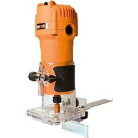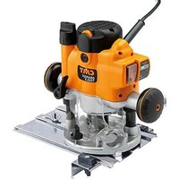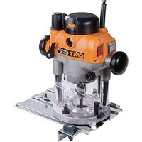
CMT7E - Milling machine CMT Orange Tools - Free user manual and instructions
Find the device manual for free CMT7E CMT Orange Tools in PDF.


User questions about CMT7E CMT Orange Tools
0 question about this device. Answer the ones you know or ask your own.
Ask a new question about this device
Download the instructions for your Milling machine in PDF format for free! Find your manual CMT7E - CMT Orange Tools and take your electronic device back in hand. On this page are published all the documents necessary for the use of your device. CMT7E by CMT Orange Tools.
USER MANUAL CMT7E CMT Orange Tools
natural_image
Two CMT Orange Tool machines on metal workstations, no visible text or symbols on the devices themselves.CMT7E
2400W Precision Router
OPERATING & SAFETY INSTRUCTIONS INSTRUCCIONES DE USO Y SEGURIDAD CONSIGNES D'UTILISATION ET DE SÉCURITÉ ISTRUZIONI OPERATIVE E DI SICUREZZA BEDIENUNGSANLEITUNG UND SICHERHEITSHINWEISE
natural_image
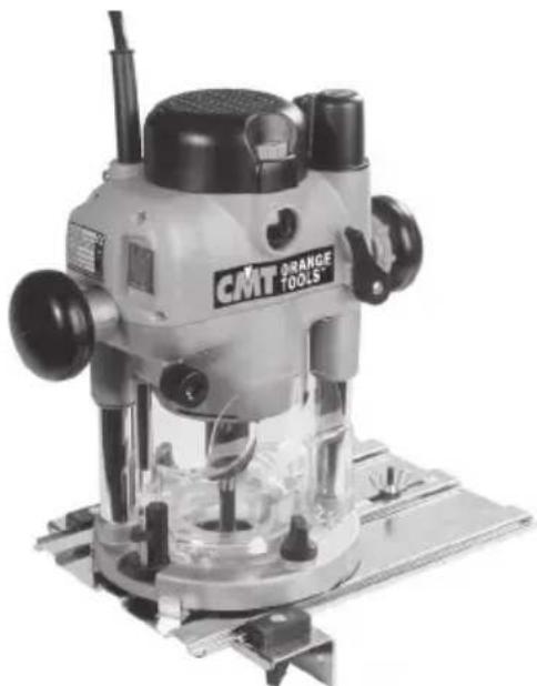
Exterior view of a CMT Orange Tool (no visible text or symbols on the device itself)
natural_image
R displayed machine with metal base and mounting bracket (no visible text or symbols)EN
OPERATING & SAFETY INSTRUCTIONS
Thank you for purchasing CMT 2400W / AC220\~240 / 50\~60Hz router.
IMPORTANT: This router has a number of unique features. Even if you are familiar with routers, please read this manual to make sure you get the full benefits of the unique design. Please keep this manual close to hand and ensure all users of this router have read and fully understand them.
ES
WARNING! Read and understand all instructions. Failure to follow all instructions listed below, may result in electric shock, fire and/or serious personal injury.
SAVE THESE INSTRUCTIONS
WORK AREA:
- Keep your work area clean and well lit. Cluttered benches and dark areas invite accidents.
- Do not operate the router in an environment where explosive or corrosive gases could be present. Power tools create sparks which may ignite fumes. and avoid areas where there is excessive dampness or humidity.
- Keep bystanders, children and visitors away while operating the router. Distractions can cause you to lose control.
ELECTRICAL SAFETY:
- If the plug does not fit fully in the outlet, reverse the plug. If it still does not fit, contact a qualified electrician to install a fit outlet. Do not change the plug in any way. Double insulation ☐ eliminates the need for the three wire grounded power cord and grounded power supply system.
- Avoid body contact with grounded surfaces such as pipes, radiators, ranges and refrigerators. There is an increased risk of electric shock if your body is grounded.
- Do not expose the router to wet conditions. Water entering the router will increase the risk of electric shock if your body is grounded.
- Do not abuse the power cord. Never use the cord to carry the router or to pull the plug from an outlet. Keep cord away from heat, oil, sharp edges or moving parts. Replace damaged cords immediately. Damaged cords increase the risk of electric shock.
- When operating a power tool outside, use an outdoor extension cord intended for outdoor use. It reduces the risk of electric shock.
PERSONAL SAFETY:
- Stay alert, watch what you are doing and use common sense when operating the router. Do not use the router while tired or under the influence of drugs, alcohol or medication. A moment of inattention while operating the router may result in serious personal injury.
- Dress properly. Do not wear loose clothing or jewellery. Contain long hair. Keep your hair, clothing and gloves away from moving parts. Loose clothes, jewellery, or long hair can be caught in moving parts.
- Avoid accidental starting. Be sure switch is off before plugging in. Plugging in the router with the switch on invites accidents.
- Remove the spanner before turning the router on. A spanner left attached to a rotating part may result in serious personal injury.
- Do not overreach. Keep proper footing and balance at all times. Proper footing and balance enables better control of the router in unexpected situations.
- Use safety equipment. Always wear eye protection. Dust mask, non-skid safety shoes, hard hat, or hearing protection must be used for appropriate conditions.
TOOL USE & CARE:
- Use clamps or other practical way to secure and support the workpiece to a stable platform. Holding the work by hand or against your body is unstable and may lead to loss of control.
- Do not force the router. Use the correct tool for your application. The correct tool will do the job better and safer at the rate for which it is designed.
- Do not use the router if switch does not turn it on or off. Any tool that cannot be controlled with the switch is dangerous and must be repaired. If there appears to be a problem refer to the “Trouble-shooting” and if necessary contact a repair centre.
- Disconnect the plug from the power source before making any adjustments, changing accessories, or storing the router. Such preventative safety measures reduce the risk of starting the tool accidentally.
- Store the router in a dry location, out of the reach of children and other untrained persons. This tool is dangerous in the hands of untrained users.
- Maintain tools with care. Keep cutting tools sharp and clean. Properly maintained tools, with sharp cutting edges are less likely to bind and are easier to control.
- Check for misalignment (ie. excessive vibration), binding of moving parts, or any damage that may affect the routers operation. If damaged have the tool serviced before using. Many accidents are caused by poorly maintained tools.
- Do not exceed the cutter manufacturers' rpm specifications.
- Never start the router while the cutter is touching the workpiece.
- Ensure the cutter has completely stopped before plunging to the collet lock position.
- Do not handle cutters immediately after use - they become very hot.
- Ensure the removable plunge spring is always fitted when using hand-held.
- Only use cutters and accessories specified as suitable for this router.
- Use only shank cutters with collet adaptor supplied.
SERVICE:
- Any damage to the router should be repaired and carefully inspected before use, by qualified repair personnel. Service or maintenance performed by unqualified personnel could result in a risk of injury.
- Servicing should only be carried out by authorised CMT Repair Centres using original CMT replacement parts. Follow instructions carefully and refer to “Trouble-shooting” for problem identification and advice. Use of unauthorised or faulty parts may create a risk of electric shock or injury.
SPECIFIC SAFETY RULES AND/OR SYMBOLS:
Hold the router by insulated gripping surfaces when performing an operation where the cutting tools may contact hidden wiring or its own cord. Contact with a “live” wire will make exposed metal parts of the tool “live” and shock the operator.
TROUBLESHOOTING
This chart contains information to assist in resolving router problems.
If a problem cannot be resolved using this advice do not tamper with the router - contact your local CMT branch for referral to your nearest authorised repair centre.
| SYMPTOM POSSIBLE CAUSE REMEDY | ||
| • Router will not operate • | No supply of powerBrushes worn or stickingSwitch is faultyMotor components open or short circuited | • Check that power is available at source• Disconnect power, open brush caps and ensure brushes move freely in the holders. Check whether the brushes require replacing, as shown on Page 10.• Contact Repair Centre• Contact Repair Centre |
| • Router runs slowly • | Blunt or damaged cutterVariable speed set lowMotor is overloaded | • Re-sharpen or replace cutterIncrease variable speed setting.Reduce pushing force on router. |
| • Makes an unusual sound • | Mechanical obstructionArmature has shorted sections | • Contact Repair Centre• Contact Repair Centre |
| • Excessive vibration • | Collet is loose.Bent cutter shank | • Tighten collet and ensure 1/4” collet adaptor (if fitted) is correctly installed.Replace cutter |
| • Heavy sparking occurs inside motor housing | Brushes not moving freelyArmature short circuited or open circuitedCommutator dirty | • Disconnect power, remove brushes, clean or replaceContact Repair Centre• Contact Repair Centre |
| • Micro adjuster tight or not winding | Plunge lock engagedPlunge selector in “Locked” position | • Release plunge lock leverSwitch plunge mode selector to “Unlock” Refer to “Handle Winder Plunge” |
| • Plunge lock lever not locking • | Plunge lock lever not correctly positioned | • Re-position plunge lock lever as described in “Free Plunge” |
| • Shutter on power switch not releasing | Router is plunged to full depth - in collet lock position | • Reduce plunge depth |
| • Can’t plunge to collet lock position | Power switch “On” • | Switch power “Off”. |
REDUCING COLLET
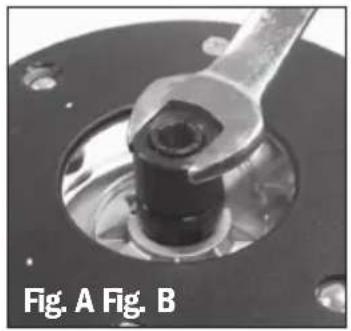
A second collet is supplied for the use of small shanked (eg. 1/4") cutters.
With the router in the collet lock position use the wrench to unscrew the standard collet, anticlockwise, and remove it from the router. Tighten the reduced collet in its place.
natural_image
Close-up of a mechanical component with a wrench inserted into a circular opening, labeled Fig. A and Fig. B (no other text or symbols)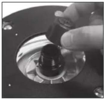
natural_image
Close-up of a hand turning a mechanical component with a black knob (no visible text or symbols)POWER SWITCH
When the router is connected to power the switch (b) will illuminate (in both "on" and "off" positions).
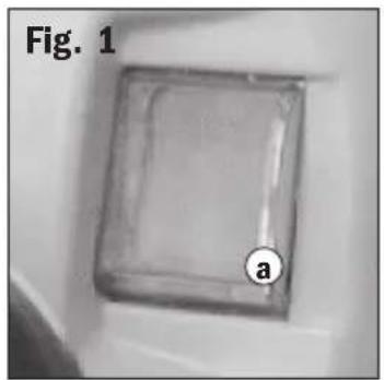
The clear switch shutter (a) prevents accidental starting of the router Fig. 1. It must be retracted before the router can be switched on. The cover will remain open until the router is switched off. Fig. 2.
natural_image
Close-up of a transparent square object with a labeled circular feature 'a' and figure label 'Fig. 1' (no other text or symbols)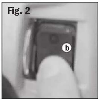
natural_image
Close-up of a mechanical component labeled 'b' with no visible text or symbols beyond the label 'Fig. 2'VARIABLE SPEED CONTROL
The router speed should be adjusted according to cutter size. The highest setting is suitable for regular sized cutters, whereas large cutters require a lower setting. Speed should also be reduced if burn marks appear on the workpiece.
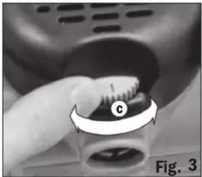
The Speed Control (c) is marked 1 to 5, corresponding approximately with the speeds shown below.
| Setting | rpm |
| 1 | 8,000 |
| 2 | 10,000 |
| 3 | 14,000 |
| 4 | 18,000 |
| 5 | 20,000 |
Turn the dial to select the desired speed. Fig. 3
natural_image
Close-up of a hand pressing a button on a mechanical component, labeled 'Fig. 3' (no readable text or symbols beyond label)DUST EXTRACTION
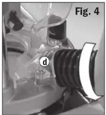
The CMT Router is equipped with a Dust Port (d) for effective chip extraction. It accepts 38mm (1-1/2") O.D. hose. The hose screws into position via a left hand thread (anti-clockwise). Fig. 4
natural_image
Close-up of a mechanical component with a threaded spring and labeled part (d), no readable text or symbols present.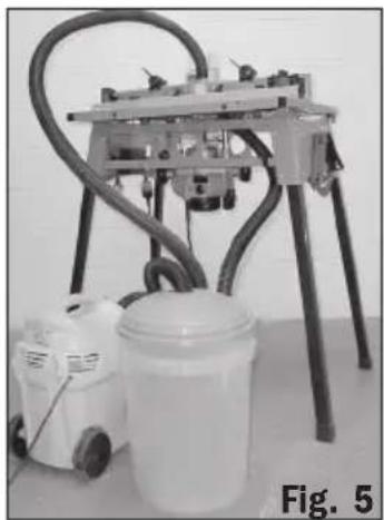
natural_image
Laboratory setup with a mounted machine and a white container, labeled Fig. 5 (no visible text or symbols on equipment)CUT DEPTH ADJUSTMENT
There are three methods of cut depth adjustment, depending on the accuracy and control required: Free Plunge, for conventional & fast depth setting; Handle Winder Plunge, for controlled & fast adjustment; and Micro Adjuster, for precise depth setting throughout the full plunge range.
FREE PLUNGE
- Free plunge depth adjustments can be made with the Plunge Mode Selector button engaged. Press it deep inside the handle until it engages inward Fig 6.
- Release the Plunge Lock Lever (g). Push the body of the router until the desired depth is reached. Re-lock the plunge lock lever.
Note: The position of the plunge lock lever can be altered by removing its retaining screw and repositioning the lever on the bolt. Re-tighten firmly.

natural_image
Close-up of a finger pressing a black circular component on a mechanical device (no visible text or symbols)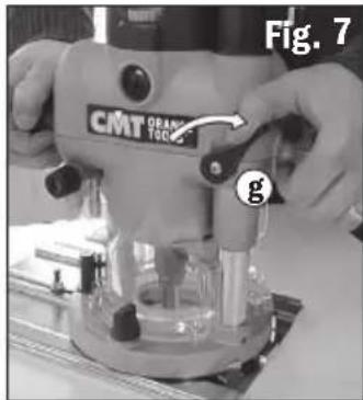
text_image
Fig. 7 CMT ORANGE TOTS gHANDLE WINDER PLUNGE
- Handle Winder Plunge depth adjustments can be made when the plunge mode selector button is flush with the handle. If engaged, press the Plunge Mode Selector button inward and allow it to spring out flush with the handle. Ensure the Plunge Lock Lever is unlocked Fig 8.
- Pull the Winder Handle Clutch Ring into the handle then turn the handle to raise or lower the cutter. Release the ring at the required depth, allowing it to "pop out", locking the cutter at the desired depth Fig 9.
- Lock the plunge lever, particularly for heavy cuts.
MICRO ADJUSTER -
For use in the Handle Winder Plunge Mode only.
- Disengage the Plunge Mode Selector button, and ensure that the plunge lock lever is unlocked Fig 10a.
Note: If the micro winder is turned with the plunge lock lever engaged the micro winder will start clicking and the cut depth will remain unchanged.
- Turn the Micro Winder Adjuster Knob clockwise to increase cut depth and anti-clockwise to reduce cut depth Fig 10b.
Note: When the end of the depth adjustment range is reached the micro winder will offer greater resistance to turn and will begin to "click".
- Lock the plunge lever, particularly for heavy cuts.
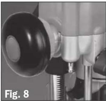
natural_image
Close-up of a mechanical component with a black circular head and threaded shaft, labeled 'Fig. 8' (no readable text or symbols)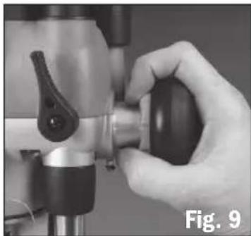
natural_image
Close-up of a hand operating a mechanical tool with a black handle (no visible text or symbols)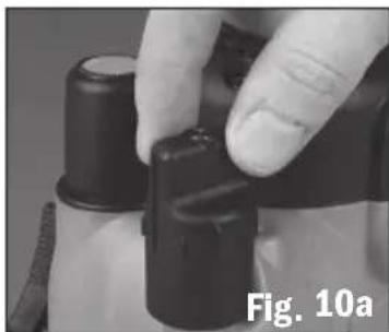
natural_image
Close-up of a hand adjusting black plastic components, labeled Fig. 10a (no text on the objects themselves)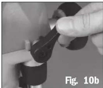
natural_image
Close-up of hands adjusting a mechanical component (no visible text or symbols)MISE EN PLACE ET REMPLACEMENT DES FRAISES
- Turn the power switch (b) "off", allowing the switch shutter (a) to close (Fig. 1). (The shutter will lock closed when the collet lock is engaged.)
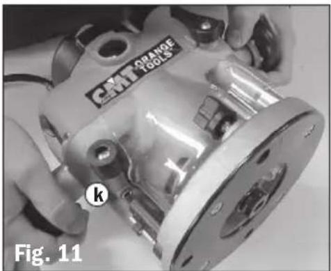
- Wait until the cutter has completely stopped spinning then plunge the router to its maximum depth using the free plunge or winder handle plunge mode. Fig. 11. Note: ensure the depth stop (k) is released (see Fig. 13 below). The collet should now protrude through the base (and the CMT Router Table if fitted), allowing easy spanner access.
- Use the spanner (j) supplied to turn the collet slightly, allowing the collet lock to engage. Once engaged, turn the spanner anticlockwise to release, or clockwise to tighten the cutter. Fig. 12.
Note: When fitting cutters, ensure the shank is inserted fully into the collet. - Return the router to a normal operating depth. This will disengage the collet lock and release the switch shutter, enabling access to the power switch.
natural_image
Close-up of a metallic automotive component being handled, labeled 'CMT ORANGE TOOLS' and marked with 'k', no readable text or symbols beyond labels.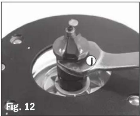
natural_image
Close-up of a mechanical component with a labeled part (i) and label 'Fig. 12' (no readable text or symbols beyond labels)Cut depth can be accurately preset using the Depth Stop (k) and Turret (l) in the free plunge mode.
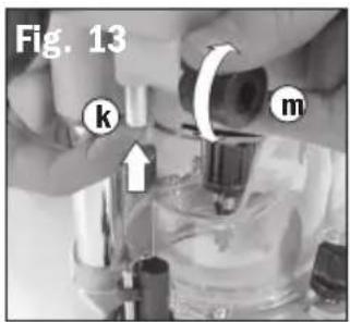
- Loosen the Depth Stop Lock (m) and retract the depth stop fully, then re-tighten. Fig. 13.
- Set the Turret Thumbwheel(s) (n) to the desired plunge depth(s) using the scales on the turret post. Fig. 14.
- Fit the cutter, and adjust the plunge depth until the cutter tip is level with your "zero datum" (eg. router base or Router Table surface). Fig. 15.
- Rotate the turret until the fixed turret post is in line with the depth stop. Release the stop, allowing it to spring onto the post, then re-tighten. Fig. 16.
-
Rotate the turret again until the bolt of the required thumbwheel is in line with the stop. Fig.
-
Plunge until the hollow depth stop locates over the bolt and hits the thumbwheel. Engage the plunge lock lever (g).
Note: the plunge depth must be reduced before the turret can be rotated to another stop position.
text_image
Fig. 13 k m
text_image
Fig. 14 n l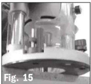
natural_image
Close-up of a mechanical component with metallic parts and a circular base, labeled 'Fig. 15' (no readable text or symbols on the main subject)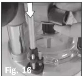
natural_image
Close-up of a mechanical device with a metallic rod and lever, labeled 'Fig. 16' (no readable text or symbols)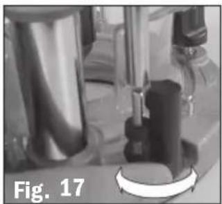
natural_image
Close-up of laboratory glassware with a circular component, labeled 'Fig. 17' (no readable text or symbols on the main subject)HAND-HELD OPERATION
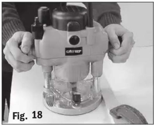
- Always use both hands to control the router and ensure your workpiece is securely clamped to prevent any movement during operation. Fig. 18.
- Never operate the router free-hand without some form of guidance. Guidance can be provided by a bearing guided cutter, the fence guide supplied or a straight edge (eg. a batten clamped to your work as shown in Fig. 18).
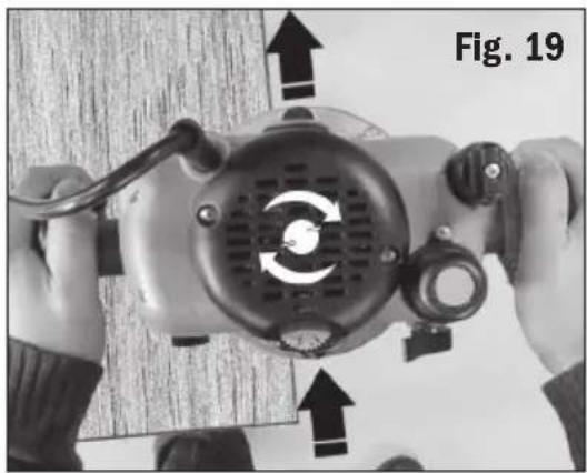
- Always feed against the direction of cutter rotation (clockwise, as indicated by the arrows on the router base). Fig. 19.
- Do not operate the router upside down unless securely mounted in a well guarded router table (eg. CMT brand).
natural_image
Person operating a CRTRD-printed machine with hands adjusting components (no visible text or symbols)THE BASE ASSEMBLY
The Base (o) supplied with the CMT Router can be used as an extended baseplate, as a fence or as a circle cutter.
FITTING THE FENCE
- Loosen the Mounting Knobs (p) until they are approximately 10mm (3/8") above the base of the router.
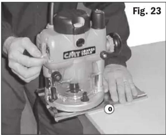
- Position the router inside the tabs on the Base (o), with the knobs above the two keyhole slots. Note: the router can be mounted with the long overhang to the left or to the right depending on where the support is required. For edge work, locate the power switch on the short overhang side of the base, as shown in Fig. 23.
- Push down on the mounting knobs until the bolt heads locate into the keyholes, then slide the router until it sits against the locating tabs. Fig. 21. Tighten the knobs firmly.
- Loosen the Fence Knobs (q) a few turns and slide the Fence (r) onto the base from the chosen end. Fig. 22. Lock at the desired setting by tightening both fence knobs.
natural_image
Close-up of hands holding a mechanical device with directional arrows indicating motion or force (no text or symbols on the device itself)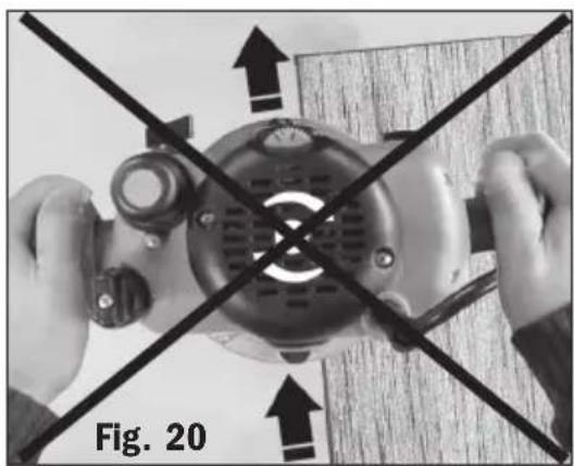
natural_image
Top-down view of hands operating a mechanical device with cross-sectional lines, labeled Fig. 20 (no text or symbols on the device itself)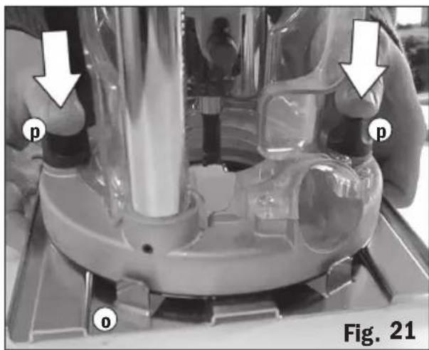
natural_image
Close-up of a mechanical device with labeled parts (p, o) and directional arrows, no readable text or symbols beyond labels
text_image
q r q Fig. 22USING THE FENCE
Extended Base
The fence base (o) provides greater stability when using bearing guided cutters along an edge. The fence (r) is not used for these cuts.
Place one hand on the long end of the base, holding it down onto your work, and grip the router handle, furthest away, with your other hand. Fig. 23. Note: position the router with the power switch closest to your right hand.
Fence
Fit the Fence (r) to the short end of the base (o) for use when performing edge work with a non-bearing cutter. Use the hand positions shown in Fig. 23.
When routing trenches some distance in from an edge, fit the fence to the long end of the base. Fig. 24.
If using a very large diameter cutter it may be necessary to fix wooden blocks to the fence faces via the screw holes, to ensure the cutter does not contact the fence.
Circle Cutter
- Fit the base (o) (without the fence) to the router.
- Remove the Pivot Mount (s) from the base and fix it to the centre of your work using a small nail or screw through one of the small holes provided. Fig. 25. Leave the bolt fitted through the pivot mount.
- Position the router and base over the pivot mount and refit the washer and wing-nut.
With the power switched "Off", rotate the router along the intended path to check the circle, and make any necessary adjustments.
- Cut the circle in several passes, lowering the cut depth by say 2mm (1/16") each pass. Do not attempt to cut deeply in one pass.
Through cuts: If cutting all the way through the material, fix a sacrificial board to the underneath of your workpiece. Fig. 26. Cut the circle oversize, then when the cut is all the way through, reduce the diameter and work back to the desired size, using light, full depth passes.
natural_image
Person using a CMT orange tool on a workbench, no visible text or symbols on the device itself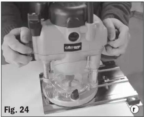
natural_image
Person operating a precision machine on a workbench, labeled Fig. 24 (no visible text or symbols on the machine itself)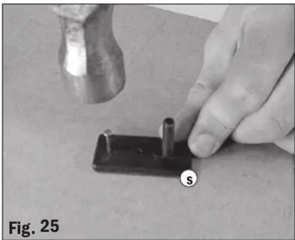
natural_image
Close-up of a hand using a hammer to apply a small mechanical component, labeled 'Fig. 25' (no text on the object itself)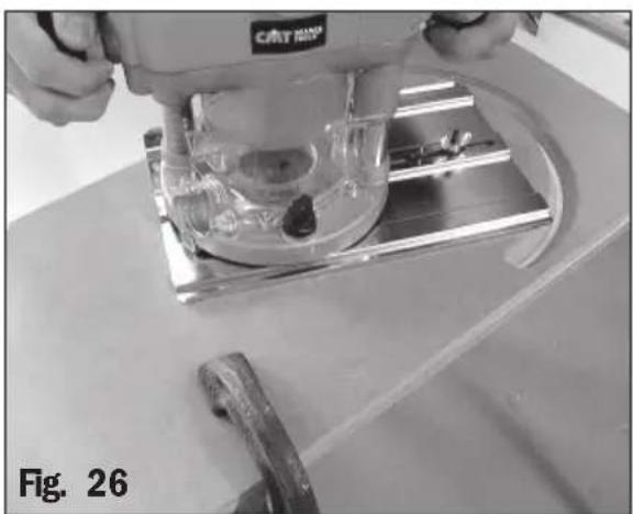
natural_image
Close-up of a CNC machine tool operating on a workbench, no visible text or symbols- Fitting and operating this router on a CMT Router Table should be done in accordance to the literature supplied with your Router Table.
While the CMT Router was designed for efficient and convenient operation on most router tables, it is particularly suited to CMT brand tables.
Router adjustments are made extremely easy using the unique features described earlier in the manual. Refer to "Fitting & Changing Cutters" and "Cut Depth Adjustment".
INSTALLING THE PLUNGE SPRING
The plunge spring is supplied as an accessory in the router pack. The plunge spring is designed to be used when utilising the plunge router feature.
- Set the router to the top of the plunge range and engage the plunge lock lever.
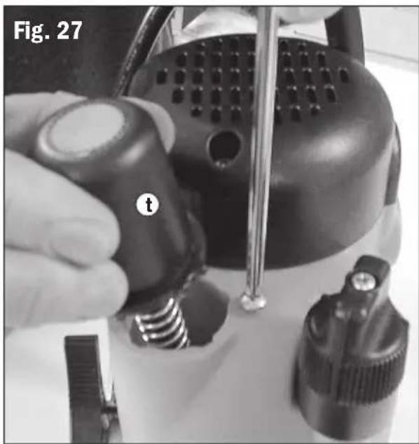
- Loosen the small screw (anti-clockwise) next to the plunge spring cap (t) in a few turns. Twist the cap slightly anti-clockwise to remove it.
- Slide the spring through the spigot on the Plunge Spring Cap and place into the entry point for the spring.
- Apply sufficient force and hold firmly the plunge spring cap to push the spring down and lock the plunge spring cap under the screw.
- Re-tighten the screw in a clockwise direction when in position.
REMOVING THE PLUNGE SPRING
- Set the router to the top of its plunge range and engage the plunge lock lever.
- Loosen the small screw next to the Plunge Spring Cap (t) a few turns. Twist the cap slightly anti-clockwise to remove it. Fig. 27. Note: hold the cap firmly while releasing tension from the spring.
- Remove the spring and store in a safe place.
- Replace the plunge spring cap and re-tighten the screw.
WARNING: Only remove the plunge spring when fitted beneath a router table. Ensure it is always fitted for hand-held use.
natural_image
Close-up of a hand using a tool to adjust a mechanical component, labeled 't' and part number '27' (no readable text beyond labels)TABLE WINDER
- Mount the router securely into your router table as detailed in your router table instructions. Turn the table (with router fitted) upside down.
- With a marker pen trace the scallop in the base of the router onto the underneath of your router table. Complete the tracing to form a circle approximately 12.7mm (1/2") diameter.
- Remove the router and drill a pilot hole through the centre of your circle. Using a 12.7mm (1/2") bit drill your final access hole.
WARNING:
File off any rough burrs using a round file.
- Refit the router and turn the router table right way up.
- Fit the table winder handle (N) through the hole in the tabletop and push it onto the routers winder mechanism.
natural_image
Close-up of a gloved hand using a microscope on a workbench, no visible text or symbols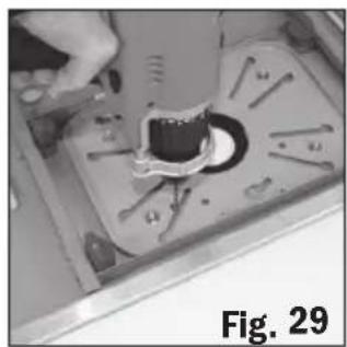
natural_image
Close-up of a mechanical component with a central hole and surrounding pins, labeled Fig. 29 (no readable text or symbols)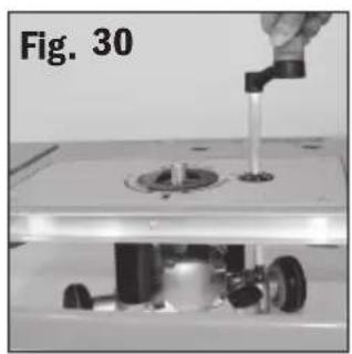
natural_image
Close-up of a mechanical assembly with a tool inserted into a mold, no visible text or symbols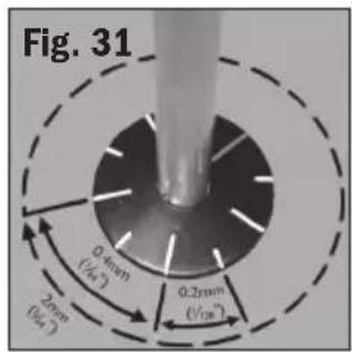
text_image
Fig. 31 0.4mm (√4.5) 2mm (√4.5) 0.2mm (√12m)WARNING: If necessary extend your hole using a round file.
- Release the plunge lock lever and use the winder handle to set your cut depth.
CALIBRATION MARKS:
Each line on the winder wheel represents 0.2mm (1/128") cut depth increments. A full 360 degree turn is equal to a 2mm (3/32") depth adjustment.
- Re-lock the plunge lock lever and commence your work.
BRUSH REPLACEMENT
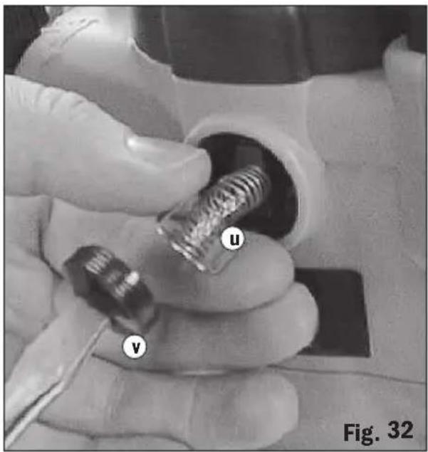
The carbon brushes (u) are a consumable item which should be inspected periodically and replaced when worn.
- With the router disconnected from power, unscrew the Brush Caps (v) located on the front and rear of the motor.
- Remove the brushes by pulling carefully on the protruding springs. Fig. 32.
- If either of the brushes (u) is worn to less than 6mm (1/4") long, they must both be replaced using genuine CMT replacement brushes - available from Authorised CMT Repair Centres.
CMT will not be responsible for any damage or injury caused by unauthorised repair of the router or by mishandling of the tool.
text_image
Fig. 32natural_image
Close-up of a mechanical component with a wrench and central bore (no visible text or symbols)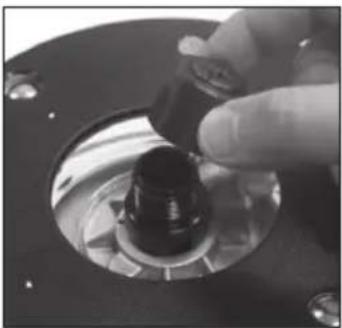
natural_image
Close-up of a hand pressing a button on a mechanical component (no visible text or symbols)INTERRUPTOR DE POTENCIA
natural_image
Close-up of a transparent square object with a labeled circular feature 'a' and figure label 'Fig. 1' (no other text or symbols)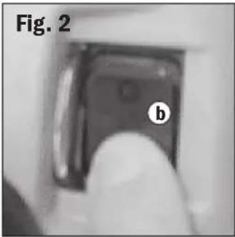
natural_image
Close-up of a mechanical component with labeled part 'b' and figure label 'Fig. 2' (no other text or symbols)CONTROL VARIABLE DE VELOCIDAD
natural_image
Close-up of a hand pressing a button on a mechanical component, labeled 'Fig. 3' (no readable text or symbols beyond label)EXTRACCIÓN DE POLVO
natural_image
Close-up of a mechanical component with a threaded fitting and labeled part 'd' (no readable text or symbols beyond label)
natural_image
Mechanical setup with a mounted machine and two small containers, labeled 'Fig. 5' (no readable text or symbols on the equipment itself)AJUSTE DE LA PROFUNDIDAD DE CORTE
natural_image
Close-up of a finger pressing a black circular component on a mechanical device (no visible text or symbols)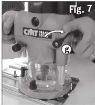
text_image
Fig. 7 CMT ORANGE TOCO gPROFUNDIDAD MANUAL A MANIVELA
natural_image
Close-up of a mechanical component with a black circular head and threaded shaft, labeled 'Fig. 8' (no readable text or symbols)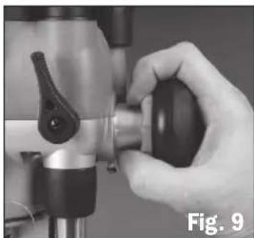
natural_image
Close-up of a hand operating a mechanical device with a black handle (no visible text or symbols)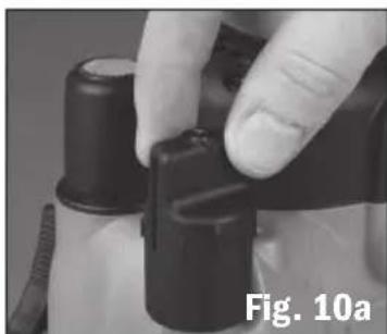
natural_image
Close-up of a hand adjusting a black and white mechanical component (no visible text or symbols)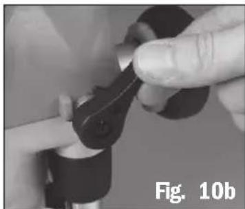
natural_image
Close-up of hands adjusting a mechanical component (no visible text or symbols)natural_image
Close-up of a metallic cylindrical mechanical component with hands holding it, labeled 'CMT ORANGE TOOLS' and marked 'k', shown in black-and-white (no readable text beyond labels)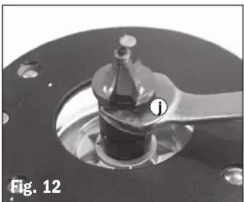
natural_image
Close-up of a mechanical component with a labeled part (i) and label 'Fig. 12' (no readable text or symbols beyond labels)TOPE DE PROFUNDIDAD Y TORRE
natural_image
Close-up of a mechanical component with metallic parts and a circular base, labeled 'Fig. 15' (no readable text or symbols on the main subject)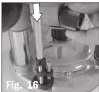
natural_image
Close-up of a mechanical device with a metallic rod and lever, labeled Fig. 16 (no readable text or symbols)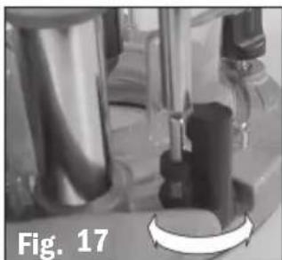
natural_image
Close-up of a mechanical device with a circular component, labeled 'Fig. 17' (no readable text or symbols on the device itself)USO MANUAL
natural_image
Person operating a mounted machine with visible wiring and components (no text or symbols)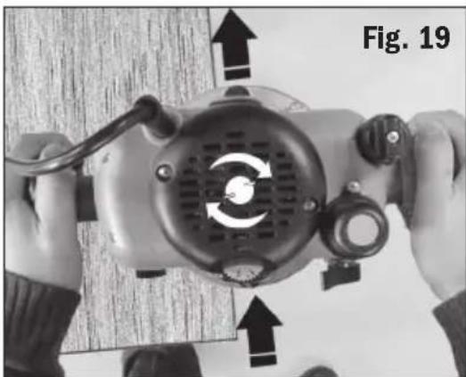
natural_image
Close-up of hands operating a mechanical device with visible internal components and directional arrows (no text or symbols)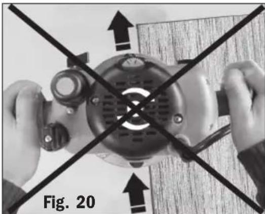
natural_image
Close-up of hands operating a mechanical device with crossed black lines indicating alignment or disassembly (no text or symbols visible)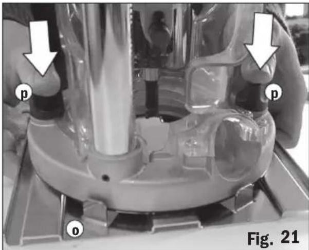
natural_image
Close-up of a mechanical device with labeled parts (p, o) and directional arrows, no readable text or symbols beyond labels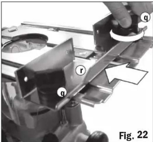
text_image
q r q Fig. 22USO DE LA GUÍA
Base extendida
natural_image
Person using a CMT orange tools machine on a workbench, no visible text or symbols on the device itself.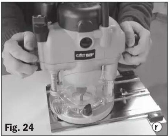
natural_image
Person operating a precision machine on a workbench, labeled Fig. 24 (no visible text or symbols on the machine itself)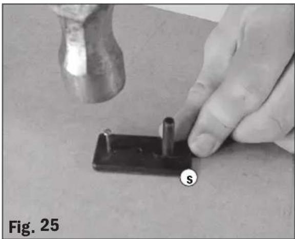
natural_image
Close-up of a hand using a hammer to apply a small mechanical component labeled 'S', with no visible text or symbols on the object itself.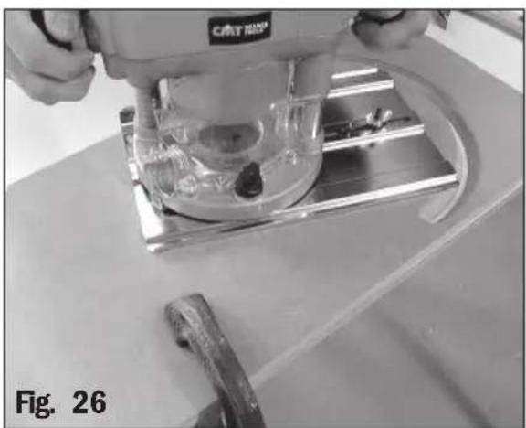
natural_image
Close-up of a CNC machine tool operating on a workbench, no visible text or symbolsUSO MONTADO EN LA MESA
natural_image
Close-up of a hand using a screwdriver to adjust a small component, with no visible text or symbols.MANIJA ROTATIVA DE MESA
natural_image
Close-up of hands using a microscope and computer mouse on a workbench, no visible text or symbols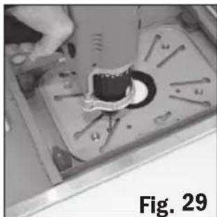
natural_image
Close-up of a mechanical component with a central hole and surrounding screws, labeled Fig. 29 (no text or symbols on the main subject)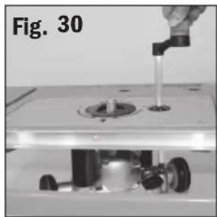
natural_image
Mechanical assembly showing a tool interacting with a workbench, no visible text or symbols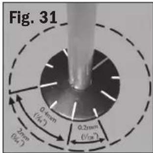
text_image
Fig. 31 0.4mm (√4.4) 2mm (√4.4) 0.2mm (√28°)natural_image
Close-up of a mechanical component with a wrench inserted into a circular opening, labeled Fig. A and Fig. B (no other text or symbols)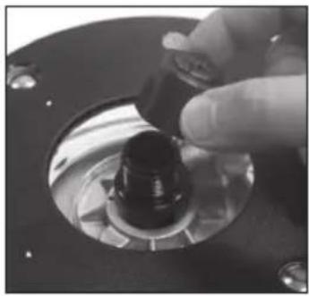
natural_image
Close-up of a hand turning a mechanical component with a black knob (no visible text or symbols)INTERRUPTEUR D'ALIMENTATION
natural_image
Close-up of a transparent square object with a labeled circular feature 'a' and figure label 'Fig. 1' (no other text or symbols)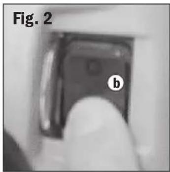
natural_image
Close-up of a mechanical component labeled 'b' with no visible text or symbols beyond the label 'Fig. 2'COMMANDE DE VITESSE VARIABLE
natural_image
Close-up of a hand pressing a button on a mechanical component, labeled 'C' and 'Fig. 3' (no readable text or symbols beyond labels)EXTRACTION DE LA SCIURE
natural_image
Close-up of a mechanical component with a threaded spring and labeled part (d), no readable text or symbols present.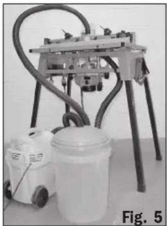
natural_image
Mechanical setup with a mounted device and a white container, labeled 'Fig. 5' (no text or symbols on the equipment itself)RÉGLAGE DE LA PROFONDEUR DE COUPE
natural_image
Close-up of a hand pressing a black circular component on a mechanical device (no visible text or symbols)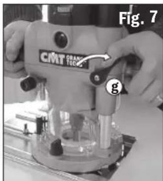
text_image
Fig. 7 CMT ORANGE TECHNOLOGY gRÉGLAGE DE PLONGÉE AVEC LA POIGNÉE D'ARMEMENT
natural_image
Close-up of a mechanical component with a black circular head and threaded shaft, labeled 'Fig. 8' (no readable text or symbols)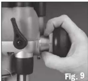
natural_image
Close-up of a hand operating a mechanical tool with a handle, labeled 'Fig. 9' (no text on the tool itself)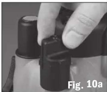
natural_image
Close-up of a hand adjusting a black and white plastic component (no visible text or symbols)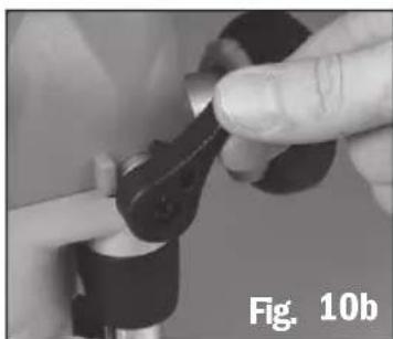
natural_image
Close-up of a hand adjusting a mechanical component (no visible text or symbols)RÉGLAGE DE LA PROFONDEUR DE COUPE
natural_image
Close-up of a metallic industrial component with hands holding it, labeled 'CMT ORANGE TOOLS' and marked 'k', no readable text or symbols beyond labels.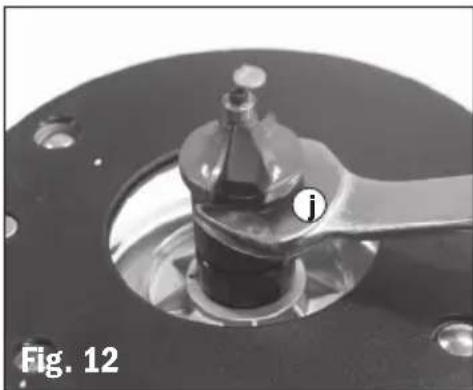
natural_image
Close-up of a mechanical component with a handle and central hub, labeled 'Fig. 12' (no readable text or symbols beyond label)MISE EN PLACE ET REMPLACEMENT DES FRAISES
natural_image
Close-up of a mechanical component with metallic parts and a circular base, labeled 'Fig. 15' (no readable text or symbols on the main subject)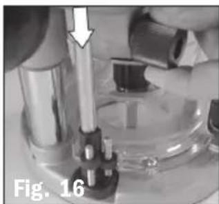
natural_image
Close-up of a mechanical device with a metallic rod inserted, labeled Fig. 16 (no visible text or symbols on the device itself)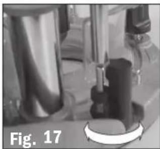
natural_image
Close-up of laboratory glassware with a central mechanical component, labeled 'Fig. 17' (no other text or symbols visible)UTILISATION À MAIN LEVÉE
natural_image
Person operating a Centrex CNC machine on a workbench, no visible text or symbols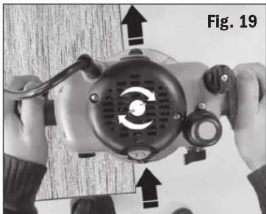
natural_image
Close-up of hands operating a mechanical device with directional arrows indicating motion or rotation (no text or symbols on the device itself)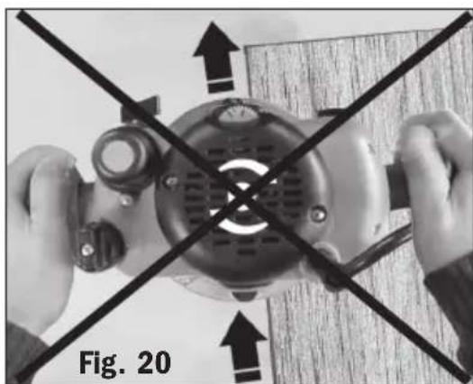
natural_image
Close-up of hands operating a mechanical device with crossed lines indicating alignment or disconnection (no text or symbols visible)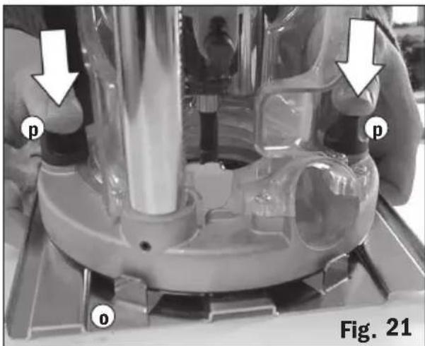
text_image
p o p Fig. 21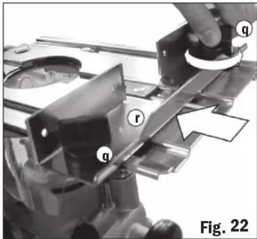
text_image
q r q Fig. 22UTILISATION DU GUIDE
Base élargie
natural_image
Person using a CMT orange tools machine on a workbench, no visible text or symbols on the device itself.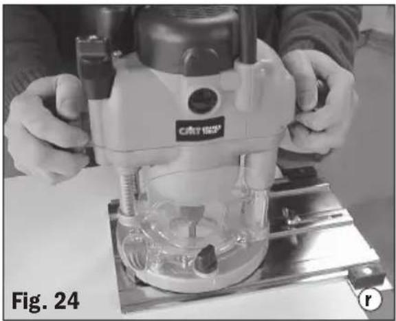
natural_image
Person operating a precision machine on a workbench, labeled Fig. 24 (no visible text or symbols on the machine itself)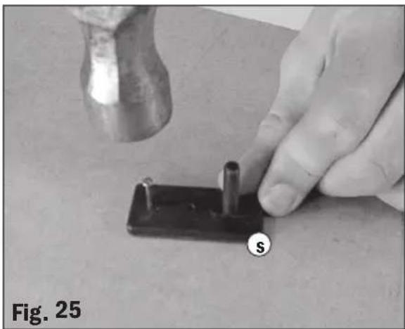
natural_image
Close-up of a hand using a hammer to apply a small component labeled 'S' on a surface, with no visible text or symbols beyond the label.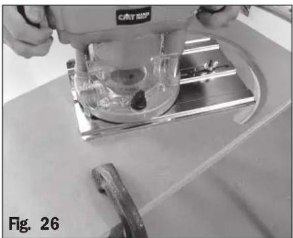
natural_image
Close-up of a CNC machine tool operating on a workbench, no visible text or symbolsUTILISATION DE LA DÉFONCEUSE MONTÉE SOUS TABLE
INSTALLATION DU RESSORT DE PLONGÉE
natural_image
Close-up of hands using a microscope and power supply on a lab bench (no visible text or symbols)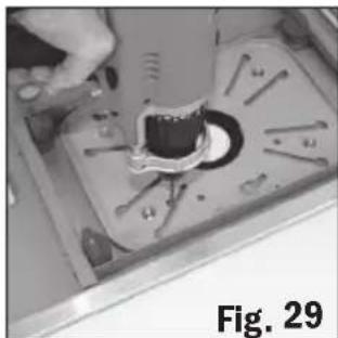
natural_image
Close-up of a mechanical component with a central hole and surrounding parts, labeled Fig. 29 (no readable text or symbols)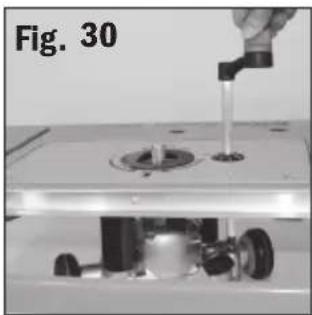
natural_image
Close-up of a mechanical device with a hand holding a tool, showing internal components and a circular base (no text or symbols visible)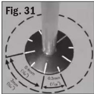
text_image
Fig. 31 0.4mm (1/4°) 2.6mm (1/4°) 0.2mm (1/20°)natural_image
Close-up of a mechanical component with a wrench inserted into a circular opening, labeled Fig. A and Fig. B (no other text or symbols)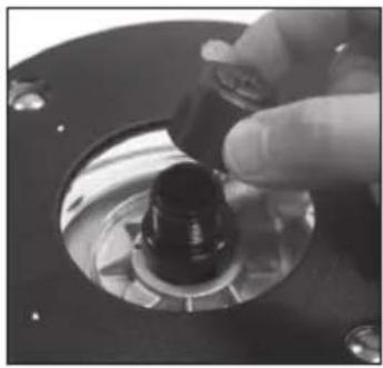
natural_image
Close-up of a hand turning a mechanical component with a black knob (no visible text or symbols)INTERRUTTORE
natural_image
Close-up of a transparent square object with a labeled point 'a' and figure label 'Fig. 1' (no other text or symbols)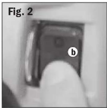
natural_image
Close-up of a mechanical component labeled 'b' with no visible text or symbols beyond the label 'Fig. 2'CONTROLLO DI VELOCITÀ VARIABILE
natural_image
Close-up of a hand pressing a button on a mechanical component, labeled 'Fig. 3' (no readable text or symbols beyond label)ASPIRAZIONE POLVERE
natural_image
Close-up of a mechanical component with a labeled section 'd' and 'Fig. 4' (no readable text or symbols beyond label)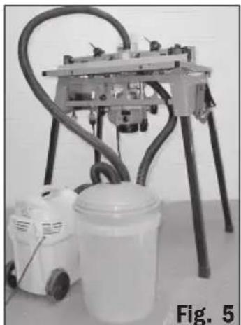
natural_image
Laboratory setup with a mounted machine and a bucket, labeled Fig. 5 (no visible text or symbols on equipment)natural_image
Close-up of a finger pressing a black circular component on a mechanical device (no visible text or symbols)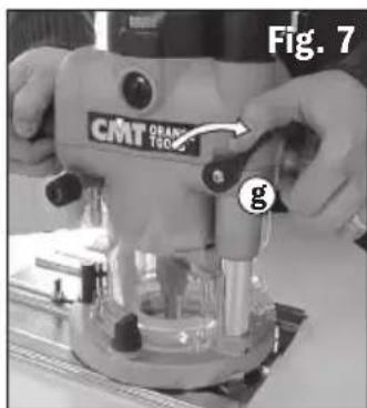
text_image
Fig. 7 CMT ORANGE TICKER gAFFONDO CON IMPUGNATURA GIREVOLE
natural_image
Close-up of a mechanical device with a black circular component and metallic pins (no visible text or symbols)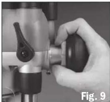
natural_image
Close-up of a hand operating a mechanical tool with a black handle (no visible text or symbols)
natural_image
Close-up of a hand adjusting a black plastic component, labeled Fig. 10a (no text on the object itself)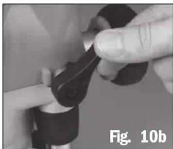
natural_image
Close-up of hands adjusting a mechanical component (no visible text or symbols)MONTARE E CAMBIARE LE FRESE
natural_image
Close-up of a metallic cylindrical mechanical component with hands holding it, labeled 'CMT ORANGE TOOLS' and marked 'k', no readable text or symbols beyond labels.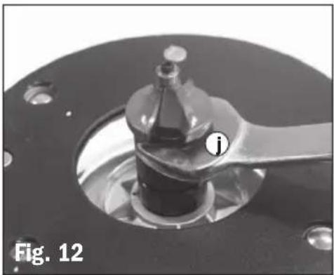
natural_image
Close-up of a mechanical component with a labeled part (i) and label 'Fig. 12' (no readable text or symbols beyond labels)BLOCCO PROFONDITÀ E TORRETTA
natural_image
Close-up of a mechanical component with metallic parts and a circular base, labeled 'Fig. 15' (no readable text or symbols on the main subject)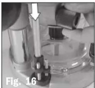
natural_image
Close-up of a mechanical device with a metallic rod and lever, labeled 'Fig. 16' (no readable text or symbols)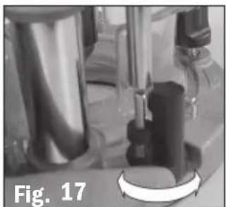
natural_image
Close-up of mechanical components with no visible text or symbolsnatural_image
Person operating a CATROP electric drill press machine on a workbench (no visible text or symbols)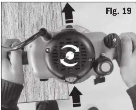
natural_image
Close-up of hands operating a mechanical device with visible internal components and directional arrows (no text or symbols)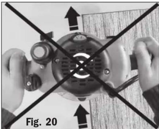
natural_image
Close-up of hands operating a mechanical device with crossed black lines indicating alignment or disconnection (no text or symbols visible)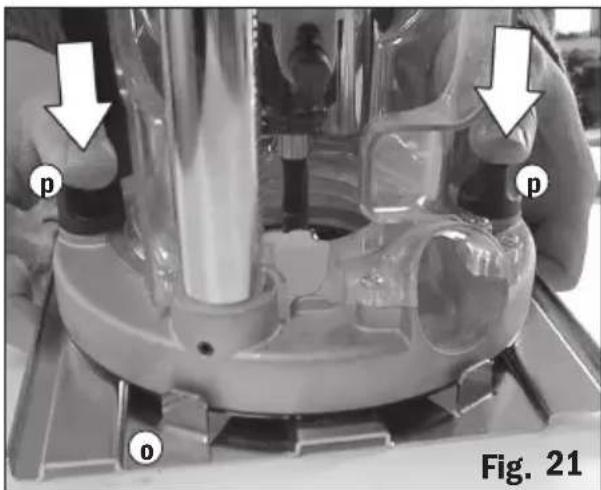
text_image
p o p Fig. 21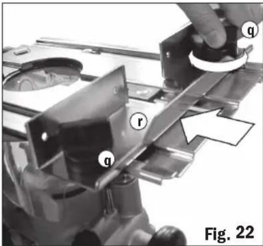
text_image
q r q Fig. 22UTILIZZO DELLA GUIDA DIRITTA
Base estesa
natural_image
Person using a CMT orange tools machine on a workbench, no visible text or symbols on the device itself.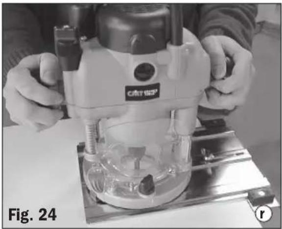
natural_image
Person operating a precision machine on a workbench, labeled Fig. 24 (no visible text or symbols on the machine itself)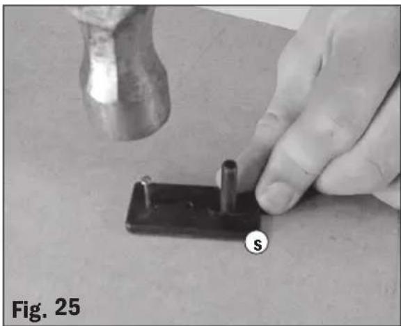
natural_image
Close-up of a hand using a hammer to apply a small mechanical component labeled 'S', with no visible text or symbols on the object itself.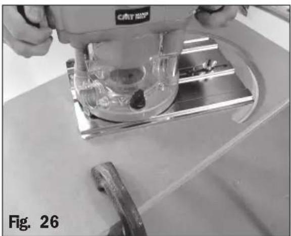
natural_image
Close-up of a CNC machine tool operating on a workbench, no visible text or symbolsnatural_image
Close-up of a gloved hand using a power tool on a lab bench, with mechanical components and a magnifying glass (no visible text or symbols)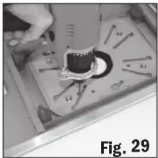
natural_image
Close-up of a mechanical component with a central hole and surrounding pins, labeled Fig. 29 (no readable text or symbols)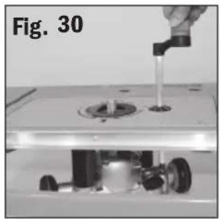
natural_image
Close-up of a mechanical device with a hand holding a small object, labeled 'Fig. 30' (no readable text or symbols on the object itself)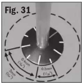
text_image
Fig. 31 0.4mm (1/4") 2mm (0/4) 0.2mm (1/2m)natural_image
Close-up of a mechanical component with a wrench and central bore (no visible text or symbols)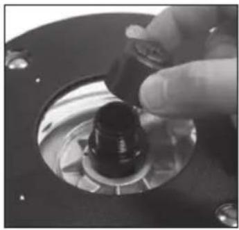
natural_image
Close-up of a hand turning a mechanical component with a black knob (no visible text or symbols)HAUPTSCHALTER
natural_image
Close-up of a hand pressing down on a mechanical component, labeled 'C' and 'Abb. 3' (no readable text or symbols beyond labels)STAUBABZUG
natural_image
Close-up of a mechanical component with a labeled section (d) and label 'Abb. 4' (no readable text or symbols beyond labels)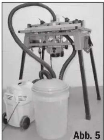
natural_image
Laboratory setup with a vacuum cleaner and a bucket on a table, labeled Abb. 5 (no visible text or symbols on equipment)natural_image
Close-up of a hand pressing a black circular component on a mechanical device (no visible text or symbols)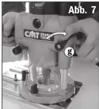
text_image
Abb. 7 CMT ORANGE TSCS gnatural_image
Close-up of a mechanical component with a black circular head and threaded shaft, labeled 'Abb. 8' (no other text or symbols visible)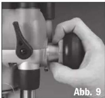
natural_image
Close-up of a hand operating a mechanical tool with a black handle (no visible text or symbols)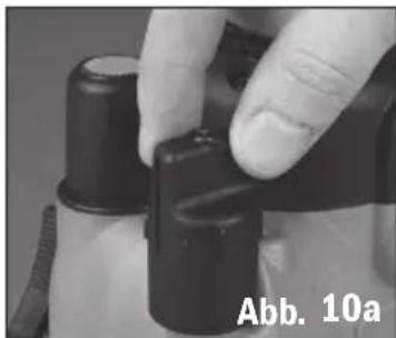
natural_image
Close-up of a hand adjusting a black mechanical component, labeled 'Abb. 10a' (no other text or symbols visible)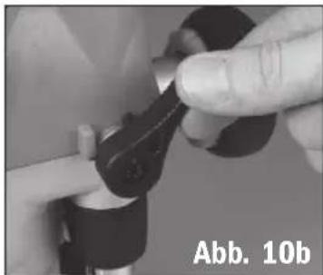
natural_image
Close-up of hands adjusting a mechanical component (no visible text or symbols)EINSETZEN UND WECHSELN DER FRÄSER
natural_image
Close-up of a mechanical component with a handle and central shaft, labeled 'Abb. 12' (no readable text or symbols beyond label)natural_image
Close-up of a mechanical component with metallic parts and a circular base, labeled Abb. 15 (no readable text or symbols)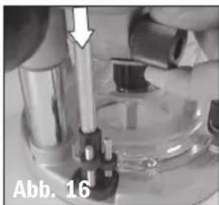
natural_image
Close-up of a mechanical device with a tool and component, labeled Abb. 16 (no readable text or symbols)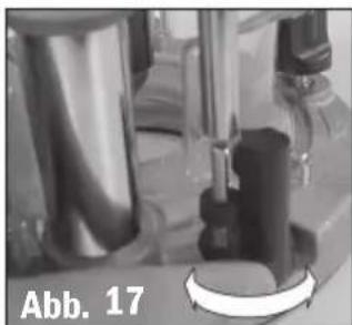
natural_image
Close-up of a mechanical device with a black component and a white circular button, labeled 'Abb. 17' (no readable text or symbols on the device itself)natural_image
Person operating a CRTRD printing press machine with mechanical components (no visible text or symbols)DIE GRUNDPLATTE
natural_image
Close-up of hands holding a mechanical device with directional arrows indicating motion or movement (no text or symbols on the device itself)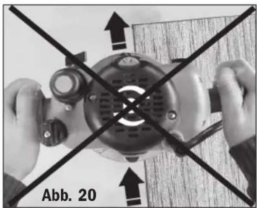
natural_image
Top-down view of hands operating a mechanical device with cross-bracing arrows, labeled 'Abb. 20' (no readable text or symbols on the device itself)Grundplatte.
natural_image
Person operating a precision machine on a workbench, no visible text or symbols in the image.Rundschneider
natural_image
Close-up of a hand using a hammer to press a small black component labeled 's' on a surface, with no visible text or symbols beyond the label.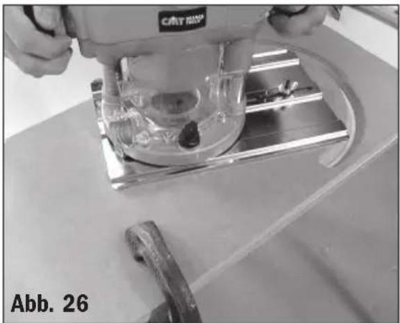
natural_image
Close-up of a metal cutting machine tool operating on a workbench, with no visible text or symbols.natural_image
Close-up of a mechanical device with a tool and clamped components, labeled Abb. 28 (no readable text or symbols on the device itself)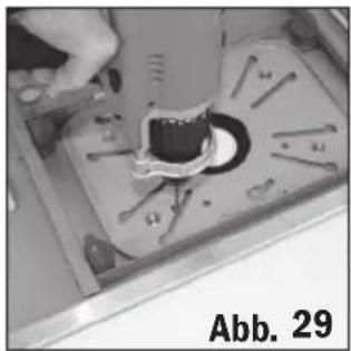
natural_image
Close-up of a mechanical component with a tool inserted, labeled 'Abb. 29' (no other text or symbols visible)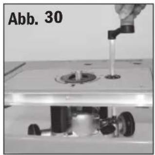
natural_image
Close-up of a mechanical assembly with a hand pouring liquid into a component (no visible text or symbols)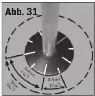
text_image
Abb. 31 0.4mm (√4.2) 2mm (√4.2) 0.2mm (√10.8)text_image
Exploded view diagram of a mechanical assembly with numbered parts and exploded view, likely for assembly or maintenance purposes.REF. NO. SKU DESCRIPTION
| 001 | TRA067 | SCREW MOTOR TOP COVER |
| 002 | TRA007 | MOTOR TOP COVER |
| 003 | TRA027 | SPEED CONTROLLER |
| 004 | TRC057 | POWER CORD |
| 005 | TRA068 COPPER RING B (BRUSH CONNECTION B) | |
| 006 | TRA069 | COPPER RING A (BRUSH CONNECTION A) |
| 007 | TRA018 | CORD GUARD |
| 008~010 | TRA136 | RACK POST GUIDE ASSEMBLY |
| 011 | TRA071 | SCREW UPPER ARMATURE BEALT |
| 012 | TRA016 | UPPER ARMATURE BEARING PLATE |
| 013 | TRA017 | CORD RESTRAIN |
| 014 | TRA072 | SCREW CORD RESTRAINT |
| 015~018, | TRA135 | SWITCH ASSEMBLY |
| 020 & 023 | ||
| 019 | TRA034 | DEPTH STOP SPRING GUIDE |
| 021 | TRA074 | SCREW CORD RESTRAIN |
| 022 | TRA075 | SCREW SWITCH COVER |
| 024 | TRA077 | BROWN CONNECT WIRE |
| 025 | TRA078 | BLUE CONNECT WIRE |
| 026 | TRA079 | SET SCREW |
| 027 | TRA056 | HOLDER BRUSH |
| 028 | TRA055 | BRUSH |
| 029 | TRA080 | CAP BRUSH |
| 030 | TRA081 | PAN HD SCREW |
| 031 | TRA035 | MICRO ADJUST KNOB |
| 032 | TRA005 | UPPER MOTOR BODY |
| 033 | TRA003 | FIELD COIL |
| 034 | TRA036-3 | WORM GEAR (START 2010) |
| 034.2 | TRA501 PIN | |
| 034.3 | TRA502 O-TYPE RING | |
| 034.4 | TRA503 FLAT WASHER | |
| 034.5 | TRA504 E RING | |
| 035 | TRA082 | SELF-TAP PAN HD SCREW/WASHER |
| 036~037 | TRA127 | MAGNET RING & MOUNT ASSEMBLY |
| 038 | TRA085 | BALL BEARING |
| 039 | TRA002 | ARMATURE ASSEMBLY |
| 040 | TRA024 | FAN SHROUD |
| 041 | TRA086 | SCREW LOWER ARMATURE BEALT |
| 042 | TRA015 | LOWER ARMATURE BEARING PLATE |
| 043 | TRA014 | BALL BEARING |
| 044 | TRA087 | E-RING (ETW) |
| 045 | TRA044 | PLUNGE HANDLE CLUTCH |
| 046 | TRA043 | PLUNGE HANDLE PINION |
| 047 | TRA037 | WORM WHEEL METRIC CW DOWN |
| 048 | TRA152 | SPRING PLUNGE HANDLE CLUTCH SHAFT |
| 049 | TRA150 | PLUNGE HANDLE CLUTCH SHAFT |
| 050 | TRA139 | PLUNGE HANDLE OUTER RUBBERISED(FOR PUSH BUTTON HANDLE) |
| 051 | TRA147 | PLUNGE HANDLE SHAFT |
| 051.1 | TRA141 PLUNGE SELECT PUSH BUTTON | |
| 051.2 | TRA142 PLUNGE SELECT BUTTON SPRING | |
| 051.3 | TRA143 SELF TAPPING SCREW | |
| 051.4 | TRA144 PLUNGE HANDLE ROTOR | |
| 051.5 | TRA145 PLUNGE HANDLE STATOR | |
| 051.6 | TRA146 PLUNGE HANDLE LOCKOUT | |
| 051.7 | TRA149 PIN | |
| 051.8 | TRA151 SPRING PLUNGE HANDLE ROTOR | |
| 052 | TRA140 | PLUNGE HANDLE INNER |
| 053 | TRA089 | SCREW CORD RESTRAINT |
| 054 | TRA090 | SPRING RELEASE RING |
| 055 | TRA148 | MICRO RELEASE RING |
REF. NO. SKU DESCRIPTION
| 057, 058 & 076 TRA052 LOWER MOTOR BODY & BUSH ASSEMBLY | |
| 059 TRA092 SPRING DEPTH STOP ROD | |
| 060 TRA033 DEPTH STOP ROD | |
| 061 TRA058 DEPTH STOP ROD PLUG | |
| 062 TRA046 FIXED HANDLE INNER(FOR PUSH BUTTON HANDLE) | |
| 063 TRA093 PAN HD SCREW | |
| 064 TRA045 FIXED HANDLE OUTER RUBBERISED(FOR PUSH BUTTON HANDLE) | |
| 065 TRA094 SELF TAPPING SCREW | |
| 066 TRA032 DEPTH STOP BRASS PLUG | |
| 067 TRA133 DEPTH SPRING | |
| 068~070 TRA134 DEPTH KNOB ASSEMBLY | |
| 071 TRA049 PLUNGE LOCK BOLT | |
| 072 TRA098 SCREW PLUNGE LOCK BOLT PLATE | |
| 073 TRA050 PLUNGE LOCK BOLT PLATE | |
| 074 TRA048 PLUNGE LOCK LEVER | |
| 075 TRA099 SCREW PLUNGE LOCK BOLT | |
| 077 TRA101 SELF-TAP PAN HD SCREW | |
| 078 TRA317A COLLET SHAFT | |
| 079 TRA104 INNER SPRING SHAFT LOCK | |
| 080 TRA026 SHAFT LOCK PIN | |
| 081 TRA105 SPRING SHAFT LOCK BUTTON | |
| 082 TRA025 SHAFT LOCK BUTTON | |
| 083 TRA106 SCREW SHAFT LOCK BUTTON | |
| 084 TRA107 PAN HD SCREW | |
| 085 TRA022 REAR CHIP SHIELD | |
| 086 TRA108 RACK POST LINER | |
| 087 TRA109 RETAIN RING | |
| 088 TRA110 SPRING RACK POST | |
| 091 TRA064 FENCE ATTACHMENT KONB | |
| 092 TRA111 SPRING FENCE ATTACHMENT KNOB | |
| 093 TRA021 FRONT CHIP SHIELD | |
| 094 TRA023 VACUUM SHIELD BIG THROAT | |
| 095 TRA030 TURRET WHEEL | |
| 096 TRA112 NUT, TURRET WHEEL | |
| 097 TRA028 TURRET | |
| 098 TRA113 SCREW, TURRET WHEEL | |
| 099 TRA114 SPRING FENCE ATTACHMENT KNOB | |
| 100 TRA029 TURRET DETENT BALL | |
| 089, 090, TRA125 BASE & POST ASSEMBLY | |
| 101, 103 | |
| 102 TRA115 SELF TAPPING SCREW | |
| 104 TRA009 BASE PLATE | |
| 105 TRA117 M6X40MM COACH BOLT | |
| 106 TRA118 SCREW | |
| 107~111 TRA128 FENCE PLATE & CIRCLE CUTTER ASSEMBLY | |
| 112~116 TRA126 FENCE ASSEMBLY | |
| 119 TRA066 WRENCH | |
| 120 WASHER | |
| 124~130 TRA410 COMPLETE WINDER HANDLE ASSEMBLY | |
| 131 12MM COLLET ASSEMBLY | |
| 132 8MM COLLET ASSEMBLY | |
| 133 WASHER | |
| 150 COPPER PAD | |
| 151 SCREW 1/4" X 7/8" FOR ROUTER TABLE |
CMT WARRANTY CMT warrants to the purchaser of this product that if any part proves to be defective due to faulty materials or workmanship within 1 YEAR from the date of original purchase, CMT will repair, or at its discretion replace, the faulty part free of charge.
This warranty does not apply to commercial use nor does it extend to normal wear and tear or damage as a result of accident, abuse or misuse.
If the product is faulty or requires service please refer to your nearest authorised CMT Repair Centre. Warranty does not include any freight to and from the user.
Date of Purchase: ____/____/____
Model: CMT7E
Serial Number: ____
(Located on motor label)
Retain your receipt as proof of purchase
Declaration of Conformity C€
We declare under our sole responsibility that the product described under “Technical Data” is in conformity with the following standards or standardization documents: EN 60745-1, EN 60745-2-17, EN 61000-4-4, EN 61000-4-5, 61000-6-3 according to the provisions of the directives 2011/65/UE, 2004/108/CE, 2006/42/CE, 2006/95/CE.
© C.M.T UTENSILI S.P.A.
®: CMT, the CMT logo and the orange color applied to tool surfaces are trademarks of C.M.T. UTENSILI S.P.A.
This document has been sent for your personal use only. All usage and reproduction is forbidden without written permission from C.M.T. UTENSILI S.P.A.
Any brand names mentioned in CMT product catalogues and on the CMT website are the property of their respective owners.
© C.M.T UTENSILI S.P.A.
CMT ORANGE TOOLS®
Watch the video on
YouTube