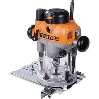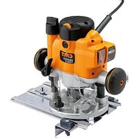
CMT8E - Milling machine CMT Orange Tools - Free user manual and instructions
Find the device manual for free CMT8E CMT Orange Tools in PDF.


User questions about CMT8E CMT Orange Tools
0 question about this device. Answer the ones you know or ask your own.
Ask a new question about this device
Download the instructions for your Milling machine in PDF format for free! Find your manual CMT8E - CMT Orange Tools and take your electronic device back in hand. On this page are published all the documents necessary for the use of your device. CMT8E by CMT Orange Tools.
USER MANUAL CMT8E CMT Orange Tools
natural_image
Black-and-white photo of a CMT tool in a workshop setting, no visible text or symbols on the device itself.CONTENTS
| Specifications | 2 |
| Features | 3 |
| Safety | 4 |
| Symbols | 7 |
| Functions | 8 |
| Hand-held Operation | 10 |
| Table-mounted Operation | 1 |
| Maintenance | 12 |
| Troubleshooting | 13 |
| Warranty | 14 |
| Declaration of Conformity | 74 |
SPECIFICATIONS
TECHNICAL DATA
Model no: E8TMC
| Motor: | 1010W soft start |
| Input: | 220 - 240V 50/60Hz |
| Speed: | 8,000 - 20,000min-1Speed maintenance under load |
| Collet: | 12mm and 8mm auto-releasing |
| Depth adjustment: | 1. Micro winder2. Conventional “free” plunge3. Through-table winder |
| Bit changes: | Through-base, single spanner action.Auto shaft lock |
| Guide: | Extended baseplate with adjustable fence |
| Tool weight: | 3.8kg (8.4lb) |
| Insulation class: | Double insulated |
| Vibration emission value: | ah= 5.958m/s2 |
| Uncertainty: | k= 1.5m/s2 |
| Sound pressure level: | 85.5 dB(A) |
| Sound power level: | 96.5 dB(A) |
FEATURES
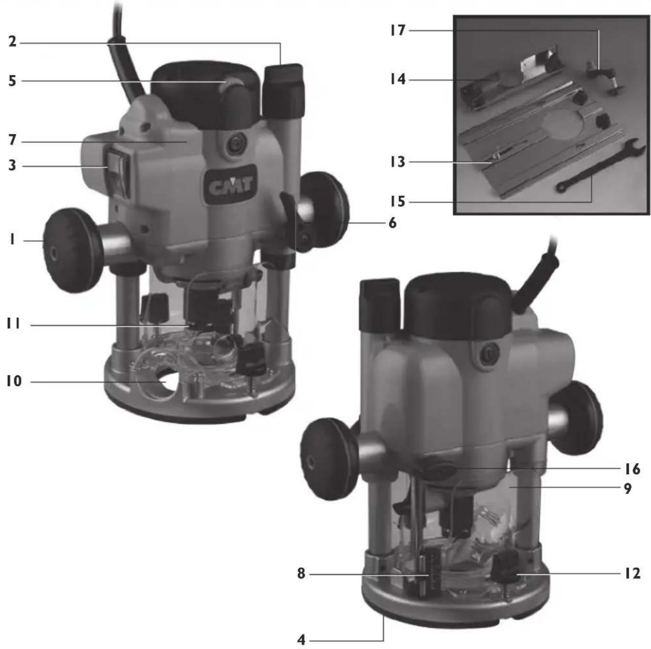
text_image
2 5 7 3 1 11 10 CMT 17 14 13 15 6 16 9 8 12 4I. Handles
2. Micro-winder
3. Illuminated power switch with lock-out cover
4. Table-winder connection point
5. Speed controller
6. Plunge lock lever
7. Motor
8. Depth gauge
9. Fully enclosed guarding
- Dust extraction port (suits 38mm (I 1/2") OD hoses)
II. 12mm auto-releasing collet - Mounting knobs
- Extended baseplate
- Fence
- Wrench
- Depth stop lock knob
- Table winder handle
GENERAL SAFETY RULES
Read and understand all instructions. Failure to follow all instructions listed below, may result in electric shock, fire and/or serious personal injury.
SAVE THESE INSTRUCTIONS
Work Area
- Keep your work area clean and well lit. Cluttered benches and dark areas invite accidents.
- Do not operate power tools in explosive atmospheres, such as in the presence of flammable liquids, gases or dust. Power tools create sparks which may ignite the dust or fumes.
- Keep bystanders, children, and visitors away while operating a power tool. Distractions can cause you to lose control.
Electrical Safety
- Double Insulated tools are equipped with a polarized plug (one blade is wider than the other). This plug will fit in a polarized outlet only one way. If the plug does not fit fully in the outlet, reverse the plug. If it still does not fit, contact a qualified electrician to install a polarized outlet. Do not change the plug in any way. Double Insulation☐ eliminates the need for the three wire grounded power cord and grounded power supply system.
- Avoid body contact with grounded surfaces such as pipes, radiators, ranges and refrigerators. There is an increased risk of electric shock if your body is grounded.
- Don't expose power tools to rain or wet conditions. Water entering a power tool will increase the risk of electric shock.
- Do not abuse the cord. Never use the cord for carrying the tool or pull the plug from an outlet. Keep cord away from heat, oil, sharp edges or moving parts. Replace damaged cords immediately. Damaged cords increase the risk of electric shock.
- When operating a power tool outside, use an outdoor extension cord marked "W-A" or "W". These cords are rated for outdoor use and reduce the risk of electric shock.
PERSONAL SAFETY
- Staalert, watch what you are doing, and use common sense when operating a power tool. Do not use tool while tired or under the influence of drugs, alcohol, or medication. A moment of inattention while operating power tools may result in serious personal injury.
- Dress properly. Do not wear loose clothing or jewelry. Contain long hair. Keep your hair, clothing, and gloves away from moving parts. Loose clothes, jewelry, or long hair can be caught in moving parts.
- Avoid accidental starting. Be sure switch is off before plugging in. Carrying tools with your finger on the switch or plugging in tools that have the switch on invites accidents.
- Do not overreach. Keep proper footing and balance at all times. Proper footing and balance enables better control of the tool in unexpected situations.
- Use safety equipment. Always wear eye protection. Dust mask, non-skid safety shoes, hard hat, or hearing protection must be used for appropriate conditions.
TOOL USE AND CARE
- Use clamps or other practical wato secure and support the workpiece to a stable platform. Holding the work by hand or against your body is unstable and may lead to loss of control.
-
Do not force the tool. Use the correct tool for your application. The correct tool will do the job better and safer at the rate for which it is designed.
-
Do not use the tool if switch does not turn it on or off. Any tool that cannot be controlled with the switch is dangerous and must be repaired.
- Disconnect the plug from the power source before making any adjustments, changing accessories, or storing the tool. Such preventative measures reduce the risk of accidental starting.
- Store idle tool out of reach of children and other untrained persons. Tools are dangerous in the hands of untrained users.
- Maintain tools with care. Keep cutting tools sharp and clean. Properly maintained tools, with sharp cutting edges are less likely to bind and are easier to control.
- Check for misalignment or binding of moving parts, and any other condition that may affect the tools operation. If damaged have the tool serviced before using. Many accidents are caused by poorly maintained tools.
- Use only accessories that are recommended by the manufacturer for your model. Accessories that may be suitable for one tool, may become hazardous when used on another tool.
SERVICE
- dol service must be performed only by qualified repair personnel. Service or maintenance performed by unqualified personnel could result in a risk of injury.
- When servicing a tool, use only identical replacement parts. Follow instructions in the Maintenance section of this manual. Use of unauthorized parts or failure to follow Maintenance Instructions may create a risk of electric shock or injury.
ADDITIONAL SAFETY RULES FOR ELECTRIC ROUTERS
- Hold tool:insulated gripping surfaces when performing an operation where the cutting tool may contact hidden wiring or its own cord. Contact with a “live” wire will make exposed metal parts of the tool “live” and shock the operator.
- Remove the plug from the socket before carrying out any adjustment, servicing or maintenance.
- Fully unwind cable drum extensions to avoid potential overheating.
- When an extension cable is required, you must ensure it has the right ampere rating for your power tool and is in a safe electrical condition.
- Ensure your mains supply voltage is the same as your tool rating plate voltage.
- Your tool is double insulated for additional protection against a possible electrical insulation failure within the tool.
• Always check walls, floors and ceilings to avoid hidden power cables and pipes.
• After long working periods external metal parts and accessories could be hot.
• Always wear eye and ear protection and use a dust mask. - Handle router bits with care, they can be extremely sharp.
- Check the bit carefully for signs of damage or cracks before use. Replace cracked or damaged bits immediately.
- Remove all nails, screws and other objects from the workpiece. You can damage the bit and the tool by cutting into a nail or other metal. It can also present a safety hazard.
• Always use both handles and make sure that you have a good grip on the router before proceeding with any work.
- Keep your hands away from the rotating bit.
• Make sure that the bit is not in contact with the workpiece when you switch the machine on. • Before using the tool to make a cut, switch on and let it run for a while. Watch for vibration or wobbling that could indicate an improperly installed bit.
• Take notice of the direction of rotation of the bit and the direction of feed.
- Do not leave the machine running unattended. Operate the tool only when controlled by both hands.
- Always switch off and wait until the bit has come to a complete standstill before removing the machine from the workpiece.
- Do not touch the bit immediately after operation. It may be extremely hot and could burn your skin.
- Rags, cloths, cord, string and the like should never be left around the work area.
- Use safety equipment including safety goggles or shield, ear protection, dust mask and protective clothing including safety gloves.
Before connecting a tool to a power source (power point receptacle, outlet, etc.) be sure that the voltage supply is the same as that specified on the nameplate of the tool. A power source with a voltage greater than that specified for the tool can result in serious injury to the user, as well as damage to the tool. If in doubt, do not plug in the tool. Using a power source with a voltage less than the nameplate rating is harmful to the motor.
The tool must be used only for its prescribed purpose. Any use other than those mentioned in this Manual will be considered a case of misuse. The user and not the manufacturer shall be liable for any damage or injury resulting from such cases of misuse.
The manufacturer shall not be liable for any changes made to the tool nor for any damage resulting from such changes.
Even when the tool is used as prescribed it is not possible to eliminate all residual risk factors. The following hazards may arise in connection with the tool's construction and design:
- Damage to hearing if effective earmuffs are not worn.
- Harmful emissions of wood dust when the machine is used in closed rooms. Always use supplementary dust extraction.
• Always remove the plug from the mains socket before making any adjustments or maintenance, including changing the bit. - Contact with the bit.
- Reaching into the housing whilst the tool is running and making contact with the bit.
- Kickback of workpiece and parts of workpiece.
- Bit fracture.
- Catapulting of faulty pieces from the bit.
- Do not use bits that are deformed or cracked.
SYMBOLS
ENVIRONMENTAL PROTECTION
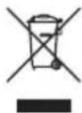
Waste electrical products should not be disposed of with household waste. Please recycle where facilities exist. Check with your local authority or retailer for recycling advice.

Always wear ear, eye and respiratory protection.

Double insulated.

Instruction warning.

Instruction note.

Conforms to relevant legislation and safety standards.
FUNCTIONS
POWER SWITCH
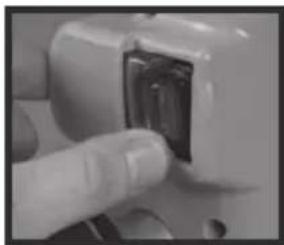
When the router is connected to power the switch (3) will illuminate (in both “on” and “off” positions).
The retracting switch shutter prevents accidental starting of the router. It must be retracted before the router can be switched on. The cover will remain open until the router is switched off.
natural_image
Close-up of a hand holding a small electronic component (no visible text or symbols)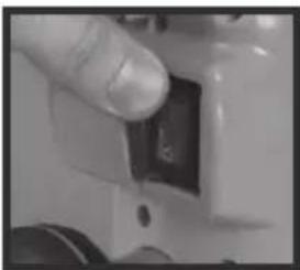
natural_image
Close-up of a finger pressing a small black button on a white surface (no visible text or symbols)CUT DEPTH ADJUSTMENT
There are two methods of cut depth adjustment, depending on the accuracy and control required: Free Plunge, for conventional & fast depth adjustment; and Micro Adjuster, for precise depth setting throughout the full plunge range.
Free Plunge
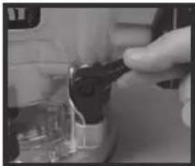
Release the Plunge Lock Lever (6). Push the body of the router until the desired depth is reached. Re-lock the plunge lock lever.
natural_image
Close-up of a hand holding a small object, possibly a tool or device, with no visible text or symbols.The position of the plunge lock lever can be altered by removing its retaining screw and repositioning the lever on the bolt. Re-tighten firmly.
Micro adjuster
I. Ensure that the plunge lock lever (6) is unlocked.

If the
micro winder (2)
the plunge lock lever engaged the micro winder will start clicking and the cut depth will remain unchanged.
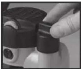
- Turn the Micro Winder Adjuster Knob (2) clockwise to increase cut depth and anti-clockwise to reduce cut depth.
natural_image
Close-up of a hand holding a black mechanical device with a white handle (no visible text or symbols)When the end of the depth adjustment range is reached the micro winder will offer greater resistance
to turn and will begin to "click".
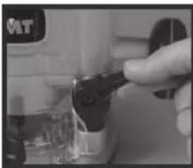
- Lock the plunge lever, particularly for heavy cuts.
natural_image
Close-up of a hand using a tool to press or install electronic components (no visible text or symbols)COLLET LOCK
-
Turn the power switch "off", allowing the retracting switch shutter to close. (The retracting shutter will lock closed when the collet lock is engaged.)
-
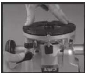
Place the router upside down, or on its side. With the motor completely stopped plunge the router to its maximum depth using the free plunge or winder handle plung
natural_image
Close-up of gloved hands operating a microscope instrument (no visible text or symbols)Ensure the depth stop (16) is fully retracted (see "Depth Stop and Turret"). The collet should be protruding through the base, allowing easy spanner access.
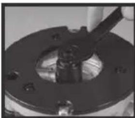
- Insert your router bit fully into the collet then use the spanner (15) to turn the collet slightly, allowing the collet lock to engage. Once
natural_image
Close-up of a mechanical component with a black flange and bolted base (no visible text or symbols)tuengagwithturn the spanner clockwise to tighten the cutter.
- Return the router to a normal operating depth. This will disengage the collet lock and release the retracting switch shutter, enabling access to the power switch.
REDUCING COLLET
A second collet (11) is supplied for the use of small shanked (eg. 8mm) cutters.
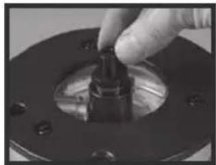
With the router in the collet lock position (see "Collet Lock" above) use the wrench to unscrew the standard collet, anti-clockwise, and remove it from the router. Tighten the reduced collet in its' place.
natural_image
Close-up of a hand adjusting a mechanical component with a circular base and bolt holes (no visible text or symbols)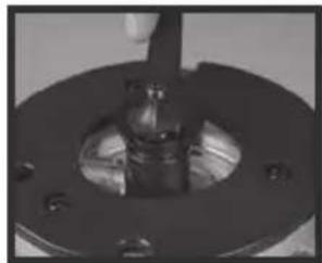
natural_image
Close-up of a mechanical component with a central shaft and flange (no visible text or symbols)VARIABLE SPEED CONTROL
Router speed settings are not critical
- generally the highest speed which does not result in burn marks on the workpiece should be used. Where stated, always follow the cutter manufacturers' maximum speed limitations.
Operating at reduced speed increases the risk of damage to the router as a result of overload. Use very slow feed rates and/or multiple shallow cuts.
The Speed Controller (5) is marked 1 to 5, corresponding approximately with the speeds and cutter diameters below. Turn the dial to select the desired speed.
natural_image
Close-up of a finger pressing a small white substance on a dark, textured surface (no visible text or symbols)Setting RPM Cutter Diameter
| 5 | 20,000 | Up to 25mm (1") | ||
| 4 | 17,000 | 25 - 50mm (1" - 2") | ||
| 3 | 13,500 | 50 - 52.5 | (2" - 2 | ^1/_16 ") |
| 2 | 10,000 | Over | 52.5mni"(2 | |
| 1 | 8,000 | Use only if burning | ||
DUST EXTRACTION
Dust Port
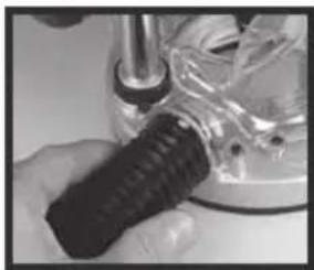
The CMT Router is equipped with a Dust Port (10) for chip extraction above the cut. It accepts 38mm (1½") O.D. hose, supplied with the CMT Dust Collector.
natural_image
Close-up of hands using a tool to adjust a mechanical component (no visible text or symbols)The hose screws into position via a left hand thread (anti-clockwise).
DEPTH STOP & TURRET
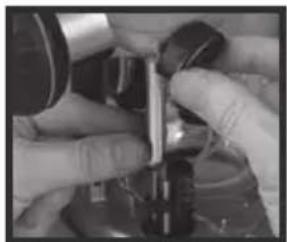
The Depth Stop (16) and Turret are used in the free plunge mode to accurately preset up to three different cut depths.
-
Loosen the Depth Stop Lock knob (16) and retract the depth stop fully, then re-tighten.
-
Set the Turret Thumbwheel(s) to the desired plunge depth(s) using the scales on the turret post.
-
Fit the cutter, and adjust the plunge depth until the cutter tip is level with your "zero datum" (eg. router base or Router Table surface).
-
Rotate the turret until the fixed turret post is in line with the depth stop. Release the stop, allowing it to spring onto the post, then re-tighten.
natural_image
Close-up of hands operating a mechanical device with a metallic lever (no visible text or symbols)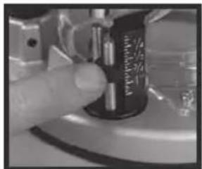
natural_image
Close-up of a finger pressing a black cylindrical component with a metallic handle (no visible text or symbols)
natural_image
Close-up of a hand holding a black plastic bottle with a lid (no visible text or symbols)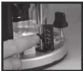
natural_image
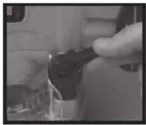
Close-up of a hand pressing a small black object on a metallic stand (no visible text or symbols)- Rotate the turret again until the bolt of the chosen thumbwheel is in line with the
stop. Plunge until the hollow depth stop locates over the bolt and hits the thumbwheel. Engage the plunge lock lever (6).
natural_image
Close-up of a hand holding a black tool near a small electronic component (no visible text or symbols)
The fixed turret stop can be used as a third predetermined depth stop.
This is achieved by setting all three stops by sight, rather than using the turret scale.
HAND-HELD OPERATION
• Always use both hands to control the router and ensure your workpiece is securely clamped to prevent any movement during operation.
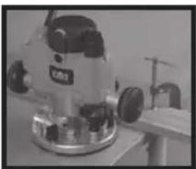
- Never operate the router free-hand without some form of guidance. Guidance can be provided by a bearing guided cutter, the fence guide
natural_image
Close-up of a precision machine with visible gears and mounting base (no text or symbols)supplied or a straight edge (eg. a batten clamped to your work as shown above).
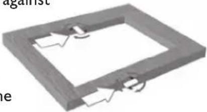
• Always feed against
the direction of cutter rotation (clockwise, as indicated by the arrows on the router base).
natural_image
3D diagram of a rectangular frame with internal arrows indicating movement or force, no text or symbols present- Do not operate the router upside down unless securely mounted in a well guarded router table (eg. CMT brand)
THE BASE ASSEMBLY
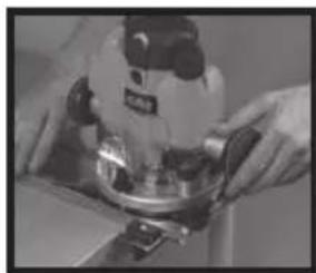
The Extended Baseplate (13) supplied with the CMT Router provides greater stability when using bearing guided cutters along an edge.
Place one hand on the long end of the base, holding it down onto your work, and grip the router handle, furthest away, with your other hand.
natural_image
Person using a power tool on a metal platform (no visible text or symbols)EXTENDED BASEPLATE AND FENCE
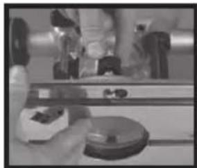
- To fit the extended baseplate (13) loosen the mounting knobs (12) approximately 10mm (3/8") up the coach bolt.
- Position the extended baseplate onto the base of the router with the heads of the coach bolts beneath the keyhole slots in the baseplate.

The router can be
mounted with the long overhang to the left or to the right depending on where the support is
natural_image
Person using a handheld device on a surface with blurred background objects (no visible text or symbols)required. For edge work, locate the power switch on the short overhang side of the base.
-
Push the mounting knobs (12) until the bolt heads locate into the keyholes, then slide the extended baseplate until the bolts locate against the ends of the keyhole slots. Tighten the knobs firmly.
-
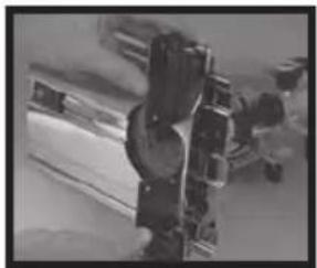
To fit the fence (14) loosen the fence knobs a few turns and slide the fence along the tracks on the base. Lock at the desired setting by tightening both fence
natural_image
Close-up of mechanical components or parts in a workshop setting (no visible text or symbols)When routing trenches some distance in from an edge, fit the fence to the long end of the base.
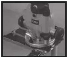
When performing edge work with a non-bearing guided cutter fit the fence to the short end of the base.
natural_image
Close-up of a precision optical instrument with metallic components and a mounted base (no visible text or symbols)If using a very large diameter cutter it may be necessary to fix wooden blocks to the fence faces via the screw holes, to ensure the cutter does not contact the fence.
Circle Cutting
I. Fit the extended base (without fence) to the router.
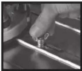
- Remove the pivot mount from the base and fix it to the centre of your work using a small nail or screw through one of the holes in the pivot mount. Leave the pivot in position.

natural_image
Close-up of a hand using a tool to apply a small metallic component onto a dark surface (no visible text or symbols)- Lower the router and base over the pivot mount and refit the washer and wing-nut.
natural_image
Close-up of a hand holding a small metallic tool, partially visible against a dark surface (no text or symbols)-
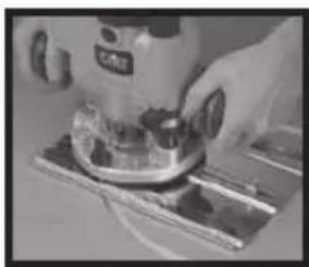
With the power switched "Off", rotate the router along the intended path to check make any necessary ad
-
Cut the circle in several passes, lowering the cut depth by say 2mm (1/16") each pass. Do not attempt to cut deeply in one pass.
natural_image
Close-up of hands using a power tool on a workbench (no visible text or symbols)Through cuts: If cutting all the way through the material, fix a sacrificial board to the underneath of your workpiece. Cut the circle oversize, then when the cut is all the way through, reduce the diameter and work back to the desired size, using light, full depth passes.
- Fitting and operating this router on a Router Table should be done in accordance to the literature supplied with your Router Table.
- While this product was designed for efficient and convenient operation on most router tables, it is particularly suited to CMT brand tables.
- Router adjustments are made extremely easy using the unique features described earlier in the manual. Refer to “Fitting & Changing Cutters” and “Cut Depth Adjustment”.
TABLE WINDER ACCESSORY
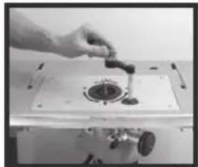
I. Mount the router securely into your router table as detailed in your router table instructions. Turn the table (with router fitted) upside down.
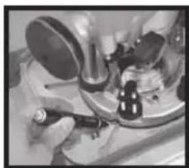
- With a marker pen trace the scallop in the base of the router onto the underneath of your router table. Complete the tracing to form a circle approximately 12mm (
natural_image
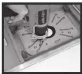
Close-up of hands using a tool on a workbench with mechanical components (no visible text or symbols)- Remove the router and drill a pilot hole through the centre of your circle. Using a 12mm (1/2") bit drill your final access hole.
natural_image
Close-up of a hand holding a small object with a black cap and multiple pins, placed on a metal tray (no visible text or symbols)
File off any rough burrs using a
round file.
natural_image
Close-up of a hand using a tool to apply material onto a mechanical component (no visible text or symbols)-
Refit the router and turn the router table right way up.
-
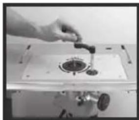
Fit the table winder handle (17) through the hole in the tabletop and push it onto the routers winder mechanism.

If necessary extend your hole using a round file.
- Release the plunge lock lever and use the winder handle to set your cut depth.
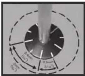
Calibration marks: Each line on the winder wheel represents 0.2mm (1/128") cut depth increments. A full 360 degree turn is equal to a 2mm (3/32") depth adjustment.
text_image
80° 65° 45° 15°- Re-lock the plunge lock lever and commence your work.
MAINTENANCE
- Any damage to the router should be repaired and carefully inspected before use, by qualified repair personnel. Service or maintenance performed by unqualified personnel could result in a risk of injury.
- Servicing should only be carried out by authorised CMT Repair Centres using original CMT replacement parts. Follow instructions carefully and refer to “Trouble-shooting” for problem identification and advice. Use of unauthorised or faulty parts may create a risk of electric shock or injury.
- CMT Manufacturing & Design Co. will not be responsible for any damage or injury caused by unauthorised repair of the router or by mishandling of the tool.
BRUSH REPLACEMENT
The carbon brushes are a consumable item which should be inspected periodically and replaced when worn. Failure to do so may result in damage to the motor.
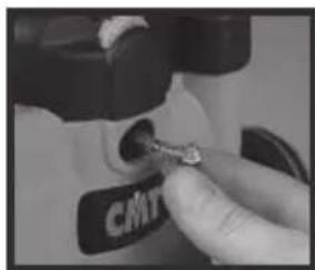
I. With the router disconnected from power, unscrew the Brush Caps located on the front and rear of the motor.
2. Remove the brushes by pulling carefully on the protruding springs.
3. If either of the brushes is worn to less than 6mm long, they must both be replaced using genuine CMT replacement brushes
- available from
Authorised CMT Repair Centres.
natural_image
Close-up of a hand inserting a small object into a device labeled 'CATY' (no additional text or symbols visible)POWER CORD REPLACEMENT
If the supply cord needs replacing, the task must be carried out by the manufacturer, the manufacturer's agent, or an authorised service centre in order to avoid a safety hazard.
TROUBLESHOOTING
This chart contains information to assist in resolving router problems.
If a problem cannot be resolved using this advice do not tamper with the router - contact your local CMT branch for referral to your nearest authorised repair centre.
SYMPTOM POSSIBLE CAUSE REMEDY
| Router will not operate • No supply of power • Check that power is available at source | ||
| Router runs slowly • Blunt or damage cutter • Re-sharpen or replace cutter | ||
| Makes an unusual sound • Mechanical obstruction • Contact Repair Centre | ||
| Excessive vibration | • Bent cutter shank | • Replace cutter |
| Heavy sparking occurs inside motor housing | • Brushes not moving freely | • Disconnect power, remove brushes, clean or replace |
| • Armature short circuited or open circuited | • Contact Repair Centre | |
| • Commutator dirty | • Contact Repair Centre | |
| Micro adjuster “clicks” | • Plunge lock engaged | • Release plunge lock lever |
| • Plunge selector button is released | • Engage the plunge selector button. Refer to “Handle Winder Plunge” | |
| • Reached end of adjustment range. | • Reset the router. | |
| Plunge lock lever not locking | • Plunge lock lever not correctly positioned | • Reposition plunge lock lever as described in “Free Plunge” |
| Shutter on power switch not releasing | • Router is plunged to full depth - in collet lock position | • Reduce plunge depth |
| Can’t plunge to collet lock position | • Power switch “On” | • Switch power “Off” |
WARRANTY
Model: CMT8E
Serial Number: ____
(Located on motor label)
Retain your receipt as proof of purchase
CMT warrants to the purchaser of this product that if any part proves to be defective due to faulty materials or workmanship within 1 YEAR from the date of original purchase, CMT will repair, or at its discretion replace, the faulty part free of charge.
This warranty does not apply to commercial use nor does it extend to normal wear and tear or damage as a result of accident, abuse or misuse.
If the product is faulty or requires service please refer to your nearest authorised CMT Repair Centre. Warranty does not include any freight to and from the user.
GB
SOMMAIRE
natural_image
Close-up of a finger pressing a small black object on a white electrical socket (no visible text or symbols)
natural_image
Close-up of a finger pressing a small black button on a white surface (no text or symbols visible)RÉGLAGE DE LA PROFONDEUR DE COUPE
natural_image
Close-up of a hand using a tool to adjust or install electronic components (no visible text or symbols)
natural_image
Close-up of a hand holding a black and white handheld device (no visible text or symbols)natural_image
Close-up of a hand using a tool to adjust or install a mechanical component (no visible text or symbols)CHANGEMENT DES FERS SERRAGE DU
natural_image
Close-up of hands operating a microscope with a black lens (no visible text or symbols)natural_image
Close-up of a mechanical component with a central shaft and flange (no visible text or symbols)natural_image
Close-up of a hand adjusting a mechanical component on a dark circular base (no visible text or symbols)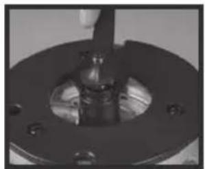
natural_image
Close-up of a mechanical component with a central shaft and mounting holes (no visible text or symbols)VITESSE VARIABLE
natural_image
Close-up of a finger pressing a small object on a dark surface (no visible text or symbols)natural_image
Close-up of hands using a screwdriver to adjust a mechanical component (no visible text or symbols)BOUTON DE VERROUILLAGE DE LA BUTEE DE PROFONDEUR ET TOURELLE A TROIS ETAGES
natural_image
Close-up of hands assembling or adjusting a mechanical component (no visible text or symbols)natural_image
Close-up of a finger pressing a black cylindrical component with visible internal structure (no text or symbols)natural_image
Close-up of a hand adjusting a black plastic component (no visible text or symbols)natural_image
Close-up of a hand pressing a small object on a metallic surface, with no visible text or symbols.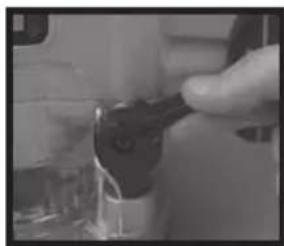
natural_image
Close-up of a hand holding a black mechanical component, possibly a tool or device (no visible text or symbols)natural_image
Close-up of a precision optical instrument with mounted components (no visible text or symbols)natural_image
3D diagram of a rectangular frame with internal arrows indicating rotation or movement (no text or symbols)natural_image
Close-up of hands operating a kitchen appliance with a large bowl (no visible text or symbols)natural_image
Person using a tool on a mechanical component, no visible text or symbolsnatural_image
Close-up of mechanical components or tools with no visible text or symbolsnatural_image
Close-up of a mechanical surveying instrument with no visible text or symbolsDécoupage de cercle
natural_image
Close-up of a hand using a hammer to press a small metallic object on a dark surface (no text or symbols visible)natural_image
Close-up of a hand holding a small metallic object, possibly a tool or component, with no visible text or symbols.natural_image
Person using a power tool on a circuit board (no visible text or symbols)natural_image
Close-up of hands operating a mechanical device with tools and components (no visible text or symbols)natural_image
Close-up of a mechanical component with tools and a central part (no visible text or symbols)
natural_image
Hand pouring liquid into a mechanical component (no visible text or symbols)
text_image
35° 0.2mm (0.1°)REPLACEMENT DES BROSSES
natural_image
Close-up of a hand inserting a small metallic object into a device labeled 'CMT' (no additional text or symbols visible)SYMPTÔME CAUSE POSSIBLE REMÈDE
natural_image
Close-up of a hand holding an open electrical socket (no visible text or symbols)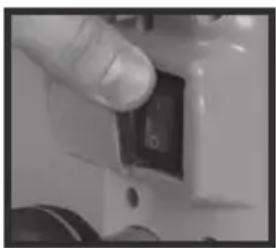
natural_image
Close-up of a finger pressing a small black component on a white surface (no visible text or symbols)natural_image
Close-up of a hand using a tool to adjust or install a mechanical component (no visible text or symbols)
natural_image
Close-up of a hand holding a small black and white device with a circular button (no visible text or symbols)
natural_image
Close-up of a hand inserting a small black object into a device (no visible text or symbols)EINSETZEN UND WECHSELN DER FRÄSER
natural_image
Close-up of hands operating a mechanical device with a black lid and control knob (no visible text or symbols)
natural_image
Close-up of a mechanical component with a central hole and flange (no visible text or symbols)
natural_image
Close-up of a hand holding a small mechanical component on a circular base (no visible text or symbols)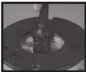
natural_image
Close-up of a mechanical component with a central shaft and flange (no visible text or symbols)DREHZAHLREGELUNG
natural_image
Close-up of a finger pointing to a small, dark, textured object (no visible text or symbols)natural_image
Close-up of a hand using a tool to adjust or install a mechanical component (no visible text or symbols)natural_image
Close-up of hands operating a mechanical device with a tool (no visible text or symbols)natural_image
Close-up of a hand holding a Coca-Cola beverage can with visible branding (no text or symbols on the can itself)natural_image
Close-up of a hand holding a black plastic bottle with a cap (no visible text or symbols)natural_image
Hand placing a dark object into a container with glass and a small lamp (no visible text or symbols)natural_image
Close-up of a hand holding a small black object, possibly a device or tool, with no visible text or symbols.natural_image
Close-up of a precision machine with no visible text or symbols on its bodynatural_image
Simple 3D diagram of a rectangular frame with internal cutouts and directional arrows, no text or symbols present.natural_image
Close-up of hands operating a mechanical device with a metallic component (no visible text or symbols)natural_image
Close-up of a hand holding a metal rod with a circular component, possibly part of a device or tool (no visible text or symbols)natural_image
Black and white photo of a robotic arm with visible joints and legs, set against a cloudy sky background (no text or symbols)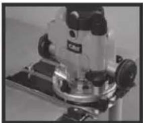
natural_image
Close-up of a precision optical instrument with metallic components and a base mount (no visible text or symbols)natural_image
Close-up of a hand using a tool to apply a small component onto a black base (no visible text or symbols)natural_image
Close-up of a hand using a tool to press or install a metal component on a surface (no visible text or symbols)natural_image
Close-up of a hand using a power tool on a workbench (no visible text or symbols)natural_image
Close-up of a mechanical device with a tool and clamped components (no visible text or symbols)natural_image
Close-up of a hand holding a small object with a label, placed on a surface with tools and a circular base (no readable text or symbols)
natural_image
Hand pouring liquid into a mechanical component (no visible text or symbols)text_image
4.2mm 0.6mmnatural_image
Close-up of a hand inserting a small metallic component into a device labeled 'CMT' (no additional text or symbols visible)natural_image
Close-up of a finger pressing a button on a white electrical socket (no visible text or symbols)
natural_image
Close-up of a finger pressing a small black button on a white surface (no visible text or symbols)natural_image
Close-up of a hand holding a black tool near a transparent container (no visible text or symbols)
natural_image
Close-up of a hand holding a small electronic device with a black handle and white base (no visible text or symbols)
natural_image
Close-up of a hand holding a small black object, possibly a tool or device, with no visible text or symbols.MONTARE E CAMBIARE LE FRESE
natural_image
Close-up of hands operating a mechanical device with a black lid and lever (no visible text or symbols)
natural_image
Close-up of a mechanical component with a central metallic part and mounting holes (no visible text or symbols)
natural_image
Close-up of a hand adjusting a mechanical component on a circular base (no visible text or symbols)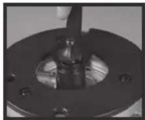
natural_image
Close-up of a mechanical component with a central shaft and flange (no visible text or symbols)CONTROLLO DI VELOCITÀ VARIABILE
natural_image
Close-up of a finger pressing a small object on a dark, textured surface (no visible text or symbols)natural_image
Close-up of hands using a screwdriver to adjust mechanical components (no visible text or symbols)BLOCCO PROFONDITÀ E TORRETTA
natural_image
Close-up of hands assembling or adjusting a mechanical component (no visible text or symbols)natural_image
Close-up of a hand using a sewing machine to press or adjust a black mechanical component (no visible text or symbols)natural_image
Close-up of a hand adjusting a black plastic bottle (no visible text or symbols)natural_image
Close-up of a hand holding a small object with a dark label, next to a glass container (no visible text or symbols)natural_image
Close-up of a hand holding a black plastic object, possibly a tool or device (no visible text or symbols)
natural_image
Close-up of a precision machine with control knobs and a base mount (no visible text or symbols)natural_image
3D rendering of a rectangular frame with internal cutouts and mounting brackets (no text or symbols)natural_image
Person operating a mechanical device with a circular component on a table (no visible text or symbols)natural_image
Close-up of mechanical components or parts in grayscale, no visible text or symbols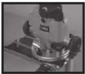
natural_image
Close-up of a precision optical instrument with metallic components and a mounted base (no visible text or symbols)UTILIZZO DELLA GUIDA DIRITTA
Base estesa
natural_image
Close-up of a hand using a tool to apply a small metallic component on a dark surface (no visible text or symbols)natural_image
Close-up of a hand holding a small metallic tool over a metal sheet, with no visible text or symbols.natural_image
Close-up of a lab bench with microscope and mechanical components (no visible text or symbols)natural_image
Close-up of a hand placing a small object into a container with arrows and a label (no readable text or symbols)
Togliere eventuali
natural_image
Close-up of a hand using a tool to press or inspect a circular component on a workbench (no visible text or symbols)natural_image
Close-up of a hand inserting a small metallic object into a mechanical component (no visible text or symbols)RICERCA GUASTI
natural_image
Close-up of a hand holding a small electronic component (no visible text or symbols)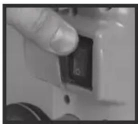
natural_image
Close-up of a finger pressing a small black button on a white mechanical component (no visible text or symbols)AJUSTE DE LA PROFUNDIDAD DE CORTE
natural_image
Close-up of a hand holding a small electronic device with a black connector (no visible text or symbols)
natural_image
Close-up of a hand holding a black and white handheld device with a circular button (no visible text or symbols)
natural_image
Close-up of a hand using a tool to adjust or install a mechanical component (no visible text or symbols)natural_image
Close-up of hands operating a mechanical device with a central knob (no visible text or symbols)
natural_image
Close-up of a mechanical component with a central hole and mounting holes (no visible text or symbols)natural_image
Close-up of a hand adjusting a black mechanical component on a circular base (no visible text or symbols)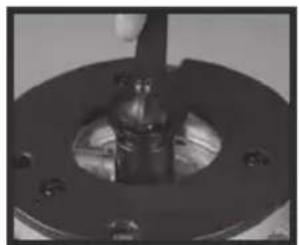
natural_image
Close-up of a mechanical component with a central shaft and flange (no visible text or symbols)CONTROL VARIABLE DE VELOCIDAD
natural_image
Close-up of a finger pressing a small object on a black surface (no visible text or symbols)natural_image
Close-up of a hand using a screwdriver to adjust a mechanical component (no visible text or symbols)TOPE DE PROFUNDIDAD Y TORRE
natural_image
Close-up of hands operating a mechanical device with a metallic component (no visible text or symbols)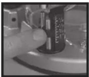
natural_image
Close-up of a finger pressing a button on a mechanical component (no visible text or symbols)
natural_image
Close-up of a hand holding a black cylindrical object with a white base, possibly a container or mechanical component (no visible text or symbols)natural_image
Close-up of a hand holding a small black object on a metallic stand (no visible text or symbols)natural_image
Close-up of a hand holding a small object, possibly a device or tool, with no visible text or symbols.
natural_image
Close-up of a precision machine with adjustable arms and a flat base (no visible text or symbols)natural_image
Close-up of hands operating a kitchen appliance with a large bowl (no visible text or symbols)natural_image
Close-up of a hand holding a metallic object with a circular base, possibly part of a lab or industrial equipment (no visible text or symbols)natural_image
Close-up of mechanical components or parts in grayscale, no visible text or symbolsnatural_image
Close-up of a microscope instrument with no visible text or symbolsUSO DE LA GUÍA
Base extendida
natural_image
Close-up of a hand using a hammer to apply a small metallic component on a dark surface (no visible text or symbols)natural_image
Close-up of a hand holding a small metallic object over a surface, with no visible text or symbols.natural_image
Close-up of hands using a mechanical tool on a workbench (no visible text or symbols)natural_image
Close-up of a hand holding a small object with a label, surrounded by mechanical parts (no readable text or symbols)
natural_image
Hand using a tool to adjust or install a mechanical component (no visible text or symbols)text_image
30° 5° 0.3mm (1/4×)natural_image
Close-up of a hand inserting a key into a CMT device (no text or symbols visible)text_image
Exploded view diagram of a mechanical assembly with numbered parts and exploded views for assembly or maintenance.SPARE LISTING
| NO. | DESCRIPTION | QTY | |
| 1 | SCREW, MOTOR TOP COVER 2 | ||
| 2 | MOTOR TOP COVER 1 | ||
| 3 | A681026201R | SPEED | CONTROLLER |
| 4 | SET SCREW 2 | ||
| 5 | PAN HD SCREW 1 | ||
| 6 | MICRO ADJUST KNOB 1 | ||
| 7 | UPPER MOTOR BODY | 1 | |
| 8 | A681030402R | FIELD | |
| 9 | PAN HD SELF-TAP SCREW/WASHER | 2 | |
| 10 | FAN SHROUD | 1 | |
| 11 | MAGNET RING AND MOUNT ASS'Y | 1 | |
| 12 | BALL BEARING | 1 | |
| 13 | A681030302R | ARMATURE | 1 |
| 14 | BALL BEARING | 1 | |
| 15 | SPRING DEPTH STOP ROD | 1 | |
| 16 | TUBE, DEPTH STOP ASS'Y | 1 | |
| 16.1 | TUBE, DEPTH STOP 1 | ||
| 16.2 | DEPTH STOP ROD PLUG | 1 | |
| 17 | FLAT WASHER | 2 | |
| 18 | HEX SOC HD SCREW | 1 | |
| 19 | KNOB DEPTH STOP | 1 | |
| 20 | SPECIAL SCREW | 2 | |
| 21 | COPPER PAD | 2 | |
| 22 | FIXED HANDLE INER | 2 | |
| 23 | PAN HD SCREW 4 | ||
| 24 | FIXED HANDLE OUTER | 2 | |
| 25 | SCREW | 2 | |
| 26 | SHAFT LOCK BUTTON 1 | ||
| 27 | PAN HD SCREW 1 | ||
| 28 | NOSE SHAFT LOCK | 1 | |
| 29 | SPRING SHAFT LOCK BUTTON | 1 | |
| 30 | SHAFT LOCK PIN | 1 | |
| 31 | INNER SPRING,SHAFT LOCK 1 | ||
| 32 | POST DUST SEAL STRIP | 2 | |
| 33 | POST DUST SEAL CAP 2 | ||
| 37 | A681020905R | 1/2" CHUCK ASS'Y | 1 |
| 38 | A681020904R | 1/4" CHUCK ASS'Y | 1 |
| 39 | SELF-TAP PAN HD SCREW | 4 | |
| 40 | SCREW PLUNGE LOCK BOLT | 1 | |
| 41 | PLUNGE LOCK LEVER | 1 | |
| 42 | SPRING PLUNGE LOCK LEVER | 1 | |
| 43 | LOWER MOTOR BODY | 1 | |
| 44 | CROSS RECESSED TRUSS HEAD SCREW | 2 | |
| 45 | BRUSH HOLDER 2 | ||
| 46 | BRUSH | 2 | |
| 47 | BRUSH HOLDER CAP 2 | ||
| 48 | SCREW SWITCH MOUNT | 2 | |
| 49 | HOUSING COVER SWITCH END | 1 | |
| 50 | SPRING SWITCH COVER | 1 | |
| 51 | SWITCH | 1 | |
| 52 | SWITCH SLIDE COVER | 1 | |
| 53 | SWITCH COVER | 1 | |
| 54 | SELF TAPPING SCREW | 4 | |
| 55 | 0681030213R-37CMT NAMEPLATE | 1 | |
| 56 | 0681020705R POWER CORD | 1 | |
| 57 | CORD CLAMP | 1 | |
| 58 | SELF TAPPING SCREW | 2 | |
| 59 | 9681035713103R RATING LABEL | 1 | |
| 60 | RETAIN RING | 1 | |
| 61 | ELEVATION THREAD ROD | 1 | |
| 61.1 | ELEVATION THREAD ROD | 1 | |
| 61.2 | ROUND NUT | 1 | |
| 61.3 | WASHER | 1 | |
| 61.4 | ELEVATION SHAFT 1 | ||
| 64 | MAIN SPRING | 1 | |
| 65 | FLAT WASHER | 3 | |
| 66 | GUIDETUBE | 1 | |
| 67 | PIN | 2 | |
| 68 | INT'RETAINING RING | 2 | |
| 69 | DRIVE HEAD | 1 | |
| 70 | O-TYPE RING | 1 | |
| 71 | A681016403R | TURRET ASS'Y | 1 |
| 71.1 | TURRETWHEEL | 2 | |
| 71.2 | HEX NUT | 2 | |
| 71.3 | TURRET | 1 | |
| 71.4 | SCREWTURRET | 2 | |
| 77 | SPRING FENCE ATTACHMENT KNOB | 1 | |
| 78 | TURRET DETENT BALL | 1 | |
| 79 | SET SCREW 2 | ||
| 80 | SCREW (SELF-TAPPING, CLAMP) | 1 | |
| 81 | PAN HD SCREW 3 | ||
| 82 | BASE PLATE | 1 | |
| 83 | M6X40MM COACH BOLT | 2 | |
| 84 | BASE | 1 | |
| 85 | SPRING FENCE ATTACHMENT KNOB | 2 | |
| 86 | FENCE ATTACHMENT KONB | 2 | |
| 87 | SMOOTH POST | 1 | |
| 88 | RACK POST | 1 | |
| 89 | SNAP RING RACK POST 20MM | 1 | |
| 90 | FRONT CHIP SHIELD 1 | ||
| 91 | PAN HD SCREW 5 | ||
| 92 | REAR CHIP SHIELD | 1 | |
| 93 | WRENCH | 1 | |
| 9681035710903R | COLOR BOX | ||
| 9681035710503R | MANUAL | ||
| PLASTIC BAG | 1 | ||
| PLASTIC BAG | 1 | ||
| POLYLON | 1 | ||
| PE FILM | 1 | ||
| 101 | 0681010241R | FENCE SLIDE KONB | 2 |
| 102 | 412012043R | WASHER FENCE CIRCLE | 2 |
| 103 | 410192012R | SELF-TAP PAN HD SCREW | 2 |
| 104 | 0681010304R | FENCE SLIDE FACE 1 | |
| 105 | 0681010303R | FENCE PLATE | 2 |
| 106 | 0681020217R | FENCE ADAPTOR | 2 |
| 107 | 411172001R | BUTTERFLY NUT | 1 |
| 108 | 412012043R | WASHER FENCE CIRCLE | 1 |
| 109 | 410012010R | HEX HD SCREW | 2 |
| 110 | 0681010240R | FENCE SLIDE CLAMP | 2 |
| 111 | 0681010242R | FENCE CIRCLE SLIDER 1 | |
| 112 | 0681010801R | SCREW FENCE CIRCLES LIDER | 1 |
| 300 | A681034401R | MICRO HEIGHT CRANK ARM | 1 |
| 300.1 | 0681020226R | MICRO HEIGHT ADJUSTERKNOB | 1 |
| 300.2 | 0681020227R | MICRO HEIGHT CRANK ARM | 1 |
| 300.3 | 41201A108R | FLAT WASHER | 1 |
| 300.4 | 41056A013R | SELF TAPPING SCREW | 1 |
| 300.5 | 0681031801R | MICRO HEIGHT DRIVE TUBE | 1 |
| 300.6 | 0681020233R | MICRO HEIGHT POSITION INDICATOR | 1 |
| 300.7 | 0681020501R | MICRO HEIGHT UNIVERSAL | 1 |
CMT ORANGE TOOLS™
www.cmtutensili.com CMT UTENSILI S.p.A. - PESARO - ITALY
DECLARATION OF CONFORMITY Low Voltage Directive: 2006/95/EC (amended by 73/23/EEC, Machinery Directive: 2006/42/EC (amended by 98/37/EC), EMC Directive: 2004/108/EC (amended by 89/336/EEC))
Product Description: Plunge Router 1010 W Ref.No.: CMT8E, CMT Brand, CMT Utensili S.p.A.
We, (CMT Utensili S.p.A.), declare that the above designated product is in conformity with the LVD, Machinery and EMC Directives and compliance is shown by testing and certification to the following standards;
On Behalf of CMT S.p.A.

Name: Mr. Marcello Tommassini
Position: CEO
© C.M.T UTENSILI S.P.A.
®: CMT, the CMT logo and the orange color applied to tool surfaces are trademarks of C.M.T. UTENSILI S.P.A.
This document has been sent for your personal use only. All usage and reproduction
is forbidden without written permission from C.M.T. UTENSILI S.P.A.
Any brand names mentioned in CMT product catalogues and on the CMT website are the property of their respective owners.
© C.M.T UTENSILI S.P.A.
CMT ORANGE TOOLS®