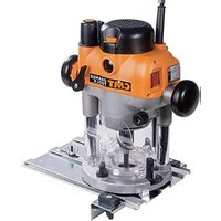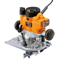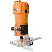
CMT10 - Milling machine CMT Orange Tools - Free user manual and instructions
Find the device manual for free CMT10 CMT Orange Tools in PDF.


User questions about CMT10 CMT Orange Tools
0 question about this device. Answer the ones you know or ask your own.
Ask a new question about this device
Download the instructions for your Milling machine in PDF format for free! Find your manual CMT10 - CMT Orange Tools and take your electronic device back in hand. On this page are published all the documents necessary for the use of your device. CMT10 by CMT Orange Tools.
USER MANUAL CMT10 CMT Orange Tools
natural_image
Exterior view of a CMT orange tools (no text or symbols visible on the device itself)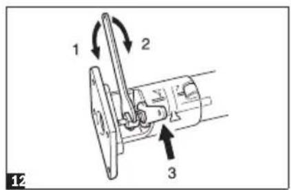
text_image
1 2 3 12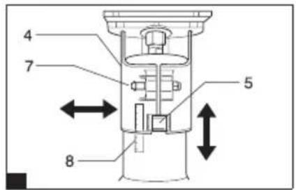
text_image
4 7 5 8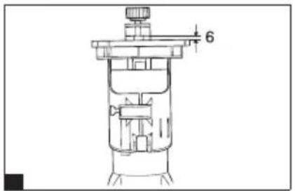
text_image
6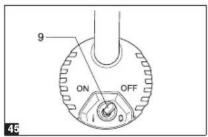
text_image
9 ON OFF 0 45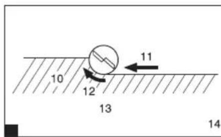
text_image
10 12 13 11 14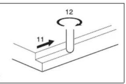
text_image
12 11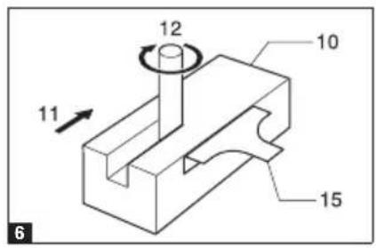
text_image
12 10 11 15 6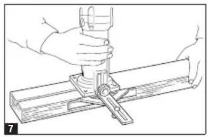
natural_image
Line drawing of hands using a tool to adjust or install a mechanical component (no text or symbols present)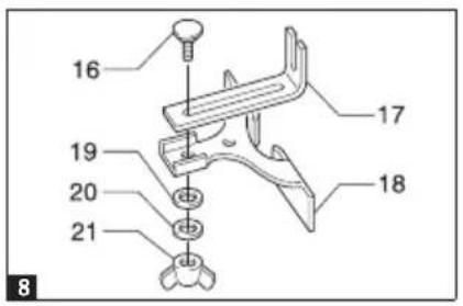
text_image
16 17 18 19 20 21 8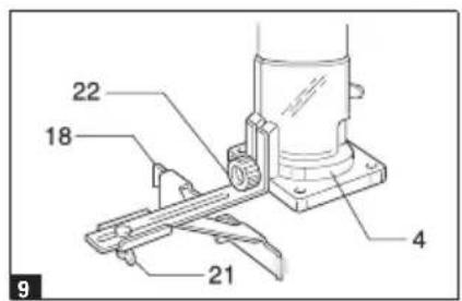
text_image
22 18 4 21 9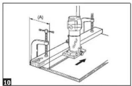
text_image
(A) 10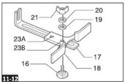
text_image
21 20 19 23A 23B 16 17 18 11-12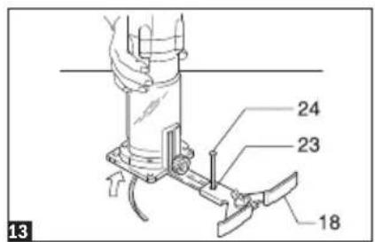
text_image
13 24 23 18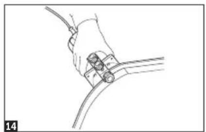
natural_image
Line drawing of a hand holding a cable with a connector, no text or symbols present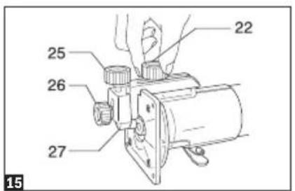
text_image
22 25 26 27 15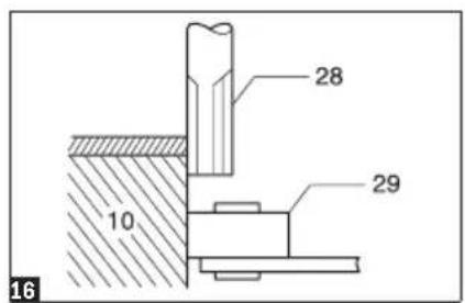
text_image
28 10 29 16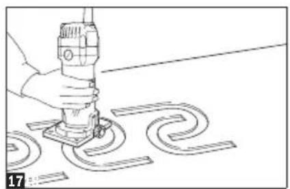
natural_image
Line drawing of a hand using a power tool to cut or mark a patterned surface (no text or symbols)
text_image
30 31 32 32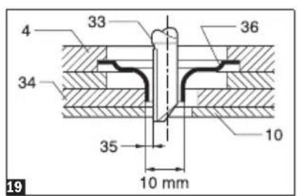
text_image
4 33 36 34 10 35 10 mm 19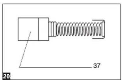
text_image
20 37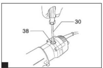
text_image
30 38Explanation of general view
| 1 Loosen | 15 Trimmer shoe, straight guide or trimmer guide | 27 Trimmer guide |
| 2 Tighten | 28 Bit | |
| 3 Hold | 16 Bolt | 29 Guide roller |
| 4 Base | 17 Guide plate | 30 Screwdriver |
| 5 Adjusting roller | 18 Straight guide | 31 Base protector |
| 6 Bit protrusion | 19 Flat washer | 32 Screws |
| 7 Lever | 20 Wave washer | 33 Straight bit |
| 8 Scale | 21 Wing nut | 34 Templet |
| 9 Switch lever | 22 Clamp screw (A) | 35 Distance (X) |
| 10 Workpiece | 23A Centre hole (70-121mm) | 36 Templet guide 10 |
| 11 Feed direction | 23B Centre hole (122-221mm) | 37 Limit mark |
| 12 Bit revolving direction | 24 Nail | 38 Brush holder cap |
| 13 View from the top of the tool | 25 Adjusting screw | |
| 14 Correct bit feed direction | 26 Clamp screw (B) |
| CMT10 | ||
| Power input W 550 | ||
| No load speed min | -1 | 32.000 |
| Collet mm 6-6.35-8 | ||
| Routing depth | mm | 0-40 |
| Tool weight | Kg | 1.6 |
These data are valid for nominal voltages of [U] 220\~230 V \~ 50/60 Hz. These values may change of the voltage was lower and in the specific embodiments for certain countries.
- Due to the continuing program of research and development, the specifications herein are subject to change without prior notice.
• Note: Specifications may differ from country to country.
1. Intended use
The tool is intended for flush trimming and profiling of wood, plastic and similar materials.
2. Power supply
The tool should be connected only to a power supply of the same voltage as indicated on the nameplate, and can only be operated on single-phase AC supply. They are double-insulated in accordance with European Standard and can, therefore, also be used from sockets without earth wire.
3. Safety hints
For your own safety, please refer to enclosed safety instructions.
4. ADDITIONAL SAFETY RULES
- Hold tool by insulated gripping surfaces when performing an operation where the cutting tool may contact hidden wiring or its own cord. Contact with a "live" wire will make exposed metal parts of the tool "live" and shock the operator.
- Wear hearing protection during extended period of operation.
-
Handle the bits very carefully.
-
Check the bit carefully for cracks or damage before operation.
Replace cracked or damaged bit immediately.
- Avoid cutting nails. Inspect for and remove all nails from the workpiece before operation.
- Hold the tool firmly.
- Keep hands away from rotating parts.
- Make sure the bit is not contacting the workpiece before the switch is turned on.
- Before using the tool on an actual workpiece, let it run for a while.
Watch for vibration or wobbling that could indicate improperly installed bit.
- Be careful of the bit rotating direction and the feed direction.
- Do not leave the tool running. Operate the tool only when hand-held.
- Always switch off and wait for the bit to come to a complete stop before removing the tool from workpiece.
- Do not touch the bit immediately after operation; it may be extremely hot and could burn your skin.
- Always lead the power supply cord away from the tool towards the rear.
- Do not smear the tool base carelessly with thinner, gasoline, oil or the like.
They may cause cracks in the tool base.
- Draw attention to the need to use cutters of the correct shank diameter and which are suitable for the speed of the tool.
SAVE THESE INSTRUCTIONS.
OPERATING INSTRUCTIONS
5. Installing or removing trimmer bit (Fig. 1)
Important:
Always be sure that the tool is switched off and unplugged before installing or removing the bit.
Insert the bit all the way into the collet cone and tighten the collet nut securely with the two wrenches. To remove the bit, follow the installation procedure in reverse.
CAUTION:
- Do not tighten the collet nut without inserting a bit, or the collet cone will break.
- Use only the wrenches provided with the tool.
6. Adjusting bit protrusion (Fig. 2 & 3)
To adjust the bit protrusion, loosen the lever and move the tool base up or down as desired by pressing and turning the adjusting roller. After adjusting, tighten the lever firmly to secure the tool base.
7. Switch action (Fig. 4)
CAUTION:
Before plugging in the tool, always be sure that the tool is switched off.
To start the tool, move the switch lever to the "I" (ON) position. To stop the tool, move the switch lever to the "O" (OFF) position. The tool equipped with electronic function is easy to operate because of the following features.
8. Operation
- Set the tool base on the workpiece to be cut without the bit making any contact. Then turn the tool on and wait until the bit attains full speed. Move the tool forward over the workpiece surface, keeping the tool base flush and advancing smoothly until the cutting is complete.
- When doing edge cutting, the workpiece surface should be on the left side of the bit in the feed direction. (Fig. 5)
NOTE:
- Moving the tool forward too fast may cause a poor quality of cut, or damage to the bit or motor. Moving the tool forward too slowly may burn and mar the cut. The proper feed rate will depend on the bit size, the kind of workpiece and depth of cut. Before beginning the cut on the actual workpiece, it is advisable to make a sample cut on a piece of scrap lumber. This will show exactly how the cut will look as well as enable you to check dimensions.
- When using the trimmer shoe, the straight guide or the trimmer guide, be sure to keep it on the right side in the feed direction. This will help to keep it flush with the side of the workpiece. (Fig. 6)
CAUTION:
Since excessive cutting may cause overload of the motor or difficulty in controlling the tool, the depth of cut should not be more than 3 mm at a pass when cutting grooves. When you wish to cut grooves more than 3 mm deep, make several passes with progressively deeper bit settings
9. Straight guide
The straight guide is effectively used for straight cuts when chamfering or grooving. (Fig. 7)
Attach the guide plate to the straight guide with the bolt and the wing nut. (Fig. 8)
Attach the straight guide with the clamp screw (A). Loosen the wing nut on the straight guide and adjust the distance between the bit and the straight guide. At the desired distance, tighten the wing nut securely. (Fig. 9)
When cutting, move the tool with the straight guide flush with the side of the workpiece.
If the distance (A) between the side of the workpiece and the cutting position is too wide for the straight guide, or if the side of the workpiece is not straight, the straight guide cannot be used. In this case, firmly clamp a straight board to the workpiece and use it as a guide against the trimmer base. Feed the tool in the direction of the arrow. (Fig. 10)
10. Circular work
- Circular work may be accomplished if you assemble the straight guide and guide plate as shown in Fig. 11 or 12. 23A for cutting circles between 70 mm and 121 mm in radius.
23B for cutting circles between 121 mm and 221 mm in radius.
NOTE:
Circles between 172 mm and 186 mm in radius cannot be cut using this guide.
- Min. and max. radius of circles to be cut (distance between the centre of circle and the centre of bit) are as follows:
Min.: 70 mm
Max.: 221 mm
Align the centre hole in the straight guide with the centre of the circle to be cut. Drive a nail less than 6 mm in diameter into the centre hole to secure the straight guide. Pivot the tool around the nail in clockwise direction. (Fig. 13)
11. Trimmer guide
Trimming, curved cuts in veneers for furniture and the like can be done easily with the trimmer guide. The guide roller rides the curve and assures a fine cut. (Fig. 14)
Install the trimmer guide on the tool base with the clamp screw (A). Loosen the clamp screw (B) and adjust the distance between the bit and the trimmer guide by turning the adjusting screw (1 mm per turn). At the desired distance, tighten the clamp screw (B) to secure the trimmer guide in place. (Fig. 15) When cutting, move the tool with the guide roller riding the side of the workpiece. (Fig. 16)
MAINTENANCE
CAUTION:
Always be sure that the tool is switched off and unplugged before carrying out any work on the tool.
Replacing carbon brushes
Remove and check the carbon brushes regularly. Replace when they wear down to the limit mark. Keep the carbon brushes clean and free to slip in the holders. Both carbon brushes should be replaced at the same time. Use only identical carbon brushes. (Fig. 20)
Use a screwdriver to remove the brush holder caps. Take out the worn carbon brushes, insert the new ones and secure the brush holder caps. (Fig. 21)
To maintain product SAFETY and RELIABILITY, repairs, any other maintenance or adjustment should be performed by CMT Authorized or Factory Service Centres, always using CMT replacement parts.
After-sales Service and Customer Assistance
Our after-sales service responds to your questions concerning maintenance and repair of your product as well as spare parts. Our customer service representatives can answer your questions concerning possible applications and adjustment of products and accessories.
CMT Utensili S.p.A.
Via della Meccanica
The machine, accessories and packaging should be sorted for environmental-friendly recycling.
Do not dispose of power tools into household waste!
Only for EC countries:
According to the European Guideline 2002/96/EC for Waste Electrical and Electronic Equipment and its implementation into national right, power tools that are no longer usable must be collected separately and disposed of in an environmentally correct manner.
EC
Declaration of Conformity
The undersigned:
CMT Utensili S.p.A.
Whit address at:
Via della Meccanica
We declare under our sole responsibility that the product described under “Technical Data” is in conformity with the following standards or standardization documents: EN 60745 according to the provisions of the directives 2004/108/EC, 2006/42/EC.
Signed: Marcello Tommassini Chairman


text_image
Exploded view diagram of a mechanical assembly with numbered parts for identification1 CMT10-01 BASE PLATE
2 CMT10-02 SCREW
3 CMT10-03 FLAT WASHER
4 CMT10-04 FENDER
5 CMT10-05 WASHER
6 CMT10-06 FIXING KNOB
7 CMT10-07 BASE KNOB
8 CMT10-08 FLAT WASHER
9 CMT10-09 ADJUSTMENT BLOCK
10 CMT10-10 BASE KNOB
11 CMT10-11 BASE POSITION BLOCK
12 CMT10-12 SCREW
13 CMT10-13 DEPTH ADJUSTMENT BLOCK
14 CMT10-14 NUT
15 CMT10-15 OSITION LOCK MAST
16 CMT10-16 DUST GUARD
17 CMT10-17 CLAMP NUT
18 CMT10-18 COLLET 6mm
18 CMT10-18A COLLET 6.35mm (OPTIONAL)
18 CMT10-18B COLLET 8mm
19 CMT10-19 MOTOR HOUSING
20 CMT10-20 SCREW
21 CMT10-21 RING
22 CMT10-22 BEARING 6002-2RZ
23 CMT10-23 CABLE AND PLUG
24 CMT10-24 CABLE ARMOR
25 CMT10-25 CABLE CLAMP
26 CMT10-26 SCREW
27 CMT10-27 DEPTH INDICATOR
28 CMT10-28 ELECTRIC RING
29 CMT10-29 BRUSH HOLDER
30 CMT10-30 CARBON BRUSH
31 CMT10-31 BRUSH COVER
32 CMT10-32 FIXING POLE
33 CMT10-33 PLASTIC GEAR
34 CMT10-34 STATOR
35 CMT10-35 PIN
36 CMT10-36 BEARING 627-2Z
37 CMT10-37 ANTI-DUST RING
38 CMT10-38 ARMATURE
39 CMT10-39 SCREW
40 CMT10-40 HOUSING
41 CMT10-41 LABEL
42 CMT10-42 SWITCH
43 CMT10-43 SWITCH POLE
44 CMT10-44 INDUCTANCE
45 CMT10-45 CAPACITOR
46 CMT10-46 LABEL
47 CMT10-47 REAR COVER
48 CMT10-48 GUIDE
52 CMT10-52 SPANER 12MM
53 CMT10-53 SPANER 17MM
54 CMT10-54 GUIDE BUSH


BE CAREFUL! USE GLOVES.