VDV500-123 - Measuring equipment Klein Tools - Free user manual and instructions
Find the device manual for free VDV500-123 Klein Tools in PDF.


User questions about VDV500-123 Klein Tools
0 question about this device. Answer the ones you know or ask your own.
Ask a new question about this device
Download the instructions for your Measuring equipment in PDF format for free! Find your manual VDV500-123 - Klein Tools and take your electronic device back in hand. On this page are published all the documents necessary for the use of your device. VDV500-123 by Klein Tools.
USER MANUAL VDV500-123 Klein Tools
The Klein Tools VDV500-063 Toner-Pro is a professional-series tone generator for wire identification, wire tracing and wire pair identification on non-energised wires. It features several tone frequencies and a strong power output for tracing wires.
- Operating Altitude: 6562^ (2000 m) maximum
Relative Humidity: 10% to 90% , non-condensing - Operating Temp: 14^ to 122^ F( -10^ to50^ C)
Storage Temp: -4^ to 140^ (-20^ to 60^)
Dimensions: 2.5^ × 5^ × 1^ (64 × 127 × 25 mm)
Weight: 7.4 oz (210 g) including batteries - Battery Type: 4 x 1.5V AAA Alkaline
Battery Life: Active: 120 hours Standby/Storage: 3 years - Auto Power-Off: After 60 minutes of inactivity
Tones: Constant: 800 Hz, 1000 Hz, 1500 Hz Alternating: 800/1000 Hz, 1000/1500 Hz - Tone Power: 8 dBm
Continuity Indication: Less than 10k
Voltage Protection: Test Mode: 60 V
Tone Mode: 20 V through external 600 Ω
Specifications subject to change.
FEATURE DETAILS
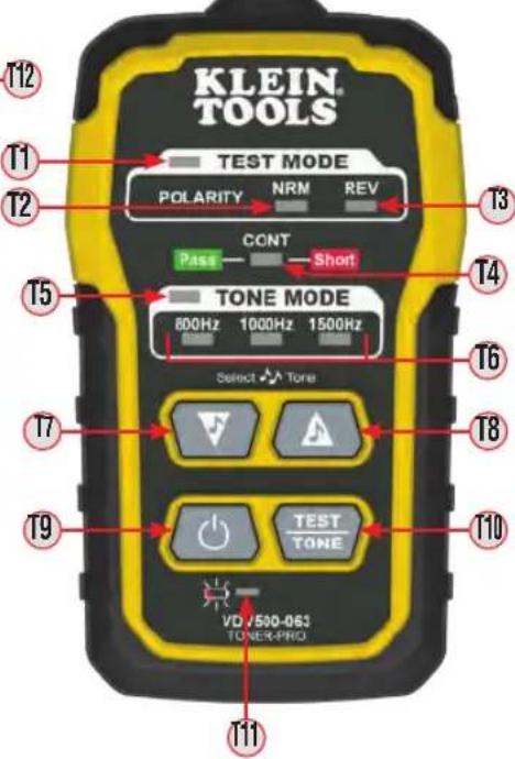
T1 TEST MODE Indicator
T9 Power On/Off Button
T2 'NRM' (Normal) Polarity Indicator
T10 TEST/TONE Button
T3 'REV' (Reverse) Polarity Indicator
T11 Battery Status Indicator
T4 'CONT' (Continuity) Indicator
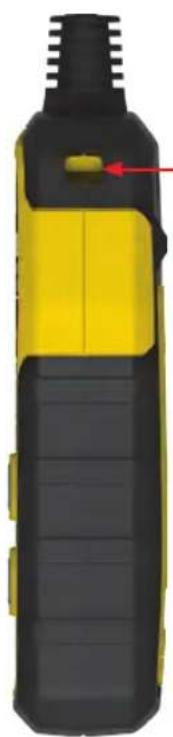
T12 Lanyard Slot
T5 TONE MODE Indicator
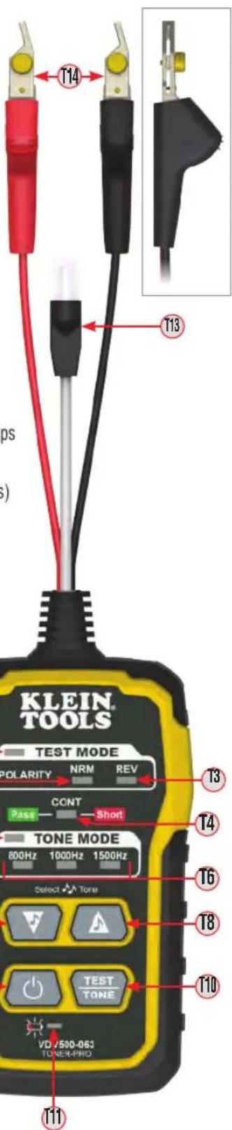
T13 RJ11 Test Plug
T6 Tone Frequency Indicators
T14 ABN (Angled Bed-of-Nails) Test Clips
T7 Tone Mode Down selector button
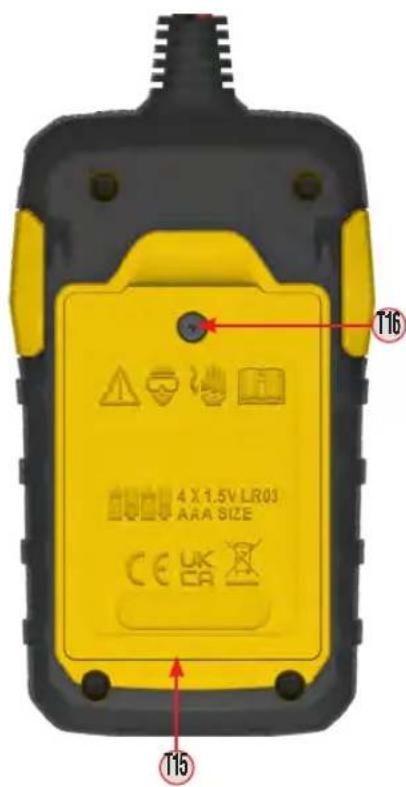
T15 Battery Cover
T8 Tone Mode Up selector button
T16 Battery Cover Screw (No. 2 Phillips)
GENERAL SPECIFICATIONS - VDV500-123 PROBE-PRO
The Klein Tools VDV500-123 Probe-Pro is a professional-series tone tracer, featuring an inductive probe with a speaker for amplification, and an LED light for use in dark spaces. It also features a headphone jack for use in extreme noise environments.
- Operating Altitude: 6562^ (2000 m) maximum
Relative Humidity: 10% to 90% , non-condensing - Operating Temp: 14^ to 122^ F( -10^ to50^ C)
Storage Temp: -4^ to 140^ (-20^ to 60^)
Dimensions: 1.75^ × 8.88^ × 1.13^ (44 × 226 × 29 mm)
Weight: 5.7 oz (161.6 g) including batteries - Battery Type: 4 × 1.5V AAA Alkaline
Battery Life: Active: 25 hours
Standby/Storage: 3 years
- Auto Power-Off: After 10 minutes of inactivity
Specifications subject to change.
FEATURE DETAILS
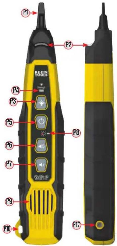
P1 Replaceable Inductive Polymer Tip (VDV999-068)
P2Worklight
P3Worklight On/Off Button
P4Signal Strength Indicator
P5Power On/Off Button
P6Volume Increase Button
P7Volume Decrease Button
P8 Battery Status Indicator
P9Speaker
P10 Lanyard Slot
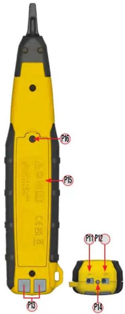
P11 * " (Negative) Terminal
P12 * " (Positive) Terminal
P13 Terminal Release Buttons
P14 Verification Indicator
P15 Battery Cover
P16 Battery Cover Screw (No. 2 Phillips)
P17 3.5 mm Headphone Jack*
*CAUTION: Excessive volume can cause permanent hearing damage. Use as low a volume as possible.
WARNING
To ensure safe operations and service of the instruments, follow these instructions. Failure to observe these warnings can result in fire, electric shock, severe injury or death.
- The Toner-Pro and Probe-Pro are designed for use on extra-low voltage cabling systems (less than 60 volts) for testing when NOT energised.
- The maximum voltage across ABN Test Clips of the Toner-Pro is 60 volts in Test mode, and 20 volts in Continuity mode. Connecting the Probe-Pro to live mains AC power may damage it and pose a safety hazard for the user.
DO NOT use instruments if they are wet, as it could pose a shock hazard.
DO NOT use instruments if they are damaged in any way. - Turn off instruments and disconnect all ABN Test Clips before attempting to replace batteries.
- The battery door must be in place and secure before you operate the instrument.
- DO NOT open the case, other than the battery compartment.
OPERATING INSTRUCTIONS
READ ALL INSTRUCTIONS BEFORE OPERATING AND RETAIN INSTRUCTIONS FOR FUTURE REFERENCE
CONTINUITY TEST
The Toner-Pro transmits frequencies on non-energised wires only. When the Toner-Pro is turned on, a continuity test will be performed to determine if the 2 wires to be traced are in close proximity to each other, without a conductive path between them. The 'CONT' Indicator 14 will illuminate green to indicate a pass. Attach the red and black ABN Test Clips 14 to the wires to be tested. If the resistance of the circuit is less than 10k , the 'CONT' Indicator 14 will illuminate red, indicating a short, and no toning can occur. If the "CONT" Indicator is illuminated green, a tone can be generated and you may proceed.
SELECTING TONE FREQUENCY
The Toner-Pro defaults to the 800 Hz frequency setting when powered on. Use the Tone Mode Up and Tone Mode Down selector buttons to change the frequency. The Tone Frequency Indicators will display the frequency being transmitted. If an alternating tone is selected, the two respective Tone Frequency Indicators will blink. Tones will cycle through the available frequencies in a continuous loop when a selector button is pressed repeatedly.
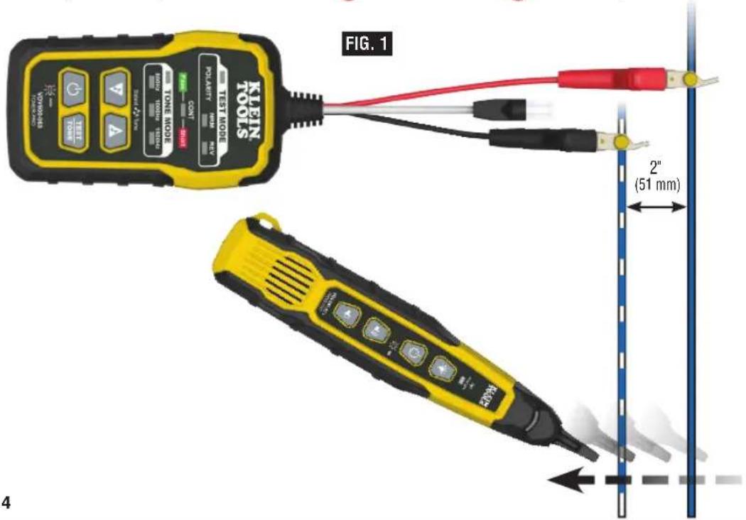
TRACING PAIRED WIRES (FIG.1)
- Connect the Toner-Pro's red ABN Test Clip to one of the wires of the pair to be traced. Connect the black ABN Test Clip to the other wire to be traced.
- Turn Toner-Pro on by pressing the Power On/Off button 19.
- Check the 'CONT' Indicator (4). If it is illuminated green, you may proceed.
- Select the preferred tone setting using the Tone Mode Up (18) and/or Tone Mode Down (17) selector buttons.
- Turn the Probe-Pro on by pressing the Power On/Off button P5.
- At the far end of the cable, spread the wires apart at least 2^ (51 mm). If possible,
- Use the Probe-Pro to scan the cable's wire pairs. Move the Probe-Pro's tip slowly across the wires (FIG. 1). The Probe-Pro's volume will increase as it approaches the toned pair. When the Probe-Pro's volume is high over the first wire, low in the middle (between) the two wires, and high over the second wire, you have located the pair of wires you are tracing. Use the Volume Increase P6 and Volume Decrease P7 buttons to adjust the volume.
OPERATING INSTRUCTIONS
VERIFYING TONED PAIRS (FIG. 2)
- To verify you have found the toned pair, connect the Toner-Pro's ABN Test Clips or RJ11 Test Plug to one end of the cable and initiate a tone.
- On the other end of the cable, remove approximately 2mm (3 / 32^ ) of the outer jacket of each of the wires believed to be the toned pair.
- Insert the wire connected to the red ABN Test Clip 14 to the "+" (Positive) Terminal P2, and the wire currently in the black ABN Test Clip 14 to the "-" (Negative) Terminal P1. To access the terminals, press their respective Terminal Release buttons P3, insert the wire(s) and release (FIG. 2). The Verification Indicator P14 will illuminate when the correct pair is inserted.

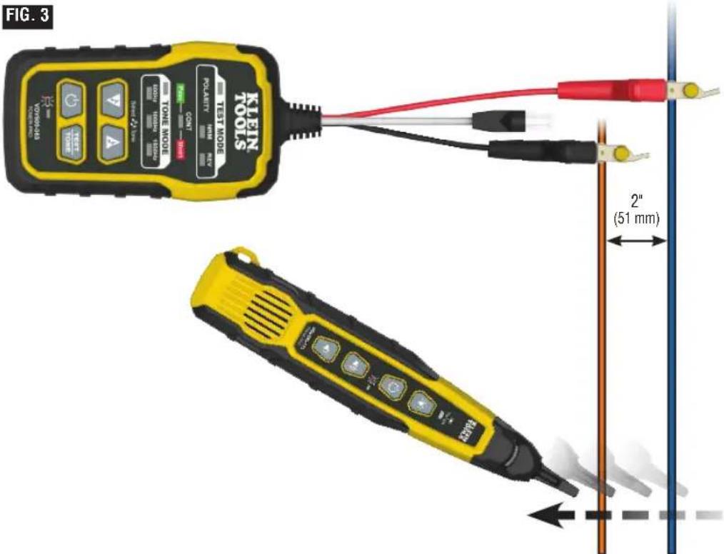
TRACING NON-PAIRED WIRES (FIG. 3)
- Connect the Toner-Pro's red ABN Test Clip to the wire to be traced.
- Connect the black ABN Test Clip to another wire in the cable, but preferably not in the same pair (connect to the ground, if available). When tracing a shielded cable, connect the red ABN Test Clip to the outer shield, and the black ABN Test Clip to the center conductor or ground.
- Turn Toner-Pro on by pressing the Power On/Off button (T9).
- Check the 'CONT' Indicator 14. If it is illuminated green, you may proceed.
- Turn the Probe-Pro on by pressing the Power On/Off button P5.
- Select the preferred tone setting using the Tone Mode Up or Tone Mode Down selector buttons.
- At the far end of the cable, spread the wires at least 2^ (51 mm) apart, if possible.
- Use the Probe-Pro to scan the cable's wire pairs. Move the Probe-Pro's tip (P) slowly across the wires. The Probe-Pro's volume will increase as it approaches the toned wire.
OPERATING INSTRUCTIONS
RJ11 / RJ12 / RJ45 TESTING
The Toner-Pro has an RJ11 Test Plug that can be used in place of the ABN clips to transmit the tone. The RJ11 plug works with RJ11, RJ12 or RJ45 jacks. The red and black ABN contacts are replaced by the 2 center conductors of the inserted plug, i.e. Pins 2 and 3 for RJ11, Pins 3 and 4 for RJ12, and Pins 4 and 5 for RJ45. Use the Probe-Pro to locate the toned wires at the far end of the cable, as described in the TRACING PAIRED WIRES section.
POLARITY AND VOLTAGE PRESENCE TESTING
The Toner-Pro may be used to test the polarity and type of voltage that is present.
- Press the Power On/Off button on the Toner-Pro.
- Press the TEST/TONE Select button button The 'TEST MODE' indicator will illuminate.
- Connect the ABN Test Clips (14), or insert the RJ11 Test Plug (13).
- Check the 'CONT' Indicator (T4). If it is illuminated green, you may proceed.
-
The 'NRM' (Normal) Polarity Indicator (2) will illuminate if the red ABN Test Clip (14) is connected to the POTS (Plain Old Telephone Service) in the proper orientation. The 'REV' (Reverse) Polarity Indicator (13) will illuminate if the wires are reversed.
-
The 'NRM' (Normal) Polarity Indicator (2) will illuminate when the black ABN Test Clip detects a higher voltage than the red ABN Test Clip.
The 'REV' (Reverse) Polarity Indicator T3 will illuminate when the red ABN Test Clip detects a higher voltage than the black ABN Test Clip.
The 'NRM' (Normal) Polarity Indicator and 'REV' (Reverse) Polarity Indicator will both illuminate when an AC voltage is present. - When the RJ11 Test Plug is used, the 'NRM' (Normal) Polarity Indicator will illuminate on a correctly wired and powered POTS (Plain Old Telephone Service) phone jack.
NOTE: The POTS (Plain Old Telephone Service) colour code convention (black/positive, red/negative) is the opposite of the multimeter colour code convention (red/positive, black/negative).
USING THE PROBE'S WORKLIGHT
The Probe-Pro has a worklight (P2) to aid in illuminating dark or low-light work areas. Press the Worklight On/Off Button (P3) to turn the light on and off.
MAINTENANCE
BATTERY REPLACEMENT
When the Low Battery Indicator P1 or P8 blinks, the batteries must be replaced.
- Turn off instrument(s) before attempting to replace the batteries.
- Loosen screw 116, P16 on the battery cover 115, P15.
- Remove and properly dispose of four 1.5V AAA batteries.
- Install new batteries (note the proper polarity).
- Replace battery cover and fasten securely with the screw.
To avoid risk of electric shock, do not operate while battery door is removed.
PROBE-PRO TIP REPLACEMENT (KLEIN CAT. NO. VDV999-068)
The tip P1 of the Probe-Pro is replaceable if damaged. To remove and replace tip:
- Turn tip 1/4 turn and pull gently to remove.
- Insert new tip with key in the proper orientation and push gently.
- Rotate 1/4 turn to lock into place.
CLEANING
Be sure instrument is turned off and wipe with a clean, dry lint-free cloth. Do not use abrasive cleaners or solvents.
STORAGE
Remove the batteries when instrument is not in use for a prolonged period of time. Do not expose to high temperatures or humidity. After a period of storage in extreme conditions exceeding the limits mentioned in the GENERAL SPECIFICATIONS section, allow the equipment to return to normal operating conditions before using.
WARRANTY
Do not place equipment and its accessories in the trash. Items must be properly disposed of in accordance with local regulations. Prior to disposal of this product, please contact Klein Tools for proper disposal options.
CUSTOMER SERVICE
KLEIN TOOLS, INC.
450 Bond Street
Lincolnshire, IL 60069
800-553-4676
customerservice@kleintools.com
www.kleintools.com
NOTES

P11 Terminal "-" (negative)
P12 Terminal "+" (positivo)