Ranger TDR VDV501-090 - Measuring equipment Klein Tools - Free user manual and instructions
Find the device manual for free Ranger TDR VDV501-090 Klein Tools in PDF.


User questions about Ranger TDR VDV501-090 Klein Tools
0 question about this device. Answer the ones you know or ask your own.
Ask a new question about this device
Download the instructions for your Measuring equipment in PDF format for free! Find your manual Ranger TDR VDV501-090 - Klein Tools and take your electronic device back in hand. On this page are published all the documents necessary for the use of your device. Ranger TDR VDV501-090 by Klein Tools.
USER MANUAL Ranger TDR VDV501-090 Klein Tools
The Klein Tools Ranger™ TDR is a portable time domain reflectometer (TDR) and voice-data-video cable tester. It measures cable length calibrates Nominal Velocity of Propagation (NVP) values, finds faults in cables, and provides built-in tone generation for cable tracing.
• ± (1% + 3 ft. / 1 m) length accuracy
- Stores up to two NVP values.
- Displays length reading in feet or meters.
- Extra large seven-segment, back-lit LCD screen.
- Tests most types of copper cable including data, voice, video, lamp wire, siamese, and NM cables.
• Discovers NVP values for cables with known length.
- Automatic pre-test voltage checks.
- Identifies cable faults
- Tone generator with selectable tone cadence to easily trace cables with an analog tone probe (not included).
- Conserves power and supports long battery life with auto power off.
GENERAL SPECIFICATIONS
- Dimensions: 6.8" x 3.15" x 1.3" (17.3 x 8.0 x 3.3 cm)
• Weight: 12.0 oz. (340 grams) with batteries - Operating Temperature: 32° to 122°F (0° to 50°C)
• Storage Temperature: -4°F to 140°F (-20° to 60°C)
• Humidity: 10% to 90%, non-condensing - Altitude: 10000 ft. (3050 m) maximum
- Input Protection: 400V peak 50/60Hz AC or DC
- Voltage Warning: At maximum of Safety Extra Low Voltage limits (60V peak AC or DC). Measurement continues while warning is displayed.
• Battery Low Level: Approximately 4V - Battery Life: 4 AA alkaline batteries
- Standby: 4 years
• Active: 15 hours (average)
• Measurement Method: Spread Spectrum Time Domain Reflectometry
• NVP (VOP) Range: 20 to 99.9% - NVP Accuracy Range: ± (1% + 3 ft. / 1 m); with known NVP and consistent cable parameters
• Common Cable Length Ranges:
• Coaxial: 0 to 2000 ft. (0 to 610 m)
• Data: 0 to 1500 ft. (0 to 457 m)
• Electrical: 0 to 1000 ft. (0 to 305 m) - Tone Generation: Constant output amplitude of 3Vpp, 4 cadences centered around 1 kHz

WARNINGS
To ensure safe operation and service of the tester, follow these instructions. Failure to observe these warnings can result in severe injury or death.
- The Ranger™ TDR should NOT be used on energized cabling systems.
- Connecting the instrument to voltages above the Safety Extra Low Voltage range of less than 60V peak AC or DC may pose a safety hazard to the user
- Internal components of the Ranger™ TDR are protected up to 400V peak AC or DC. Connecting the instrument to voltages above this range may pose a safety hazard to the user and the instrument.
| SYMBOLS: | |
| Warning: Potential for personal injuryCaution: Potential for damage or destruction to equipment. | |
| Always wear approved eye protection. | |
| Do NOT use on energized circuits | |
| CE | Conformité Européenne. Conforms with European Economic Area directives. |
| Do not place equipment and its accessories in the trash.Items must be properly disposed of in accordance with local regulations | |
| DEFINITIONS: | |
| Nominal Velocity of Propagation (NVP) | Also known as the Velocity of Propagation (VOP), Velocity Factor (VF) and Wave Propagation Speed, NVP is the speed of an electrical signal traveling through a cable, measured as a percentage of the speed of light |
| Safety Extra Low Voltage (SELV) | SELV is a rating determined by the International Electrotechnical Commission that defines safe voltage standards when using electronic devices. SELV is 60V for DC systems and 42.5V RMS for AC Systems. |
| F-Connector | An F-Connector is a common connector for a coax cable, o tt.en associated with televisions. |
| Spread Spectrum Time Domain Reflectometry (TDR-SS) | Spread spectrum is the technological foundation of cell phone communications and is used to transmit small signals in high noise environments. By combining spread spectrum with TDR technology, TDR-SS allows for a length test on cables without interference from voltage. |
OVERVIEW
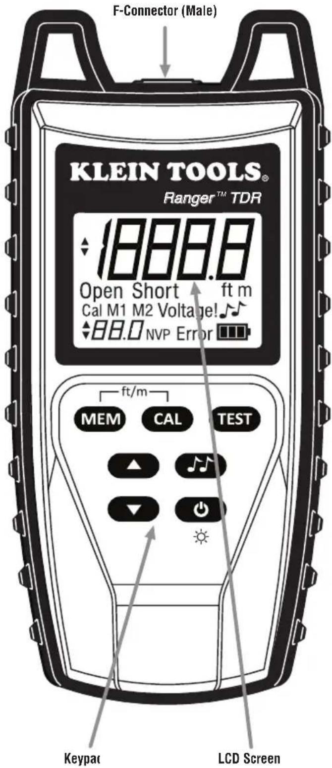
text_image
F-Connector (Male) KLEIN TOOLS® Ranger™ TDR 1888.8 Open Short ft m Cal M1 M2 Voltage! 88.0 NVP Error ft/m MEM CAL TEST ▲ ↓ ▼ ↓ Keypac LCD ScreenACCESSORIES
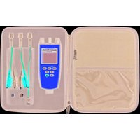
The VDV501-815 kit includes several accessories to facilitate testing on almost all popular cable types. See Preparing to Test Cables section to learn how to connect the accessories for specific applications.
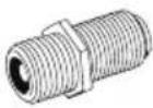 | F-Connector Barrel Connector Couple(Female to Female) |
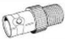 | F-Connector to BNC Connector Couple(Female to Female) |
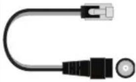 | F-Connector to RJ45 Jack Adapter(Male to Male |
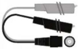 | F-Connector to Alligator Clips Adapter(Male to Male |
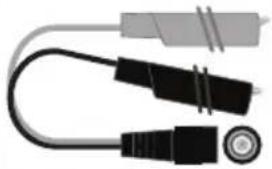 | BNC Connector to Alligator Clips Adapter(Male to Male |
LCD SCREEN ICONS
text_image
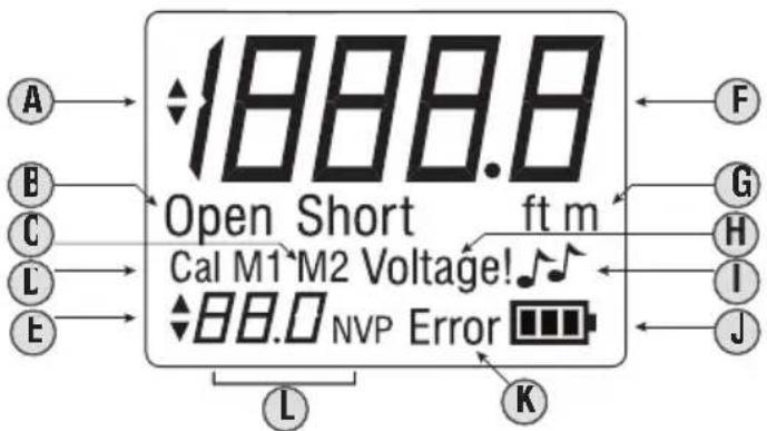
A B C L E 1888.8 Open Short ft m Cal M1 M2 Voltage! 88.0 NVP Error L K F G H I JA. Length Adjustment Indicator: Indicates the cable length can be adjusted during Calibration Mode. Indicates tone style can be changed in Tone Mode
B. Cable Status: Open or Short is displayed if the cable has a fault.
C. Memory Storage Locations: Indicates the currently selected NVP memory location.
D. Calibration Mode: Indicates that Calibration Mode is active
E. NVP Adjustment Indicator: Indicates that the currently selected NVF memory location has been edited.
F. Primary Display: Shows numerical cable length. Shows tone cadence in Tone Mode
G. Unit of Measurement: Indicates the unit of measurement (feet or meters) currently being used to display the measurement.
H. Voltage Warning: Indicates voltage above the SELV rating of 60v peak AC or DC has been detected on the cable. NOTE: The absence of the "Voltage!" symbol DOES NOT necessarily mean that there are 0 volts on the line.
I. Tone Mode: Indicates the unit is in Tone Mode
J. Battery Life Indicator: Indicates the estimated battery life of the unit. Flashes when batteries require replacement.
K. Error Message: Indicates an error in a test or calibration. In Tes Mode, the cable is terminated or there is excessive signal loss. In Calibration Mode, the NVP value calculated is outside the required range (20 to 99.9%).
L. NVP Value: Shows the current NVP value used to make length calculations.
KEYPAC
text_image
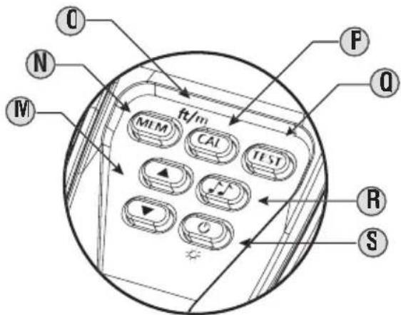
O N M ft/m M/M CAI FT ST R S O F Q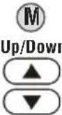 | In Calibration Mode: the buttons are used to adjust the measured cable length to match the known cable length within the range of 25 to 1000 ft. (10 m to 300 m).In Tone Mode: the buttons select a cadence (HI, LO, HL1 HL2) |
 | The Memory button is used to store up to two NVP values for testing purposes.Short presses of the Memory button toggles between the two memory storage locations: M1 and M2.A long press (two seconds) of the button stores an NVP value in the selected storage location. |
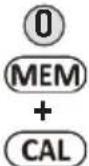 | A long press (two seconds) of the Memory and Calibration buttons simultaneously toggles between units of measurement (feet and meters). |
C  n n | The Calibration button allows you to discover the NVP value based on an inputted cable length.Short presses of the Calibration button adjust cable length in increments of 50 ft. or 20 m within the range of 50 ft. to 1000 ft. or 20 m to 300 m.A long press (two seconds) of the Calibration button aborts Calibration mode and enters Test Mode |
 | The Test button initiates length testing on the connected cableA short press runs a single test on demand.A long press (two seconds) of the button starts loop testing. Pressing any button (except Power) stops loop testing (or the unit turns off a ft.er 3 minutes). |
 | The Ione button allows you to trace cables by soundA short press of the button transmits an audio tone from the unit through the connected cable.Subsequent presses of the Ione button toggle between test and Ione modesAn analog tone probe (not included) must be used in order to hear the tone. |
 | A long press (two seconds) of the Power button powers on the RangerTM TDR.Subsequent presses of the button toggle the backlight on and offA long press (two seconds) of the button powers off the RangerTM TDR |
STARTUP AND SHUTDOWN
TURNING THE UNIT ON AND OFF
- Press and hold the power button for two seconds to turn the unit on.
- The unit will immediately run a length test at startup.
- Press and hold the power button for two seconds to turn the unit off
AUTO POWER OFF
The Ranger™ TDR will automatically turn off a ft.er a period of inactivity in order to conserve battery power. The time until auto power off depends on which mode the unit is in.
- Test Mode: 1 minute
- Loop Test Mode: 3 minutes
- Tone Mode: 15 minutes
- Calibration Mode: 1 minute
GENERAL TESTING PROCEDURES
PREPARING TO TEST CABLES
It is important that the included accessories be used correctly in order to ensure quick and accurate testing.

IMPORTANT SAFETY INFORMATION
- The cable to be tested should be evaluated for the presence of voltage with a voltage measurement device by a qualified professional before beginning work with the Ranger™ TDR. The cable should be disconnected from any voltage source before beginning work.
- The "Voltage!" icon appears on the LCD when the voltage on the cable surpasses the SELV rating of 60V peak AC or DG. The Ranger™ TDR should be disconnected from the cable immediately if the "Voltage!" icon appears. The Ranger™ TDR should NOT be used on energized cabling systems
- Testing Coax Cable:
1 Connect the F-connector coupler (barrel connector) to the input port of the Ranger™ TDR by carefully screwing it in.
2. The cable to be tested should be terminated with an F-connecto on the end that will be attached to the Ranger™ TDR.
3 The opposite end of the cable to be tested should be le ft. unterminated OR terminated with an F-connector but le ft. unconnected
4. Attach the cable to be tested to the Ranger™ TDR by carefully screwing or pushing the terminated end onto the F-connector coupler, depending on what type of F-connector was used to terminate the cable.
- Testing Twisted Pair (8P8C) Cable
1 Connect the F-connector coupler (barrel connector) to the input port of the Ranger™ TDR by carefully screwing it in.
2. The cable to be tested should be terminated with a female RJ45 jack on the end that will be attached to the Ranger™ TDR.
3 The opposite end of the cable to be tested should be le ft unterminated OR terminated with an RJ45 plug or jack but le ft. unconnected
4. Attach the included F-connector-to-male-RJ45 plug adapter to the Ranger™ TDR
5. Attach the RJ45 plug adapter end to the female RJ45 jack of the cable being tested.
- Testing Two-Conductor Cable
1 Connect the F-connector coupler (barrel connector) by carefully screwing it into the input port of the Ranger™ TDR.
2 The cable to be tested should have a pair of exposed conductors that run side-by-side. This includes inner pairs on twisted pair cable
3. The opposite end of the cable to be tested should be le ft. oper (unconnected)
4. Attach the included F-connector to alligator clips adapter to the Ranger™ TUR
5. Securely attach the alligator clips to the exposed conductors of the cable to be tested.
- Testing BNC Cable
1 Connect the BNC coupler (barrel connector) by carefully screwing it into the input port of the Ranger™ TDR.
2. The cable should be terminated with a BNC connector
3. The opposite end of the cable to be tested should be left unterminated OR terminated with a BNC connector but left unconnected
4. Attach the BNC connector of the cable to be tested to the female BNC connector on the Ranger™ TDR.
OBTAINING NVP VALUES
There are three ways to obtain NVP values for a cable:
- The NVP can usually be obtained by checking the cable specifications or contacting the manufacturer
- The NVP can be estimated based on the type of cable (RG6, Cat5e, etc.) using the chart on page 13.
- The NVP can be calculated using a known length of the cable that will be used during testing
- Calculating an NVP:
1 Prepare a length of the same type of cable for which you need to determine the NVP
2. The Ranger™ TDR can calculate an NVP from a test cable length of 25 - 1000 ft. (10 - 300 m). Longer test lengths will give more accurate results. It is recommended to use at least 50 ft. (20 m). 50 ft. (20 m) is the default setting in Calibration Mode.
-
Determine the physical length of the test cable length. Use the markings on the cable, a tape measure, laser distance meter, etc.
-
Connect the test cable length to the Ranger™ TDR as described in "Preparing to Test Cables" section
-
Press the Power button on the Ranger™ TDR
-
Press the Calibration button
-
Select the unit of measurement (feet or meters) by pressing and holding the Memory and Calibration buttons at the same time
-
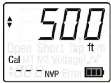
Enter the known cable length using the Calibration button and Up and Down buttons. The Calibration button adds 50 ft. (20 m) with each press. The Up and Down buttons increase or decrease the distance by 1 ft. or 1m per press.
-
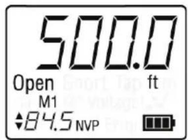
Press the test button. A ft. er a few seconds, the calculated NVF will appear in the bottom le ft. corner of the LCD.
-
Press and hold the Memory button to save the new NVP in the current storage location (M1 or M2).
-
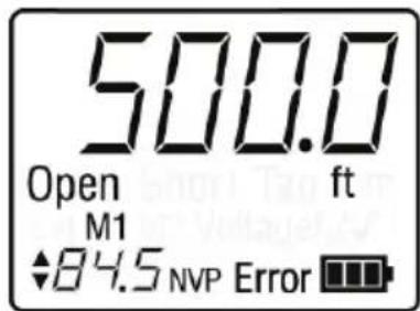
If the calculated NVP is outside of the range 20 to 99.9, the LCD will display "Error".
text_image
500 ft Cal - - - NVPStep 6
text_image
500.0 Open ft M1 ♦84.5 NVPStep 9
text_image
500.0 Open ft M1 ♦84.5 NVP Error ■■■Step 11
SETTING NVP VALUES
The NVP value must be set correctly in order to obtain an accurate length measurement from the device.
- Manually Setting NVP:
1 Press the Power button. The unit will start up in Test Mode
2. Use the Up and Down buttons to set the NVP value shown in the lower left hand corner of the LCD scree
3. Pressing and holding a button will change the value more quickly
- Saving NVP:
1 The Ranger™ TDR has two storage locations for NVP values.
2 Press the Memory button repeatedly to toggle between memory locations
3. Set the memory location using the procedure noted above.
4. Press and hold the Memory button. The up and down arrows shown on the LCD screen will disappear when the new value has been stored.
5. Recall a stored value by pressing the Memory button until the desired memory location is shown
TESTING CABLE & DETERMINING LENGTH
Once a cable's NVP value has been set, the cable length can be determined using Test Mode. As stated in Preparing to Test Cables, the cable to be tested should be le ft. open on the opposite end from the tester. A cable terminated with an impedance closely matching the characteristic impedance of the cable can produce inaccurate test results
- Testing Cable
1 Attach the cable to be tested as instructed in Preparing to Les Cables section
2. Note that the connection to the cable to be tested should be as short as possible to ensure the Ranger™ TDR does not see the impedance continuity at the attachment point as a fault
3. Determine the correct NVP value for the cable to be tested as instructed in Obtaining NVP Values section
4. Set the NVP value as instructed in Setting NVP Values section
5. Turn the unit on by pressing the Power button.
6. Change the unit of measurement if necessary by pressing and holding the Memory and Calibration buttons at the same time
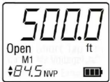
7. Press the Test button once. A ft.er a moment, the calculated length of the cable will appear in the upper right hand corner of the screen
8. The screen will display "Short" if the two conductors are directly connected or have a low resistance connection between them. The length will be shown up to the shorted point.
9. The screen will display "Open" if the two conductors are no directly connected or have a high resistance connection between them. This is the normal condition for performing length testing. If there is an unexpected open condition along the length of the cable, only the length up to that point will be displayed.
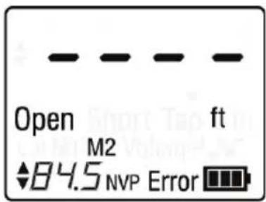
10 The screen will display "Error" and show dashes instead of the length if an error condition has occurred. This could be because the cable is improperly terminated or there has been excessive signal loss
text_image
500.0 Open ft M1 ♦84.5 NVPStep 7
text_image
Open M2 84.5 NVP ErrorStep 10
- Using Loop Testing Mode:
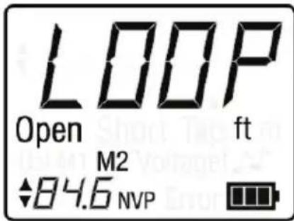
The Ranger™ TDR can run continuous tests when set to Loop Mode. Loop Mode can help when testing long cable runs susceptible to signal loss, and enabling you to test multiple cables without having to press the Test button each time
1 While in Test Mode, press and hold the Test button
2. The screen will momentarily flash "LOOP", then run a test every two seconds and display the results.
3. Pressing any other button except the Power button exits Loop Mode
text_image
LOOP Open ft M2 84.6 NVPStep 1
TONING CABLE
Tone Mode can be used to trace cables by sound. A cadence is emitted from the unit through a connected cable. The cadence can only be detected and amplified with an analog tone probe, such as the Klein Tools PROBEplus tone tracing probe (VDV500-060) not included, and is not audible to the human ear without the probe.
- Enabling Tone Mode
1 Attach the cable to be toned as instructed in Preparing to Tes Cables section
2. Press the Power button
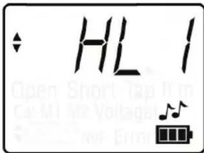
3. Press the Tone button (two music notes)
4. Press the Up button or Down button to switch cadences (HI, LO HL1, HL2)
5. Use a tone probe to trace the cable being toned
6. See the tone probe's instruction manual for more information or how to tone cables.
text_image
HL 1 Open Short Tap In Can M1 Me Voltage on ErrisStep 3
COMMON NVP VALUES
Below is a list of NVP values for common types
| Cable Type | NVP | Range |
| Coaxial Cable | ||
| RG5E | 65.4 | 64.5 - 66.4 |
| RG5E | 83.9 | 83.0 - 85.0 |
| RG6L | 84.6 | 83.5 - 85.5 |
| RG6 Quad Shield | 84.9 | 84.0 - 86.0 |
| Phone Cable | ||
| CAT3 4-Pair | 67.3 | 65.5 - 68.0 |
| CAT3 3 Pair CMX | 67.5 | 66.5 - 68.1 |
| 24/25 Pair CAT3 | 64.0 | 63.0 - 65.0 |
| Data Cable | ||
| CAT5e (Orange/Orange White | 65.9 | 65.0 - 67.0 |
| CAT5e STF | 65.2 | 64.2 - 66.2 |
| CAT5e ft.F | 73. | 72.1 - 74.1 |
| 24/25 Pair CAT5e | 71.0 | 70.0 - 72.0 |
| CAT6 | 68.8 | 67.5 - 69.5 |
| Electrical Cable | ||
| 10/2 NM Coilec | 68.8 | 68.0 - 70.0 |
| 10/2 NM Uncoilec | 71.2 | 70.2 - 72.2 |
| 12/2 NM Coilec | 67. | 66.0 - 68.0 |
| 12/2 NM Uncoilec | 73.2 | 72.0 - 74.0 |
| 12/3 NM Coilec | 63.7 | 63.0 - 64.5 |
| 12/3 NM Uncoilec | 70.6 | 69.5 - 71.5 |
| 12/3 NM Twisted Coilec | 68.4 | 67.8 - 69.4 |
| 12/3 NM Twisted Uncoilec | 68.4 | 67.8 - 69.0 |
| 14/2 NM Coilec | 66.4 | 65.0 - 68.6 |
| 14/2 NM Uncoilec | 71.9 | 71.0 - 73.0 |
| 14/3 NM Coilec | 64.8 | 64.0 - 65.5 |
| 14/3 NM Uncoilec | 68.6 | 67.5 - 69.5 |
| Security Cable | ||
| 12/2 Fire PLN | 59.9 | 59.0 - 60.9 |
| 16/2 Fire PVC | 65.9 | 65.0 - 67.0 |
| 18/4 Fire PLN | 60.4 | 59.5 - 61.5 |
| 18/6 Fire PLN | 61.6 | 60.5 - 62.5 |
| 14/2 Audio Cable | 71.0 | 70.0 - 72.0 |
BATTERY REPLACEMENT
- Remove single screw in the middle of the back of the Ranger™ TDR with a #1 Phillips head screwdriver. Remove battery door
- Remove and recycle exhausted batteries.
- Acquire 4 AA 1.5V alkaline batteries (IEC LR6, ANSI/NEDA 15A).
- Insert batteries into the battery compartment observing the polarity marked inside the case
- Replace battery door and screw, taking care not to over-tighten it
WARRANTY
Turn instrument off and disconnect any cables. Clean the instrument by using a damp cloth. Do not use abrasive cleaners or solvents.
STORAGE
Remove the batteries when instrument is not in use for a prolonged period of time. Do not expose to high temperatures or humidity. A ft.er a period of storage in extreme conditions exceeding the limits mentioned in the Specifications section, allow the instrument to return to normal operating conditions before using it.
DISPOSAL / RECYCLE
Do not place equipment and its accessories in the trash. Items must be properly disposed of in accordance with local regulations.
Prior to disposal of this product, please contact Klein Tools for proper disposal options.
CUSTOMER SERVICE
KLEIN TOOLS, INC.
450 Bond Street
Lincolnshire, IL 60069
1-800-553-4676
www.kleintools.com
VDV501-090
text_image
A B C L E 1888.8 Open Short ft m Cal M1 M2 Voltage! BB.0 NVP Error L K F G H I Jtext_image
HL 1 Open Short Tap from Call MT M2 Voltage MPT EndPaso 3
VALORES COMUNES DE NVP
MANUAL DE INSTRUÇÕES
TDR Ranger™
PORTUGUÊS
text_image
A B C L E 1888.8 Open Short ft m Cal M1 M2 Voltage! BB.0 NVP Error L K F G H I Jtext_image
Q N M ft/m MEM CAL TEST P Q R Stext_image
HL 1 Open Short Tap Turn Cal M1 M2 Voltage New ErmEtapa 3
VALORES COMUNS DA NVP
text_image
A B C L E 1888.8 Open Short ft m Cal M1 M2 Voltage! BB.0 NVP Error L K F G H I Jtext_image
HL 1 Open Short Tap from Cut M1 M2 Voltage Power ErrorÉtape 3