
EBS 180 F - Grinder Eibenstock - Free user manual and instructions
Find the device manual for free EBS 180 F Eibenstock in PDF.

| Product type | Concrete grinder (grinder) |
| Brand | Eibenstock |
| Model | EBS 180 F |
| Dimensions (approx.) | 600 x 400 x 350 mm |
| Weight | 10,5 kg |
| Power supply | 230 V / 110 V, 50/60 Hz |
| Power consumption | 2500 W (230 V) / 2300 W (110 V) |
| No-load speed | 6000 min⁻¹ |
| Rated speed | 8500 min⁻¹ |
| Max. disc diameter | 180 mm |
| Arbor bore | 22,2 mm |
| Protection class | II (double insulation) |
| Protection rating | IP 20 |
| Noise level | > 85 dB(A) |
| Vibration level | < 2,5 m/s² |
| Main functions | Grinding of concrete floors, leveling, removal of coatings |
| Overload protection | Electronic and thermal with automatic shutdown |
| Vacuum connection | Yes, for industrial vacuum cleaner class M (DSS 35 M iP) |
| Maintenance and cleaning | Clean the air vents, replace the disc regularly |
| Spare parts | Diamond grinding wheels ∅ 180 mm (concrete, leveling, PCD), brush crown, vacuum cleaner |
| Repairability | Eibenstock after-sales service, repair by qualified personnel |
Frequently Asked Questions - EBS 180 F Eibenstock
User questions about EBS 180 F Eibenstock
0 question about this device. Answer the ones you know or ask your own.
Ask a new question about this device
Download the instructions for your Grinder in PDF format for free! Find your manual EBS 180 F - Eibenstock and take your electronic device back in hand. On this page are published all the documents necessary for the use of your device. EBS 180 F by Eibenstock.
USER MANUAL EBS 180 F Eibenstock
Original Instructions....14 - 23
natural_image
Green and black industrial machine tool with handle and control knob (no visible text or symbols)EBS 180 F
DEUTSCH
Wichtige Hinweise
natural_image
Close-up of a black electronic device with a yellow indicator light and screw base (no visible text or symbols)natural_image
Close-up of mechanical components with a green and black component, no visible text or symbolsnatural_image
Close-up of a green cylindrical object with black plastic clips and white directional arrows indicating movement or assembly (no text or symbols)natural_image
Close-up of a mechanical assembly with green and black components, featuring a metallic clamp and a white arrow pointing to a small circular component (no text or symbols visible)natural_image
Close-up of a mechanical component with three circular arrows indicating rotational changes (no text or symbols)natural_image
Close-up of a black mechanical component with a cylindrical shaft inserted, against a white background (no text or symbols visible)natural_image
Close-up of a mechanical component with circular holes and a metal tool inserted (no visible text or symbols)natural_image
Simple line drawing of a trash bin with no text or symbolsLothar Lässig
General Manager
25.02.2020
Frank Markert
Head of Engineering
Important Safety Instructions
Important instructions and warning notices are allegorized on the machine by means of symbols:


Before you start working, read the operating instructions of the machine.
Work concentrated and carefully. Keep your work-place clean and avoid dangerous situations.
In order to protect the user, take precautions.
During work you should wear ear protectors, goggles, dust mask, protective gloves and sturdy work clothes!


Use ear protection
Wear safety goggles
Wear a dust mask
Wear protective gloves
Warning notices


Warning of general danger
Warning of dangerous voltage
Warning of hot surface
Danger of being ripped or cut
Specifications
Concrete Grinder EBS 180 F
| Rated voltage | 230 V | 110 V |
| Power input | 2500 W | 2300 W |
| Order no. | 0634H000 | 0634L000 |
Frequency: 50/60 Hz
Rated speed: 6000 rpm
No-load speed: 8500 rpm
Max. disc diameter: 180 mm
Spindle: ∅ 22,2 mm
Protection class: I
Degree of protection: IP 20
Net weight: about 10,5 kg
Interference suppression: EN 55014 and EN 61000
Available special accessories:
| Item | Order no. |
| Diamond Grinding Wheel ∅ 180mm (Concrete) 37112000 | |
| Diamond Grinding Wheel ∅ 180mm (Screed) 37111000 | |
| Diamond Grinding Wheel ∅ 180mm (PCD) 37119000 | |
| Brush rim with removable segment | 37227000 |
| Industrial Vacuum Cleaner DSS 35 M iP | 09917000 |
Content of Delivery
Concrete grinder with diamond grinding wheel (concrete), tool kit and operating instructions in a carton.
Application for Indented Purpose
The concrete grinder is indented for professional use.
With an appropriate grinding wheel, the tool may be used for smoothing rough concrete, removing residual mud, joint fillers and tile adhesives.
Only use grinding wheels recommended by the manufacturer.
These have a small weight and a high concentricity.
Using other grinding wheels can cause an overload of the machine or damage of the bearings, danger to the user and loss of warranty. The machine may be used exclusively in conjunction with a grinding wheel and a vacuum cleaner of dust category M.

Safe work with the machine is only possible if you read this operating instruction and follow the instructions contained strictly. Additionally, the general safety instructions of the leaflet supplied with the tool must be observed. Prior to the first use, the user should absolve a practical training. Save all warnings and instructions for future reference.
If the mains cable gets damaged or cut during the use, do not touch it, but instantly pull the plug out of the socket. Never use the tool with damaged mains cable.
The tool must neither be wet nor used in humid environment.
- Do not use the tool in an environment with danger of explosion.
- Do not grin into asbestos-containing materials.
■ Modifications of the tool are prohibited. - Never use the machine without dust guard.
Use machine with partly removed dust guard in corners only.
For other applications the dust guard must always be closed.
- Always check the tool, cable and plug before use and plug before use. Have damages only repaired by specialists.
Insert the plug into the socket only when the tool switch is off.
- When you work outside, the machine has to be used with a fault-current circuit breaker with max. 30 mA.
- The machine should only work under supervision of somebody.
Plug and switch the machine off if it is not under supervision, in case of putting up and stripping down the machine, in case of voltage drop or when fixing or mounting an accessory.
- Switch the machine off if it stops for whatever reason. You avoid that it starts suddenly and not under supervision.
- Don't use the machine if a part of the housing is damaged or in case of damages on the switch, the cable or plug.
- Pay attention that the speed indicated on the grinding wheel meets or is higher than the max. speed indicated on the machine.
- Grinding wheels have to be stored and used carefully according to the instructions of the producer.
- Check the accessories before use. Do not use any products which are broken, cracked or damaged in another way.
■ Before use, make sure that the tool is correctly fixed and fastened.
Let it run idle for about 30 seconds in a safe position. If considerable vibrations occur or if other defects are recognised, switch off immediately.
■ Always lead the mains and extension cable as well as the extraction hose to the back away from the machine.
■ Power tools have to be inspected by a specialist in regular intervals.
■ Never carry the machine at its cable.
- Do not touch rotating parts.
- Persons under 16 years of age are not allowed to use the tool.
- During use, the operator and other persons standing nearby have to wear suitable ear protectors, a dust mask, safety goggles and protective gloves.


■ Make sure that persons in the work space are not endangered by particles flying around.
- Keep the handles dry, clean and free of oil and grease.
- During operation, always hold the tool with both hands.
- Attention! The tool still runs for a little while after the machine was switched off.
For further safety instructions, please refer to the enclosure!
Electrical Connection
Before starting the machine check the correspondence between voltage and frequency according to the data mentioned on the identification plate.
Voltage differences from + 6 % and - 10 % are allowed.
The grinder is made in protection class I.
Only use extension cables with a sufficient cross-section. A cross-section which is too small could cause a considerable drop in performance and an overheating of machine and cable.
The tool includes a start-up speed limiter to prevent fast expulsion fuses from unintended responding.
Switching on and off

natural_image
Close-up of a black electronic device with a yellow indicator light and screw base (no visible text or symbols)Put the plug in the mains.
Tilt slightly the machine, so that the grinding wheel runs free when switching on.
Switch ON / OFF switch to "I".
Before switch off tilt slightly the machine again and switch the ON / OFF switch to "0".
Before put down the machine, wait until the grinding wheel stops.

Attention!
In case of every stop of the machine or a power cut, the lock-on button has to be released immediately by pressing the ON/OFF switch. So you can avoid an unintentional restart of the machine (physical hazard).
Dust Extraction
Dust which occurs during your work is hazardous to health. That is why the concrete grinder must be used with a vacuum cleaner (dust category M), and a dust mask has to be worn. The suitable Wet/Dry Vacuum Cleaner DSS 35 M iP is available as accessory. It can directly be attached to the connection on end of the guide rod.
Inclination adjustment

natural_image
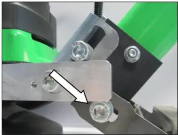
Close-up of a mechanical assembly with green and black components, no visible text or symbolsThe floor guiding device can be adjusted in its inclination to your needs.
For this open the screw (arrow) and turn the floor guiding device in the desired position and close the two screws.
Adjustable handle
natural_image
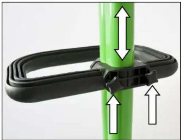
Close-up of a green cylindrical object with black plastic clips and white directional arrows indicating movement or force (no text or symbols)The height-adjustable handle can be adjusted continuously depending on the user.
For this purpose loosen the two wing bolts (arrows).
Push the handle to the desired position and close the thumbscrews.
Chassis adjustment
To achieve an optimal grinding result the chassis has to be adjusted in its position to the current inclination adjustment of the floor guiding device and to the rate of wear on the grinding wheel (height of the grinding segments).
natural_image
Close-up of mechanical components with a white arrow pointing to a green component (no text or symbols visible)For this open the screw (arrow) right at the machine. Make sure that the grinding wheel rests holohedral on the floor by pressing on the motor. Now control that the wheels of the chassis rest on the floor.
If necessary adjust the position of the chassis and close the screws.
Instruction for Use
Connect the device to a suitable dust extraction.
Before switching on the device, tilt the floor guiding device backwards so that the grinding disc rotates freely when switched on. Switch the device on and place the grinding disc straight onto the surface to be ground. Guide the concrete grinder evenly over the surface of the floor. Before completing the grinding work, again tilt the floor guiding device backwards until the grinding disc rotates freely and then switch the device off.
Check in regular intervals the wear of the diamond segments.
On hard floorings you need some abrasive dust on the surface to sharpen the diamond segments faster.
Therefore it suffices to switch off the connected industrial vacuum cleaner for few seconds.
Or the surface can be wetted during grinding to reduce the "polishing" of the diamond segments.
Take care that approx. 20 to 30 per cent of the grinding wheel works on the already grinded surface to avoid scoring and to get a better grinding result.
This method also avoids polishing of the diamond segments.
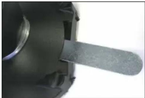
For grinding works right into edges of the wall one segment of the dust guard can be removed by means of the chucking device.
For it loosen both wing screws and pull the segment off (see fig. page 20).
Attention! All other grinding works have to be done with the complete closed dust guard.
Changing the Diamond Grinding Wheel


Attention!
The grinding wheel might heat up enormously during operation. You could burn your hands or get cut or ripped by the segments.
Therefore, always use protective gloves when changing the grinding wheel.
Before any work on the tool, disconnect the plug from the mains!
natural_image
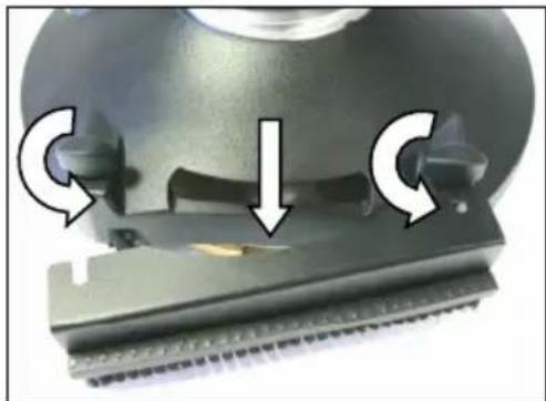
Close-up of a mechanical component with three circular arrows indicating rotational changes (no text or symbols)First of all, the detachable hood segment has to be removed.
For it loosen both wing screws and pull the segment off.
natural_image
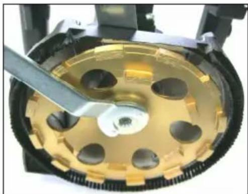
Close-up of a mechanical component with a metallic rod inserted, no visible text or symbolsThrough the opening at the protection cover now you can hold up the driving disc between gearbox and grinding wheel by using the jaw wrench 32 included in the delivery.
natural_image
Close-up of a mechanical component with a metallic tool inserted, showing internal circular features and a central hole (no text or symbols visible)Use the face spanner to unscrew the driving nut.
Then remove the mounted grinding wheel respectively mount the new one.
The assembly works the other way round!
After mounting the grinding wheel, let the machine run for a short period of time and in a safe position. If the machine does not run easily, stop working immediately.
Use only original accessory!
Overload Protection
In order to protect the operator, motor and drill bit, the concrete grinder is equipped with an electronic and thermal overload protection.
Thermal: In case of permanent overload, a thermocouple protects the motor against destruction. In this case, the tool switches off automatically and can only be restarted after a certain cooling period (approx. 2 minutes). The cooling period depends on the heating of the motor winding and the ambient temperature.
Electronic: In case of overload, the electronic facility will deenergize the tool. After discharge and reengagement one can drill again.
Care and Maintenance
Before the beginning of maintenance or repair works you have to disconnect the plug from the mains.
Repairs may be executed only by appropriately qualified and experienced personnel. After every repair the machine has to be inspected by an electric specialist.
Due to its design, the machine needs a minimum of care and maintenance. However, the following points always have to be observed:
■ Always keep the power tool and the ventilation slots clean.
- During work, please pay attention that no particles get inside the machine.
- In case of failure, a repair has to be carried out by an authorised service workshop.
Our after-sales service responds to your questions concerning maintenance and repair of your product as well as spare parts. EIBENSTOCK's application service team will gladly answer questions concerning our products and their accessories.
Environmental Protection

Raw material recycling instead of waste disposal
To avoid damages on transportation, the power tool has to be delivered in a sturdy packing. Packaging as well as unit and accessories are made of recyclable materials and can be disposed accordingly.
The tool's plastic components are marked according to their material, which makes it possible to remove environmental friendly and differentiated because of available collection facilities.
Only for EU countries
Do not dispose of electric tools together with household waste material!

natural_image
Symbol of a trash bin with crossed lines indicating no waste or discharge (no text or labels)In observance of the European Directive 2012/19/EU on waste electrical and electronic equipment and its implementation in accordance with national law, electric tools that have reached the end of their life must be collected separately and returned to an environmentally compatible recycling facility.
Noise Emission / Vibration
The indication of noise emission is measured according to DIN 45 635, part 21. The level of acoustic pressure on the work place could exceed 85 dB (A); in this case protection measures must be taken.

Wear ear protectors!
The typical hand-arm vibration is below 2.5 m/s ^2 . Measured values determined according to EN 60 745.
The declared vibration emission level represents the main applications of the tool. However if the tool is used for different applications, with different accessories or poorly maintained, the vibration emission may differ. This may significantly increase the exposure level over the total working period. An estimation of the level of exposure to vibration should also take into account the times when the tool is switched off or when it is running but not actually doing the job. This may significantly reduce the exposure level over the total working period.
Identify additional safety measures to protect the operator from the effects of vibration such as: maintain the tool and the accessories, keep the hands warm, organisation of work patterns.
Dust protection
Dust from material such as paint containing lead, some wood species, minerals and metal may be harmful. Contact with or inhalation of the dust may cause allergic reactions and/or respiratory diseases to the operator or bystanders.
Certain kinds of dust are classified as carcinogenic such as oak and beech dust especially in conjunction with additives for wood conditioning (chromate, wood preservative). Material containing asbestos must only be treated by specialists.
- Where the use of a dust extraction device is possible it shall be used.
- To achieve a high level of dust collection, use industrial vacuum cleaner DSS 35 M iP for wood and/or minerals together with this tool.
■ The work place must be well ventilated. - The use of a dust mask of filter class P2 is recommended.
Warranty
According to our general terms of delivery for business dealings, suppliers have to provide to companies a warranty period of 12 months for redhibitory defects (to be documented by invoice or delivery note).
Damages due to natural wear, overstressing or improper handling are excluded from this warranty.
Damages due to material defects or production faults shall be eliminated free of charge by either repair or replacement.
Complaints will be accepted only if the tool is returned in non-dismantled condition to the manufacturer or an authorized Eibenstock service centre.

Declaration of Conformity
We declare under our sole responsibility that the product described under “Technical Data” is in conformity with the following standards or standardization documents:
EN 60 745
according to the provisions of the directives 2011/65/EU, 2014/30/EU, 2006/42/EG
Technical file (2006/42/EC) at:
Lothar Lässig
General Manager
Frank Markert
Head of Engineering
25.02.2020
Subject to change without notice.
natural_image
Close-up of a black electrical connector with a yellow indicator light and mounting holes (no text or symbols visible)natural_image
Close-up of a mechanical component with green and black parts, featuring a white arrow pointing to a small metallic bolt (no text or symbols visible)natural_image
Close-up of a green cylindrical object with black plastic clips and white directional arrows indicating movement or assembly (no text or symbols)natural_image
Close-up of mechanical components with a white arrow pointing to a metallic bracket (no visible text or symbols)natural_image
Close-up of a mechanical component with three circular arrows indicating rotation or adjustment (no text or symbols)natural_image
Close-up of a mechanical component with a metallic blade and circular base (no visible text or symbols)natural_image
Close-up of a mechanical component with circular holes and a metal tool inserted (no visible text or symbols)natural_image
Symbol of a trash bin crossed out by two diagonal lines (no text or labels)Lothar Lässig
General Manager
25.02.2020
Frank Markert
Head of Engineering
natural_image
Close-up of a black electronic device with a yellow indicator light and screw base (no visible text or symbols)natural_image
Close-up of a mechanical assembly with green and black components, featuring screws and metal brackets (no visible text or symbols)natural_image
Close-up of a green cylindrical object with black plastic clips and white directional arrows indicating movement or assembly (no text or symbols)natural_image
Close-up of mechanical components with a white arrow pointing to a metallic bracket (no visible text or symbols)natural_image
Close-up of a mechanical component with three circular arrows indicating rotation or adjustment, no visible text or symbols.natural_image
Close-up of a metallic mechanical component with a flat blade and circular base (no visible text or symbols)natural_image
Close-up of a mechanical component with a metallic tool inserted, showing internal circular cavities and a central hole (no text or symbols visible)natural_image
Simple line drawing of a trash bin with no text or symbolsLothar Lässig
General Manager
25.02.2020
Frank Markert
Head of Engineering
natural_image
Close-up of a black electronic device with a yellow indicator light on its surface (no visible text or symbols)natural_image
Close-up of mechanical components with green and black parts, no visible text or symbolsnatural_image
Close-up of a green cable with black plastic clamps and white directional arrows indicating compression or movement (no text or symbols)natural_image
Close-up of mechanical components with a white arrow pointing to a green component (no text or symbols visible)For at gøre dette, skal du løsne to fingerskruer (pil).
natural_image
Close-up of a mechanical component with three circular arrows indicating rotation or adjustment (no text or symbols)natural_image
Close-up of a mechanical component with a metallic rod inserted, no visible text or symbolsnatural_image
Close-up of a mechanical component with a metallic tool inserted, showing internal circular features and a central hole (no text or symbols visible)natural_image
Simple line drawing of a trash bin with no text or symbolsLothar Lässig
General Manager
25.02.2020
Frank Markert
Head of Engineering
Ihr Fachhändler
Your distributor


- DEUTSCH
- Wichtige Hinweise
- Important Safety Instructions
- Specifications
- Concrete Grinder EBS 180 F
- Content of Delivery
- Application for Indented Purpose
- Electrical Connection
- Switching on and off
- Attention!
- Dust Extraction
- Inclination adjustment
- Adjustable handle
- Chassis adjustment
- Instruction for Use
- Changing the Diamond Grinding Wheel
- Overload Protection
- Care and Maintenance
- Before the beginning of maintenance or repair works you have to disconnect the plug from the mains.
- Environmental Protection
- Raw material recycling instead of waste disposal
- Only for EU countries
- Noise Emission / Vibration
- Wear ear protectors!
- Dust protection
- Warranty
- Declaration of Conformity
Brand : Eibenstock
Model : EBS 180 F
Category : Grinder