ARXP25M5V1B - Air Conditioning DAIKIN - Free user manual and instructions
Find the device manual for free ARXP25M5V1B DAIKIN in PDF.


User questions about ARXP25M5V1B DAIKIN
0 question about this device. Answer the ones you know or ask your own.
Ask a new question about this device
Download the instructions for your Air Conditioning in PDF format for free! Find your manual ARXP25M5V1B - DAIKIN and take your electronic device back in hand. On this page are published all the documents necessary for the use of your device. ARXP25M5V1B by DAIKIN.
USER MANUAL ARXP25M5V1B DAIKIN
Installation manual R32 split series
1.1 About this document 3
2 About the box 3
2.1 Outdoor unit.. 3
2.1.1 To unpack the outdoor unit 3
2.1.2 To remove the accessories from the outdoor unit.... 4
3 Preparation 4
3.1 Preparing the installation site 4
3.1.1 Installation site requirements of the outdoor unit .... 4
3.1.2 Additional installation site requirements of the outdoor unit in cold climates
3.2 Preparing refrigerant piping 5
3.2.1 Refrigerant piping requirements 5
3.2.2 Refrigerant piping length and height difference 5
3.2.3 Refrigerant piping insulation 5
4 Installation 5
4.1 Opening the units 5
4.1.1 To open the outdoor unit 5
4.2 Mounting the outdoor unit 5
4.2.1 To provide the installation structure.. 5
4.2.2 To install the outdoor unit.. 6
4.2.3 To provide drainage 6
4.2.4 To prevent the outdoor unit from falling over 6
4.3 Connecting the refrigerant piping 6
4.3.1 About connecting the refrigerant piping 6
4.3.2 Precautions when connecting the refrigerant piping... 7
4.3.3 To connect the refrigerant piping to the outdoor unit .. 7
4.4 Checking the refrigerant piping 7
4.4.1 To check for leaks.. 7
4.4.2 To perform vacuum drying 7
4.5 Charging refrigerant 7
4.5.1 About charging refrigerant 7
4.5.2 About the refrigerant 8
4.5.3 To determine the additional refrigerant amount.... 8
4.5.4 To determine the complete recharge amount. 8
4.5.5 To charge additional refrigerant 8
4.5.6 To fix the fluorinated greenhouse gases label 9
4.6 Connecting the electrical wiring 9
4.6.1 Specifications of standard wiring components.. 9
4.6.2 To connect the electrical wiring on the outdoor unit.... 9
4.7 Finishing the outdoor unit installation 10
4.7.1 To finish the outdoor unit installation 10
4.7.2 To close the outdoor unit 10
5 Commissioning 10
5.1 Checklist before commissioning 10
5.2 Checklist during commissioning 10
5.3 To perform a test run 10
5.4 Starting up the outdoor unit 10
6 Disposal 11
6.1 Overview: Disposal 11
6.2 To pump down 11
6.3 To start and stop forced cooling 11
6.3.1 To start/stop forced cooling using the indoor unit ON/OFF switch 11
6.3.2 To start/stop forced cooling using the indoor unit user interface 11
7 Technical data 12
7.1 Wiring diagram 12
1 About the documentation
1.1 About this document

INFORMATION
Make sure that the user has the printed documentation and ask him/her to keep it for future reference.
Target audience
Authorised installers
Documentation set
This document is part of a documentation set. The complete set consists of:
- General safety precautions:
- Safety instructions that you MUST read before installing
- Format: Paper (in the box of the outdoor unit)
- Outdoor unit installation manual:
- Installation instructions
- Format: Paper (in the box of the outdoor unit)
- Installer reference guide:
- Preparation of the installation, reference data,...
- Format: Digital files on http://www.daikineurope.com/support-and-manuals/product-information/
Latest revisions of the supplied documentation may be available on the regional Daikin website or via your dealer.
The original documentation is written in English. All other languages are translations.
Technical engineering data
- A subset of the latest technical data is available on the regional Daikin website (publicly accessible).
- The full set of latest technical data is available on the Daikin extranet (authentication required).
2 About the box
2.1 Outdoor unit
2.1.1 To unpack the outdoor unit
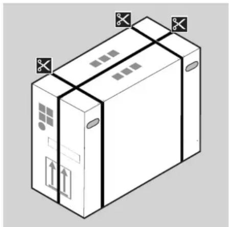
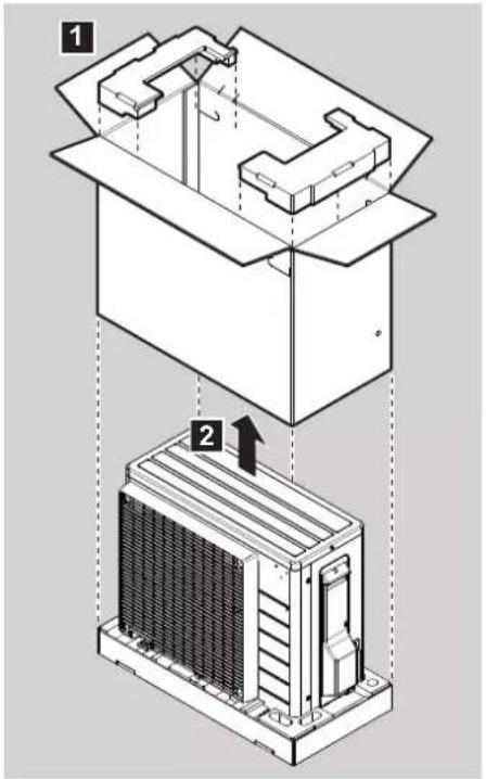
2.1.2 To remove the accessories from the outdoor unit
1 Lift the outdoor unit.
2 Remove the accessories at the bottom of the package.
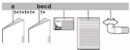
a General safety precautions
b Outdoor unit installation manual
c Fluorinated greenhouse gases label
d Multilingual fluorinated greenhouse gases label
e Drain plug (located on the bottom of the packing case)
3 Preparation
3.1 Preparing the installation site

WARNING
The appliance shall be stored in a room without continuously operating ignition sources (example: open flames, an operating gas appliance or an operating electric heater).
3.1.1 Installation site requirements of the outdoor unit
Mind the following spacing guidelines:
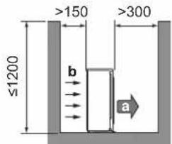
a Air outlet
Air inlet
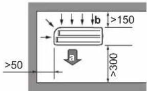
(mm)(mm)
It is recommended to install a baffle plate when the air outlet is exposed to wind.
It is recommended to install the outdoor unit with the air inlet facing the wall and NOT directly exposed to the wind.
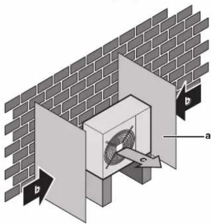
a Baffle plate
b Prevailing wind direction
c Air outlet
3.1.2 Additional installation site requirements of the outdoor unit in cold climates
Protect the outdoor unit against direct snowfall and take care that the outdoor unit is NEVER snowed up.
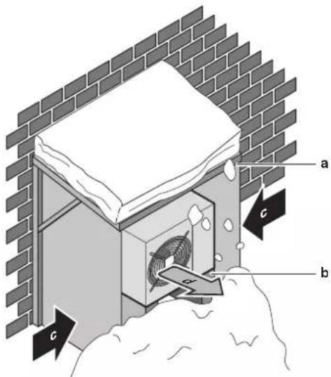
a Snow cover or shed
b Pedestal
c Prevailing wind direction
d Air outlet
In any case, provide at least 300mm of free space below the unit.
Additionally, make sure the unit is positioned at least 100mm above
the maximum expected level of snow
outdoor unit" on page 5 for more details.
In heavy snowfall areas it is very important to select an installation
site where the snow will NOT affect the unit. If lateral snowfall is
possible, make sure that the heat exchanger coil is NOT affected by
possible, make sure that the most exchangeable coin is not affected by the snow. If necessary, install a snow cover or shed and a pedestal.
See also
4.2 Mounting the outdoor unit [5]
3.2 Preparing refrigerant piping
3.2.1 Refrigerant piping requirements
- Piping material: Phosphoric acid deoxidised seamless copper.
- Piping diameter:
| Liquid piping Ø6.4 mm (1/4") | |
| Gas piping Ø9.5 mm (3/8") |
- Piping temper grade and thickness:
| Outer diameter (Ø) | Temper grade Thickness (t) (a) | |
| 6.4 mm (1/4") Annealed (O) ≥0.8 mm | ||
| 9.5 mm (3/8") Annealed (O) | ||
(a) Depending on the applicable legislation and the unit's
maximum working pressure (see "PS High" on the unit
name plate), larger piping thickness might be required.
3.2.2 Refrigerant piping length and height
difference
| What? Distance | |
| Maximum allowable pipe length | 15 m |
| Minimum allowable pipe length | 1.5 m |
| Maximum allowable height difference | 12 m |
3.2.3 Refrigerant piping insulation
| Pipe outer diameter (Øp) | Insulation inner diameter (Øi) | Insulation thickness (t) |
| 6.4 mm (1/4") | 8~10 mm | ≥10 mm |
| 9.5 mm (3/8") | 12~15 mm |
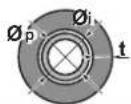
If the temperature is higher than 30^ and the humidity is higher than RH 80% , the thickness of the insulation materials should be at least 20 mm to prevent condensation on the surface of the insulation.
4 Installation
4.1 Opening the units
4.1.1 To open the outdoor unit



4.2 Mounting the outdoor unit
4.2.1 To provide the installation structure
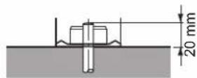
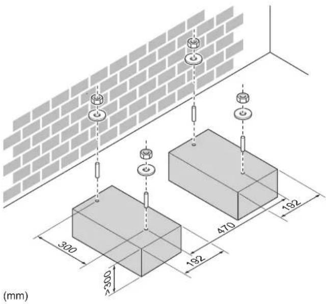
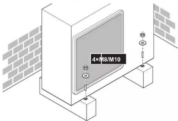
Prepare 4 sets of M8 or M10 anchor bolts, nuts and washers (field supply).
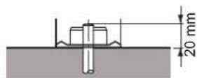
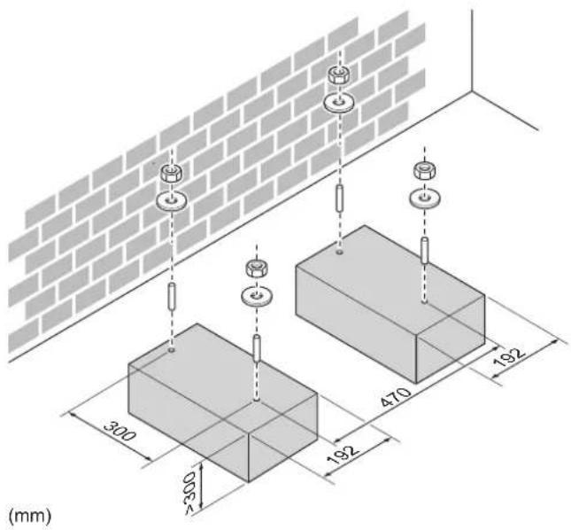
In any case, provide at least 300mm of free space below the unit. Additionally, make sure the unit is positioned at least 100mm above the maximum expected level of snow. In this case, it is recommended to construct a pedestal.
4.2.2 To install the outdoor unit
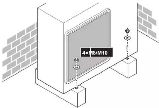
4.2.3 To provide drainage

NOTICE
If the unit is installed in a cold climate, take adequate measures so that the evacuated condensate CANNOT freeze.

INFORMATION
For information on the available options, contact your dealer.

NOTICE
Provide at least 300mm of free space below the unit. Additionally, make sure the unit is positioned at least 100mm above the expected level of snow.
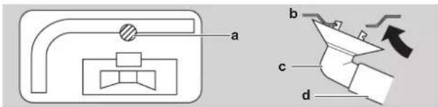
1 Use a drain plug for drainage.
2 Use a 016 mm hose (field supply).
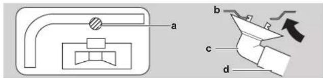
a Drain port
b Bottom frame
c Drain plug
d Hose (field supply)
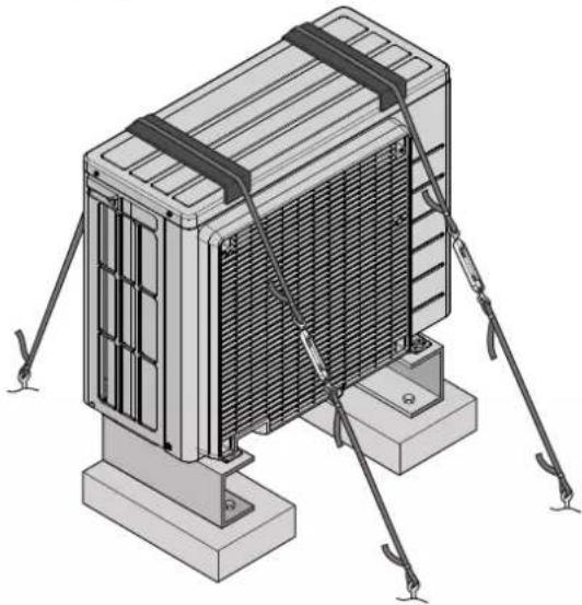
4.2.4 To prevent the outdoor unit from falling over
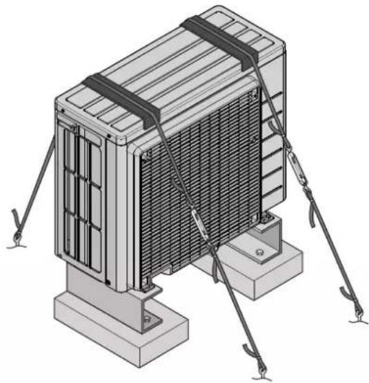
In case the unit is installed in places where strong wind can tilt the unit, take following measure:
1 Prepare 2 cables as indicated in the following illustration (field supply).
2 Place the 2 cables over the outdoor unit.
3 Insert a rubber sheet between the cables and the outdoor unit to prevent the cables from scratching the paint (field supply).
4 Attach the ends of the cables and tighten them.
4.3 Connecting the refrigerant piping

DANGER: RISK OF BURNING
4.3.1 About connecting the refrigerant piping
Before connecting the refrigerant piping
Make sure the outdoor and indoor unit are mounted.
Typical workflow
Connecting the refrigerant piping involves:
- Connecting the refrigerant piping to the indoor unit
- Connecting the refrigerant piping to the outdoor unit
Insulating the refrigerant piping -
Keeping in mind the guidelines for:
-
Pipe bending
Flaring pipe ends - Using the stop valves
4.3.2 Precautions when connecting the refrigerant piping

DANGER: RISK OF BURNING

CAUTION
- Use the flare nut fixed to the main unit.
- To prevent gas leakage, apply refrigeration oil only to the inside of the flare. Use refrigeration oil for R32.
- Do NOT reuse joints.

WARNING
Connect the refrigerant piping securely before running the compressor. If the refrigerant piping is NOT connected and the stop valve is open when the compressor is run, air will be sucked in. This will cause abnormal pressure in the refrigeration cycle, which may result in equipment damage and even injury.
4.3.3 To connect the refrigerant piping to the outdoor unit
- Piping length. Keep field piping as short as possible.
- Piping protection. Protect the field piping against physical damage.
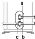
1 Connect the liquid refrigerant connection from the indoor unit to the liquid stop valve of the outdoor unit.
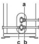
a Liquid stop valve
b Gas stop valve
c Service port
2 Connect the gas refrigerant connection from the indoor unit to the gas stop valve of the outdoor unit.

NOTICE
It is recommended that the refrigerant piping between indoor and outdoor unit is installed in a ducting or the refrigerant piping is wrapped with finishing tape.
4.4 Checking the refrigerant piping
4.4.1 To check for leaks

NOTICE
Do NOT exceed the unit's maximum working pressure (see "PS High" on the unit name plate).

NOTICE
Make sure to use a recommended bubble test solution from your wholesaler. Do not use soap water, which may cause cracking of flare nuts (soap water may contain salt, which absorbs moisture that will freeze when the piping gets cold), and/or lead to corrosion of flared joints (soap water may contain ammonia which causes a corrosive effect between the brass flare nut and the copper flare).
1 Charge the system with nitrogen gas up to a gauge pressure of at least 200 kPa (2 bar). It is recommended to pressurize to 3000 kPa (30 bar) in order to detect small leaks.
2 Check for leaks by applying the bubble test solution to all connections.
3 Discharge all nitrogen gas.
4.4.2 To perform vacuum drying
1 Vacuum the system until the pressure on the manifold indicates -0.1MPa (-1 bar).
2 Leave as is for 4-5 minutes and check the pressure:
| If the pressure... Then. | . |
| Does not change There is no m | misture in the system. This procedure is finished. |
| Increases There is moisture in the | the system. Go to the next step. |
3 Vacuum the system for at least 2 hours to a manifold pressure of -0.1MPa (-1 bar).
4 After turning the pump OFF, check the pressure for at least 1 hour.
5 If you do NOT reach the target vacuum or CANNOT maintain the vacuum for 1 hour, do the following:
- Check for leaks again.
- Perform vacuum drying again.

NOTICE
Make sure to open the stop valves after installing the refrigerant piping and performing vacuum drying. Running the system with the stop valves closed may break the compressor.
4.5 Charging refrigerant
4.5.1 About charging refrigerant
The outdoor unit is factory charged with refrigerant, but in some cases the following might be necessary:
| What | When |
| Charging additional refrigerant | When the total liquid piping length is more than specified (see later). |
| Completely recharging refrigerant | Example: • When relocating the system. • After a leak. |
Charging additional refrigerant
Before charging additional refrigerant, make sure the outdoor unit's external refrigerant piping is checked (leak test, vacuum drying).

INFORMATION
Depending on the units and/or the installation conditions, it might be necessary to connect electrical wiring before you can charge refrigerant.
Typical workflow - Charging additional refrigerant typically consists of the following stages:
1 Determining if and how much you have to charge additionally.
2 If necessary, charging additional refrigerant.
3 Filling in the fluorinated greenhouse gases label, and fixing it to the inside of the outdoor unit.
Completely recharging refrigerant
Before completely recharging refrigerant, make sure the following is done:
1 All refrigerant is recovered from the system.
2 The outdoor unit's external refrigerant piping is checked (leak test, vacuum drying).
3 Vacuum drying on the outdoor unit's internal refrigerant piping is performed.

NOTICE
Before completely recharging, perform vacuum drying on the outdoor unit's internal refrigerant piping as well.
Typical workflow - Completely recharging refrigerant typically consists of the following stages:
1 Determining how much refrigerant to charge.
2 Charging refrigerant.
3 Filling in the fluorinated greenhouse gases label, and fixing it to the inside of the outdoor unit.
4.5.2 About the refrigerant
This product contains fluorinated greenhouse gases. Do NOT vent gases into the atmosphere.
Refrigerant type: R32
Global warming potential (GWP) value: 675

NOTICE
In Europe, the greenhouse gas emissions of the total refrigerant charge in the system (expressed as tonnes CO_2 equivalent) is used to determine the maintenance intervals. Follow the applicable legislation.
Formula to calculate the greenhouse gas emissions: GWP value of the refrigerant × Total refrigerant charge [in kg] / 1000
Please contact your installer for more information.

WARNING: FLAMMABLE MATERIAL
The refrigerant inside this unit is mildly flammable.

WARNING
The appliance shall be stored in a room without continuously operating ignition sources (example: open flames, an operating gas appliance or an operating electric heater).

WARNING
- Do NOT pierce or burn refrigerant cycle parts.
- Do NOT use cleaning materials or means to accelerate the defrosting process other than those recommended by the manufacturer.
- Be aware that the refrigerant inside the system is odourless.

WARNING
The refrigerant inside the unit is mildly flammable, but normally does NOT leak. If the refrigerant leaks in the room and comes in contact with fire from a burner, a heater, or a cooker, this may result in fire, or the formation of a harmful gas.
Turn off any combustible heating devices, ventilate the room, and contact the dealer where you purchased the unit.
Do NOT use the unit until a service person confirms that the part from which the refrigerant leaked has been repaired.
4.5.3 To determine the additional refrigerant amount
| If the total liquid piping length is... | Then... |
| ≤10 m Do NOT add additional refrigerant. | |
| >10 m | R=(total length (m) of liquid piping-10 m)×0.020 R=Additional charge (kg) (rounded in units of 0.01 kg) |

INFORMATION
Piping length is the one-way length of liquid piping.
4.5.4 To determine the complete recharge amount

INFORMATION
If a complete recharge is necessary, the total refrigerant charge is: the factory refrigerant charge (see unit name plate) + the determined additional amount.
4.5.5 To charge additional refrigerant

WARNING
- Only use R32 as refrigerant. Other substances may cause explosions and accidents.
R32 contains fluorinated greenhouse gases. Its global warming potential (GWP) value is 675. Do NOT vent these gases into the atmosphere. - When charging refrigerant, ALWAYS use protective gloves and safety glasses.
Prerequisite: Before charging refrigerant, make sure the refrigerant piping is connected and checked (leak test and vacuum drying).
1 Connect the refrigerant cylinder to the service port.
2 Charge the additional refrigerant amount.
3 Open the gas stop valve.
4.5.6 To fix the fluorinated greenhouse gases label
1 Fill in the label as follows:
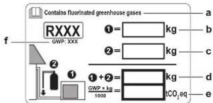
a If a multilingual fluorinated greenhouse gases label is delivered with the unit (see accessories), peel off the applicable language and stick it on top of a.
b Factory refrigerant charge: see unit name plate
c Additional refrigerant amount charged
d Total refrigerant charge
e Greenhouse gas emissions of the total refrigerant charge expressed as tonnes CO_2 equivalent
f GWP = Global warming potential

NOTICE
In Europe, the greenhouse gas emissions of the total refrigerant charge in the system (expressed as tonnes CO_2 equivalent) is used to determine the maintenance intervals. Follow the applicable legislation.
Formula to calculate the greenhouse gas emissions: GWP value of the refrigerant × Total refrigerant charge [in kg] / 1000
2 Fix the label on the inside of the outdoor unit near the gas and liquid stop valves.
4.6 Connecting the electrical wiring

DANGER: RISK OF ELECTROCUTION

WARNING
- All wiring MUST be performed by an authorised electrician and MUST comply with the applicable legislation.
- Make electrical connections to the fixed wiring.
- All components procured on-site and all electrical construction MUST comply with the applicable legislation.

WARNING
ALWAYS use multicore cable for power supply cables.

WARNING
If the supply cord is damaged, it MUST be replaced by the manufacturer, its service agent or similarly qualified persons in order to avoid a hazard.

WARNING
Do NOT connect the power supply to the indoor unit. This could result in electrical shock or fire.

WARNING
- Do NOT use locally purchased electrical parts inside the product.
- Do NOT branch the power supply for the drain pump, etc. from the terminal block. This could result in electrical shock or fire.

WARNING
Keep the interconnection wiring away from copper pipes without thermal insulation as such pipes will be very hot.
4.6.1 Specifications of standard wiring components
| Component | ||
| Power supply cable | Voltage 220~240 V | |
| Phase 1~ | ||
| Frequency | 50 Hz | |
| Wire sizes | MUST comply with applicable legislation | |
| Interconnection cable (indoor→outdoor) | 4-core cable ≥1.5 mm² and applicable for 220~240 V | |
| Recommended field fuse | 16 A | |
| Earth leakage circuit breaker | MUST comply with applicable legislation | |
4.6.2 To connect the electrical wiring on the outdoor unit
1 Remove the service cover.
2 Open the wire clamp.
3 Connect the interconnection cable and power supply as follows:
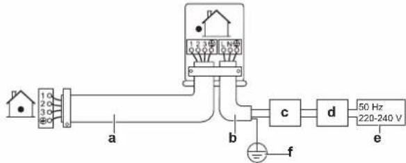
a Interconnection cable
b Power supply cable
c Circuit breaker
Earth leakage circuit breaker
e Power supply
f Earth
4 Tighten the terminal screws securely. We recommend using a Phillips screwdriver.
4.7 Finishing the outdoor unit installation
4.7.1 To finish the outdoor unit installation
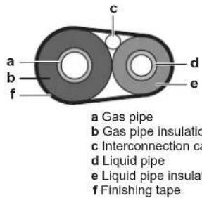
1 Insulate and fix the refrigerant piping and interconnection cable as follows:
2 Install the service cover.
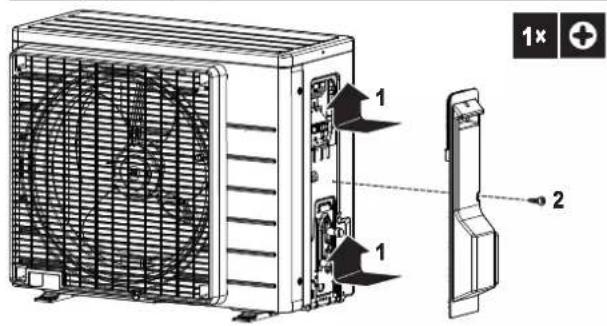
4.7.2 To close the outdoor unit

NOTICE
When closing the outdoor unit cover, make sure that the tightening torque does NOT exceed 1.3 N·m.
5 Commissioning

NOTICE
NEVER operate the unit without thermistors and/or pressure sensors/switches. Burning of the compressor might result.
5.1 Checklist before commissioning
After the installation of the unit, first check the following items. Once all below checks are fulfilled, the unit MUST be closed, ONLY then can the unit be powered up.
| □ | The indoor unit is properly mounted. |
| □ | The outdoor unit is properly mounted. |
| □ | The system is properly earthed and the earth terminals are tightened. |
| □ | The power supply voltage matches the voltage on the identification label of the unit. |
| □ | There are NO loose connections or damaged electrical components in the switch box. |
| □ | There are NO damaged components or squeezed pipes on the inside of the indoor and outdoor units. |
| □ | There are NO refrigerant leaks. |
| ☐ | The refrigerant pipes (gas and liquid) are thermally insulated. |
| ☐ | The correct pipe size is installed and the pipes are properly insulated. |
| ☐ | The stop valves (gas and liquid) on the outdoor unit are fully open. |
| ☐ | The following field wiring has been carried out according to this document and the applicable legislation between the outdoor unit and the indoor unit. |
| ☐ | DrainageMake sure drainage flows smoothly.Possible consequence: Condensate water might drip. |
| ☐ | The indoor unit receives the signals of the user interface. |
| ☐ | The specified wires are used for the interconnection cable. |
| ☐ | The fuses, circuit breakers, or locally installed protection devices are installed according to this document, and have NOT been bypassed. |
5.2 Checklist during commissioning
| □ | To perform an air purge. |
| □ | To perform a test run. |
5.3 To perform a test run
Prerequisite: Power supply MUST be in the specified range.
Prerequisite: Test run may be performed in cooling or heating mode.
Prerequisite: Test run should be performed in accordance with the operation manual of the indoor unit to make sure that all functions and parts are working properly.
1 In cooling mode, select the lowest programmable temperature. In heating mode, select the highest programmable temperature. Test run can be disabled if necessary.
2 When the test run is finished, set the temperature to a normal level. In cooling mode: 26 28^ in heating mode: 20 24^
3 The system stops operating 3 minutes after the unit is turned OFF.

INFORMATION
- Even if the unit is turned OFF, it consumes electricity.
- When the power turns back on after a power break, the previously selected mode will be resumed.
5.4 Starting up the outdoor unit
See the indoor unit installation manual for configuration and commissioning of the system.
6 Disposal

NOTICE
Do NOT try to dismantle the system yourself: dismantling of the system, treatment of the refrigerant, oil and other parts MUST comply with applicable legislation. Units MUST be treated at a specialised treatment facility for reuse, recycling and recovery.
6.1 Overview: Disposal
Typical workflow
Disposing of the system typically consists of the following stages:
1 Pumping down the system.
2 Bringing the system to a specialized treatment facility.

INFORMATION
For more details, see the service manual.
6.2 To pump down

DANGER: RISK OF EXPLOSION
Pump down - Refrigerant leakage. If you want to pump down the system, and there is a leak in the refrigerant circuit:
- Do NOT use the unit's automatic pump down function, with which you can collect all refrigerant from the system into the outdoor unit. Possible consequence: Self-combustion and explosion of the compressor because of air going into the operating compressor.
- Use a separate recovery system so that the unit's compressor does NOT have to operate.

NOTICE
During pump down operation, stop the compressor before removing the refrigerant piping. If the compressor is still running and the stop valve is open during pump down, air will be sucked into the system. Compressor breakdown or damage to the system can result due to abnormal pressure in the refrigerant cycle.
Pump down operation will extract all refrigerant from the system into the outdoor unit.
1 Remove the valve cap from the liquid stop valve and the gas stop valve.
2 Carry out forced cooling. See "6.3 To start and stop forced cooling" on page 11.
3 After 5 to 10 minutes (after only 1 or 2 minutes in case of very low ambient temperatures (< - 10^) close the liquid stop valve with a hexagonal wrench.
4 Check on the manifold if the vacuum is reached.
5 After 2-3 minutes, close the gas stop valve and stop forced cooling.
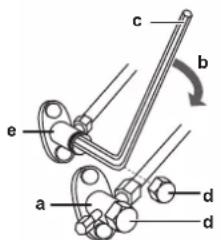
a Gas stop valve
b Closing direction
c Hexagonal wrench
d Valve cap
Liquid stop valve
6.3 To start and stop forced cooling
There are 2 methods to perform forced cooling.
- Method 1. Using the indoor unit ON/OFF switch (if present on the indoor unit).
Method 2. Using the indoor unit user interface.
6.3.1 To start/stop forced cooling using the indoor unit ON/OFF switch
1 Press the ON/OFF switch for at least 5 seconds.
Result: Operation will start.

INFORMATION
Forced cooling stops automatically after 15 minutes.
2 To stop operation sooner, press the ON/OFF switch.
6.3.2 To start/stop forced cooling using the indoor unit user interface
1 Set the operation mode to cooling.
For the procedure, refer to "To perform a test run" in the installation manual of the indoor unit.
7 Technical data
A subset of the latest technical data is available on the regional Daikin website (publicly accessible). The full set of latest technical data is available on the Daikin Business Portal (authentication required).
7.1 Wiring diagram
| Unified Wiring Diagram Legend | ||||
| For applied parts and numbering, refer to the wiring diagram on the unit. Part numbering is by Arabic numbers in ascending order for each part and is represented in the overview below by symbol ** in the part code. | ||||
| CIRCUIT BREAKER | PROTECTIVE EARTH | |||
| CONNECTION | PROTECTIVE EARTH (SCREW) | |||
| CONNECTOR | RECTIFIER | |||
| EARTH | RELAY CONNECTOR | |||
| FIELD WIRING | SHORT-CIRCUIT CONNECTOR | |||
| FUSE | TERMINAL | |||
| INDOOR UNIT | TERMINAL STRIP | |||
| OUTDOOR UNIT | WIRE CLAMP | |||
| BRN: BLACK: GRN: GREEN: PKN: PINK: WHT: WHITE | ||||
| BLU: BLUE: GRY: GREY: PRP, PPL: PURPLE: YLW: YELLOW | ||||
| ORG: ORANGE: RED: RED | ||||
| PRINTED CIRCUIT BOARD: PS: SWITCHING POWER SUPPLY | ||||
| PUSHBUTTON ON/OFF, OPERATION SWITCH: PTC: THERMISTOR PTC | ||||
| BUZZER: Q: INSULATED GATE BIPOLAR TRANSistor | ||||
| CAPACITOR: (IGBT) | ||||
| CONNECTION, CONNECTOR: Q*DI: EARTH LEAK CIRCUIT BREAKER | ||||
| Q*L: OVERLOAD PROTECTOR | ||||
| Q*M: THERMO SWITCH | ||||
| DIODE: R: RESISTOR | ||||
| DIODE BRIDGE: R*T: THERMISTOR | ||||
| DIP SWITCH: RC: RECEIVER | ||||
| HEATER: S*C: LIMIT SWITCH | ||||
| FUSE: S*L: FLOAT SWITCH | ||||
| S*NPH: PRESSURE SENSOR (HIGH) | ||||
| CONNECTOR (FRAME GROUND): PRESSURE SENSOR (LOW) | ||||
| HARNESS: PRESSURE SWITCH (HIGH) | ||||
| PILOT LAMP, LIGHT EMITTING DIODE: PRESSURE SWITCH (LOW) | ||||
| LIGHT EMITTING DIODE (SERVICE MONITOR GREEN): PRESSURE SWITCH (LOW) | ||||
| HIGH VOLTAGE: PRESSURE SENSOR: HUMIDITY SENSOR | ||||
| INTELLIGENT EYE SENSOR: OPERATION SWITCH | ||||
| INTELLIGENT POWER MODULE: SURGE ARRESTOR | ||||
| MAGNETIC RELAY: SIGNAL RECEIVER | ||||
| L: LIVE: SELECTOR SWITCH | ||||
| COIL: SHEET METAL: TERMINAL STRIP FIXED PLATE | ||||
| REACTOR: TRANSFORMER | ||||
| STEPPER MOTOR: TRANSMITTER | ||||
| COMPRESSOR MOTOR: VARISTOR | ||||
| FAN MOTOR: DIODE BRIDGE | ||||
| DRAIN PUMP MOTOR: WIRELESS REMOTE CONTROLLER | ||||
| SWING MOTOR: TERMINAL | ||||
| MAGNETIC RELAY: TERMINAL STRIP (BLOCK) | ||||
| NEUTRAL: ELECTRONIC EXPANSION VALVE COIL | ||||
| NUMBER OF PASSES THROUGH FERRITE CORE: REVERSING SOLENOID VALVE COIL | ||||
| PAM: PULSE-AMPLITUDE MODULATION: FERRITE CORE | ||||
| PCB: PRINTED CIRCUIT BOARD: NOISE FILTER | ||||
| PM: POWER MODULE: | ||||
Inhaltsverzeichnis
GEFAHR: EXPLOSIONSGEFAHR
WAARSCHUING:ONTVLAMBAAR MATERIALAAL
1.1 Pnnpopopie yia to npov Evppao 67
2 PAnpoopoe yia tn oukeuaia 68
2.1 E\xi epiikj ováδa.. 68
2.1.1 Tva aTIOUOKeuaoTe TNv EwTePikn Movda... 68
2.1.2 Tia va aqaipeTe Ta Eapntmuata aTIO TIV EeWTEpiKn 68
3 Ppoetoiia 68
3.1 Tny npoToiaoa tou xwpou Eykaradotaans 68
3.1.1 Aattnaneis 0eans Eykatataaans tns EwTepkns
ovabac . 68
3.1.2 Emiliev ataithoeic theons ykataotaans ts
EgWTEPIKns movadac o yuxpa klaipata 69
3.2 Ppoetoiiaotawovwovwovuukto 69
3.2.1 AaritnoeiGswanywwoewy uuktkou 69
3.2.2 MmKos ayoyou uukTKoKai diaopopa uouc 69
3.2.3 Movon oawvwoewy uuktkou 69
4 Eykataaotaon 70
4.1 Avorya twv povadwv 70
4.1.1 Tia va avoiEte TnV EwTepiK nuovda 70
4.2 TomoTetnon ts eEwTepiKns movdaac 70
4.2.1 Napoxn tsuTobouns ykaraataoans 70
4.2.2 EykataoTnTg Ewepikns Movadas 70
4.2.3 Paoxirarootpayyionss 70
4.2.4 Tia va atotpewete TnvaatpoTn Tns EeWTePkiNs movabac 71
4.3 Uvdoon Tuv oAnywoeW yukTKoU 71
4.3.1 2xetikαμετησυνδεοιηςωληνωngsψκικου ....71
4.3.2 Ipoopulaleis Kata n ouvdeon tsoswaiywoons uukTKoU 71
4.3.3 SuV6eON Tns OwAnVwOns yukTKoU ME TnV EeWTEpiKn ova... 71
4.4 ELeycoT wv owAnvWewv yukTKoU 71
4.4.1 Ia va eaevyEe Tia diappots 71
4.4.2 Ia va ekTeIeOeIe apuypavon kevoou 72
4.5 Pnnpwn yuktkou 72
KINADNOKINADNOSERKAYMATO
Suvnncsdiakaa-HIAPOWENETITPPOOeTOU yukTKOU uVHwC TEPIAaBavei ta akolouo aTadia:
1 Tov poooioipoiou tro avaykns eTTIPOoOeTng TAnpwoanKai Tns aattouoevnc TIOoTntac.
2 Eav aataiteiai, Tny TAnpwn 8Tinppo8eou yuktkou.
3 Tn ouptanpwon ts EIKETACg Oepiouxwv aeipwEepokntiou kai tvtoTTOHTON ts 0To eWTEPIKO TS EwTEPIKns Movadac.
IIIpnS ETTAVATANPwn yukTKOU
IpoTu PPOxPnOeTe Oe TAnpN EtTavatAnpwn YUKTKoU, a i w i e 0f exouy yivei Ta Ens
1 Suvoiak avaktnon yuktkou aTo to ouotma.
2 OTI EXTE EAEYEI TIV EWTEPIKN OAWHwON YUKTKOU TNS EWTEPIKN ovaOAC (DOKUN diappoNc, apuypavon Kevou).
3 OTI EXYE EKTELEEi apuypavon KEVO OTNV EOWTEPIKN OAWNVON YUKTIKOU TNS EWEPTIKN Movadac.

EIDONOIHEH
Pniv ato Tny nnn enn aan npwn, kteleote etllons oteywma eekewon otis oowepikcs oawvwoies uuktkou ts es wotepikns movabac.
Suvnqns biadikaoia-H nnpns tavaanpwn yuktkou ouvno Tepiaaabe ta akoloutheta tdia:
1 Tov npoodiopio nT aataouevns nootntas npwons.
2 TnyTnnpwn yuktikou
3 Tn ouptanpwn ts EIKETACg Ptoipouxwv aeipwEepokntiou KAI TIV TOIOETNOI TS OTO EOWTEPIKO TS EWSTEPIKns Movadac.
4.5.5 Ia npwn EITnpoOeTOU yukTKOU

NPOEIADONIOIHEN
XpnaiuioTIOIEAtTOkAeiTikR32ωS yuktiKo μeoo. Aaaa uika evexetai va Tpokaéouv ekpneic n aaaa atuxjmuata.
To R32 TEPiExei OTOIOUXa aepia 0epuokntiou.To GWP (duvauiko TIAvNTIKU UTEpEepavon) tou evai 675.MHN atTAEUVEPWVE Ta aepia auta otnv atmuopqipaa.
- Otav paymuToIOeIe Tnpwn yukTko, opate NANTA Tpootatuikya vvtia kai yuaia aopaaleiac.
PouT6eO: PIV aTO TnV TAnpwn yukTKoU, BepaiWteIe oTH ExETe Ouvoei KAI ELeyEi Tn OwAnvwn yukTKoU (Dokiun diappOns KAI apuypavon kevo).
1 SuVbEOTe Tov KauivDpo yuktiKou oTn UupiDa uvtnpnOc.
2 PAnpOte μe TnV TnpOoθεTn TooOToTα uKtikou.
3 AvoiETe Tn diakottns aepiou.
4.5.6 Ia va koAaIooTe TnV TOnuYawOoN ETIKeTa Yia Ta OOpIoUxa aepia o iou
4.2 MoHTax HApyXHOro arperaTa [91]
3.2Под�отовkaТрубонровoda xнадаrenta
3.2.1 Tpe6oBaHnK Tpy6oNpOBoDam XnaDarEHTa
-MatepnaHn3rOToBneHn Tpy6:BecuOBHaMeB, NODBepHyTayΦocΦopHOKNCJOn aHTNOKNCInTeNbHO 6pb6oTKe.
-ДиametTppy6ok:
4.2 MoHTaX HApyXHoro arperata
4.2.1 NpOroTOBka MOHTaXHOH KOHCTpyKUIM
IIOIROTOBbTe 4 KOMNKeT aHKePbIX 6oITOB M8 nM M10 c raikamn uan6aamn (npno6peTaETcNo MeCTy yCTaHOBKn).
B JIO6OM cIyue ae NOI 6NOKOM DOJNXHO OCTaBaTbC Hr MeHee 300 MM CBO6oHOrO NPOCTpaHCTBa. Kpome TOrO, Heo6xOdImo npocneiHTb 3a TEM, YTO6bl 6NOK HaxOuINcR, KaK MHNIMyM, B 100 MM NaI paCteTHOI NOBepXHOCTbO CHEKHO rOKPOBa. IInr 3TOrO peKOMEHdyETcYCTaHOBnTB 6NOK Ha NoCTaBky.
4.2.2 YctaHOBka HapyxHoro 6Joka
4.2.3 06ycTpoIcTBo IpeHaxa

PIMMEUAHNE
Ecnn 6nK 3KcNlnyaTnpyetc B yCIOBnx XoIOnHO KIMMaTa, Heo6xOIMo npHnTb MepBo IV3EKEKAHNE 3aMep3aHnO kAuaBaemoro KOHehCata.

HHOPMALI
No noBdy INΦopMaζιn o DocTyHbIX onζηx σβpaTntecb K CBOeMy DInepy.

ПРИМЕЧАNH
OeBte 3aOp nOd 6nOKm He MeHee 300 MM. Kpome TOrO, y6eNTecb B Tom, qTO 6nOK pacnoJoxen KaM Hmym Ha 100 MM Bblpe npednonaraemOn NOBepxHOCTn CHEKHO TOKPOBA.
1IcnoJb3yIte cInBHyIO np6ky.
2 NcnoB3yIe 1nHaH 016 MM (npno6peTaetc no Mecty yCTaHOBKn).
a CnBHOE OTBEPCTNE
b HxHpa
cCInBnA npo6ka
d WJnahr (npno6peTaetcNo MeCtTy yCTaHOBKn)
4.2.4 Yto6bI n36exaTb onpOKnDbIBaHn HapyXHoro arperata
B cnyae yctahOBKn 6Ioka B MeCTax, Ie CnIbHbI Betep MoKet ero HAKNOHTb, Heo6xOdmo npInrTa CneDyUOune Mebl:
1NoIroToBbTe 2 Ka6eNa, KaN oKa3aHo Ha cNeDyHoue nnIOCTpaunn (npno6peTaIOTcNO MeCy yCTaHOBKn).
2 NpOJKeTc 2 Ka6eIa Ha HApyKbHb 6nok.
3YtO6bI Ka6eH He noUapanAn Kpacky, ynoKInTe MeKdy Ka6eJMaH HApXhBIM 6nOKom JnCT pe3HHbI (npno6peTaETcNo MeCy ycTaHOBKn).
4 NodcoeHNHTe 3akpennte KOHcI Ka6ene.
4.3 CoeHHeHne Tpy6 Tpy6onpoBoda xJaDaReHTa

ONACHOI PNCK OXOTOB
Pnctyna K nooCoeHHeHIO Tpy60npOBoOxJaDaTeHa
Y6eINTEcB TOM, YTO yCTaHObKa HApXHOrO IN BHyTpEHHIX 6NOKOB BbINOJIHeHa NOLHOCTbIO.
TnOBa nocJeDoBaTeNbHOCtB DeCTBn
IpoedoeHHeHne Tpy6oNpOBoDOb XnaadareHTa npEpyCmTaPnBaET:
- CoeHHeHHe Tpy6oNpOBoDxnaDaReHtacBHyTpEHHM 6JIOKOM
-
CoeHHHeHn Tpy60npoBOoB XnaIaReHTa C HApyKbIM 6NOKOM
-ИэляинуТурбоноВовхладагентА
Co6JIOdaTe yka3aHnno BbINOHNHeHnO cneyUoX np60T -
U3n6aHne Tpy6
Pa3BaJIbOBAKa KOHcOB Tpy6
-ПимененезаорьхкпаанOB
4.3.2 MepbI npedocTopoxHoctn npn noDcoeHNHeHn Tpy6oNpOBOOB xnaaareHTa

ONACHO!PNCOKXKOTOB

IPEINOCTEPEXEHNE
-Испόньзуге зakpenленин hyо Ha rnaBHom 6noke HauNDHyU raNky.
- YTo6bI npEDoTbPaTnTb yTeKy r3a, HAnecite PheOHOBoE MaCNo TOnbKO Ha BHyTpEHHIO NOBepxHOCbTb pacTy6a. NcNtB3yTe PheOHOBoE MaCNo, NpEHa3NaueHHeO dnn XnaDaareHTa R32.
3AIPPEUJAETCNOBTOHoeNcnoJIb3OBAHne Tpy6hbx COeINHeHn.

IPEyIPEKDEHNE
ObecneYte HaedXHocTb coeHHeHH TpybOpBoDa xHaadaReHTa, npKxJyem 3anyckaTb KOMPpeccop. Ecnn Bo BpEma pa6Obl KOMPecCopa TpybOpBODb XHaadaReHTa HE 3akpenHeB, a3anOpHbN BeHTnB OTKpbIT, TO BCacBaHHe BO3dyxa PnBODNT K OKKnHOHeHH DaBHeHH B KOHType XHaadaReHTa OT HopMbI, YTO QPeBaTO NobpeXdHHeM O6OpDoBaHH N daXe HaHeceHEm TpaBMl.
4.3.3ПодсоeнHeHne Tpy6oNpOBoDa xnaDarEHTa K HapyXHomy 6noky
-Динна trpy6onpoBOOB.Tpy6onpoBOBno MeCTy MOHTaKa DOJKNHb 6bITb KAK MOXHO KOPOye.
3aunTa Tpy6oNpOBOOB.Heo6xOJIMO o6ecneHTb 3aunTy Tpy6oNpOBOOB NO MecTy MOHTaxa OT fHn3uYeCKORO nOBpeXJeHna.
1 CoeINHnTe NaIpybok KxNkORo XnaJaAReHTa BHyTpeHrero 6Noka C KxNkOcTHbIM 3aOpHbIM BeHTnJIem HApyKHOro 6Noka.
a3aOpHbIeBHTINbKoHTypeXIAIDKORXnAJaareHteT a3aOpHbIeBHTINbra3OBJIOJIHHN
C CepBnCHOe OTBepCTne
2 CoeHHnTe naTpy6ok ra30o6pa3Horo xnaIaReHTa BHyTpHeHero 6noka c 3anOpHbIM BeHTnJIem ra30o6pa3Horo xnaIaReHTa HapyXHO rO 6noka.

PIMMEUHNE
PekomeHydetyc npoknabibatb ty60npoBxnaaReHTa MeJy BHTpeHHIM HapyHbIM arperaTOM B BO3dyXOBode N6o 6opapuBaTb erO hapyKHO6MOtKoI.
4.4 Праверka Трубовозахладагента
4.4.1 IpoBepka Ha yTeKn

ПРИМЕЧАНЕ
HE npBbIaIe MaKcImaJIbHoe pa6Ooee daBJIeHne 6noka (CM. napaMeTp PS High ha nacnopTHoi Ta6nUyKe 6noka).

ПРИМЕЧАНЕ
O63aTeBHO nCnONb3yIte pactBOp dIra npoBeDeHn npobHa o6pa3OBaHne ny3bIpei, peKOMeHDoBaHHbI Bauim NoCTabuNkOM. He nCNoJIb3yIte MbInbHbI BODaHOn pactBOP, KOToPbIM MOKeT Bbl3BaTb pAcTpeCKINBAHHe HAKINbIX Taek (B MbJbHOM BOdHOM pACTBoMeOKeT coPeKxTaCBc CoIb, KOTopar BNITbIaET BnABy, 3aMep3aUyIo npri OXnaJdeHN TpyBonpoBOOB) N pInBecNT K Kopp03N KOHuecknx CoEINHeHn (B MbJbHOM BoaHOM pactBoTe MOKeT coPeKxTaCBc AAMNAK, KOToPb I BbIOBt KoppoHOHHbI 3ΦΦeKt MExdy NaTyHHo HAKINHO rAIKO IN MeDhbIM pactpy6om).
13anpaBte cntemy a30tOM do daBHeHnHa He MeHee 200 KPa (26ap). DnB BbIaBHeHn H3NaHTeNbHbIX yTeek peKoMeHdyetc DOBeCTn daBHeHne Do 3000 KPa (306ap).
2 PpOBepe Te CnCTeMy Ha repMeTuHOCtB, HAnecr pAcTbOp DnI npOBeHeHn Ipo6bHa O6pa3oBaHne Npy3bipeH Ha BCE Tpy6HbIe COeINHeHn.
3 BbInyctnte Becb a3oT.
4.4.2 IpoBeHne BaKyHMoH cyuKn
1 Bakuympyte cnTeMy do Tex nop, noka daBneHne B konnektope he coctabnt-0,1 MNa (-16ap).
2OCTaBnB CNTEmy B NOKoe Ha 4-5 MNHyT, npOBepbTe daBneHHe: