
One+ RPLS18X - Saw RYOBI - Free user manual and instructions
Find the device manual for free One+ RPLS18X RYOBI in PDF.

| Product Type | Cordless plunge saw |
| Brand | RYOBI |
| Model | One+ RPLS18X |
| Power Source | 18 V lithium-ion battery (One+ system) |
| Max Cutting Depth | 54 mm |
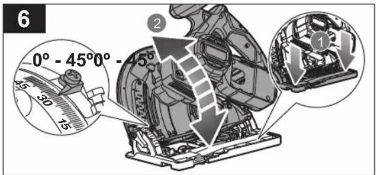
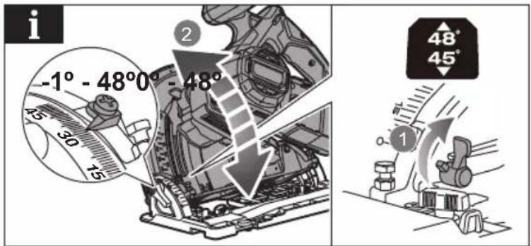
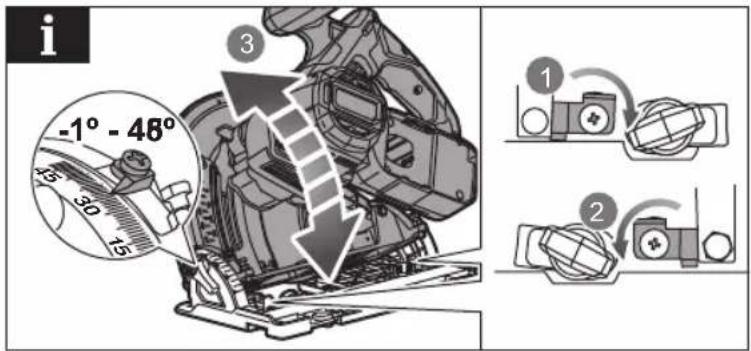
| Bevel Cut Angle | -1° to 48° |
| Blade Diameter | 165 mm (approx) |
| Weight | Approximately 4.5 kg (approx) |
| Intended Use | Crosscutting and ripping of wood and similar materials (not metal) |
| Guidance System | Compatible guide rail (supplied) |
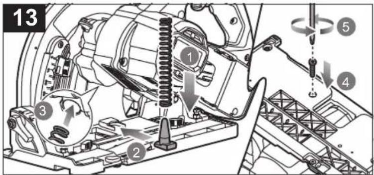
| Blade Guard | Pivoting blade guard with return spring |
| Riving Knife | Yes, removable for plunge cuts |
| Safety Features | Trigger lock, spindle lock button, insulated gripping surfaces |
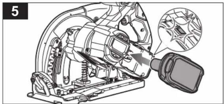
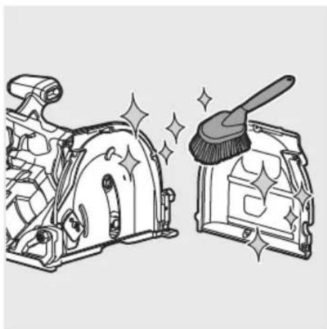
| Maintenance | Clean with a dry cloth; do not use solvents |
| Spare Parts and Repairability | Use only genuine parts; repair by an authorized service center |
| Operating Temperature | 0 °C to 40 °C |
| Storage Temperature | 0 °C to 40 °C |
| Warranty | 24 months, extendable via online registration |
| Required Protective Equipment | Wear eye protection, hearing protection, and dust mask |
| Safety Symbols | Read manual, hearing/eye protection/mask, recycling |
Frequently Asked Questions - One+ RPLS18X RYOBI
User questions about One+ RPLS18X RYOBI
0 question about this device. Answer the ones you know or ask your own.
Ask a new question about this device
Download the instructions for your Saw in PDF format for free! Find your manual One+ RPLS18X - RYOBI and take your electronic device back in hand. On this page are published all the documents necessary for the use of your device. One+ RPLS18X by RYOBI.
USER MANUAL One+ RPLS18X RYOBI
natural_image
Close-up of a YOBI cutting machine with a metal bracket, set against a striped background (no visible text or symbols)
natural_image
Exterior view of a Ryobi One 8 HP industrial saw blade (no signage or text beyond branding)
natural_image
Close-up of a textured surface with diagonal hatching and a horizontal gray bar at the bottom (no text or symbols)EN FR DE ES IT NL PT DA SV FI NO RU PL CS HU RO LV LT ET HR SL SK BG UK TR EL
RPLS18X

Important! It is essential that you read the instructions in this manual before assembling, maintaining and operating the product.
Safety, performance, and dependability have been given top priority in the design of your plunge saw.
INTENDED USE
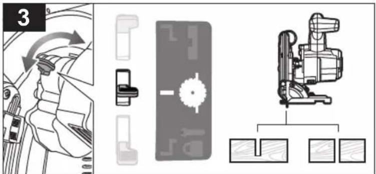
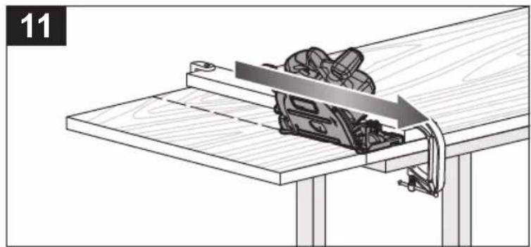
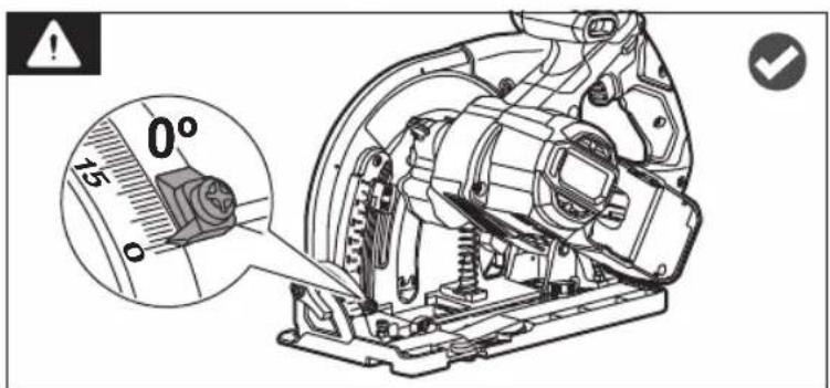
The plunge saw is designed for rip- and cross-cutting of wood or similar materials up to a maximum depth of 54 mm. The product can make straight or bevelled cuts between -1 and 48 degrees.
GENERAL POWER TOOL SAFETY WARNINGS
⚠ WARNING! Read all safety warnings, instructions, illustrations and specifications provided with this power tool. Failure to follow all instructions listed below may result in electric shock, fi re and/or serious injury.
Save all warnings and instructions for future reference. The term "power tool" in the warnings refers to your mains-operated (corded) power tool or battery-operated (cordless) power tool.
WORK AREA SAFETY
- Keep work area clean and well lit. Cluttered or dark areas invite accidents.
- Do not operate power tools in explosive atmospheres, such as in the presence of flammable liquids, gases or dust. Power tools create sparks which may ignite the dust or fumes.
- Keep children and bystanders away while operating a power tool. Distractions can cause you to lose control.
ELECTRICAL SAFETY
■ Power tool plugs must match the outlet. Never modify the plug in any way. Do not use any adapter plugs with earthed (grounded) power tools. Unmodified plugs and matching outlets will reduce risk of electric shock.
- Avoid body contact with earthed or grounded surfaces, such as pipes, radiators, ranges and refrigerators. There is an increased risk of electric shock if your body is earthed or grounded.
- Do not expose power tools to rain or wet conditions. Water entering a power tool will increase the risk of electric shock.
- Do not abuse the cord. Never use the cord for carrying, pulling or unplugging the power tool. Keep cord away from heat, oil, sharp edges or moving parts. Damaged or entangled cords increase the risk of electric shock.
- When operating a power tool outdoors, use an extension cord suitable for outdoor use. Use of a cord suitable for outdoor use reduces the risk of electric shock.
If operating a power tool in a damp location is unavoidable, use a residual current device (RCD) protected supply. Use of an RCD reduces the risk of electric shock.
PERSONAL SAFETY
- Stay alert, watch what you are doing and use common sense when operating a power tool. Do not use a power tool while you are tired or under the influence of drugs, alcohol or medication. A moment of inattention while operating power tools may result in serious personal injury.
■ Use personal protective equipment. Always wear eye protection. Protective equipment such as a dust mask, non-skid safety shoes, hard hat, or hearing protection used for appropriate conditions will reduce personal injuries.
■ Prevent unintentional starting. Ensure the switch is in the off -position before connecting to power source and/or battery pack, picking up or carrying the tool. Carrying power tools with your finger on the switch or energising power tools that have the switch on invites accidents.
■ Remove any adjusting key or wrench before turning the power tool on. A wrench or a key left attached to a rotating part of the power tool may result in personal injury.
- Do not overreach. Keep proper footing and balance at all times. This enables better control of the power tool in unexpected situations.
■ Dress properly. Do not wear loose clothing or jewellery. Keep your hair and clothing away from moving parts. Loose clothes, jewellery or long hair can be caught in moving parts.
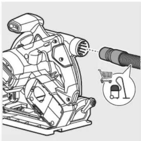
If devices are provided for the connection of dust extraction and collection facilities, ensure these are connected and properly used. Use of dust collection can reduce dust-related hazards.
- Do not let familiarity gained from frequent use of tools allow you to become complacent and ignore tool safety principles. A careless action can cause severe injury within a fraction of a second.
POWER TOOL USE AND CARE
- Do not force the power tool. Use the correct power tool for your application. The correct power tool will do the job better and safer at the rate for which it was designed.
- Do not use the power tool if the switch does not turn it on and off. Any power tool that cannot be controlled with the switch is dangerous and must be repaired.
■ Disconnect the plug from the power source and/or remove the battery pack, if detachable, from the power tool before making any adjustments, changing accessories, or storing power tools. Such preventive safety measures reduce the risk of starting the power tool accidentally.
■ Store idle power tools out of the reach of children and do not allow persons unfamiliar with the power tool or these instructions to operate the power tool. Power tools are dangerous in the hands of untrained users. - Maintain power tools and accessories. Check for misalignment or binding of moving parts, breakage of parts and any other condition that may affect the power tool's operation. If damaged, have the power tool repaired before use. Many accidents are caused by poorly maintained power tools.
- Keep cutting tools sharp and clean. Properly maintained cutting tools with sharp cutting edges are less likely to bind and are easier to control.
- Use the power tool, accessories and tool bits etc. in accordance with these instructions, taking into account the working conditions and the work to be performed. Use of the power tool for operations different from those intended could result in a hazardous situation.
- Keep handles and grasping surfaces dry, clean and free from oil and grease. Slippery handles and grasping surfaces do not allow for safe handling and control of the tool in unexpected situations.
BATTERY TOOL USE AND CARE
■ Recharge only with the charger specified by the manufacturer. A charger that is suitable for one type of battery pack may create a risk of fire when used with another battery pack.
■ Use power tools only with specifically designated battery packs. Use of any other battery packs may create a risk of injury and fire.
- When battery pack is not in use, keep it away from other metal objects, like paper clips, coins, keys, nails, screws or other small metal objects, that can make a connection from one terminal to another. Shorting the battery terminals together may cause burns or a fire.
■ Under abusive conditions, liquid may be ejected from the battery; avoid contact. If contact accidentally occurs, flush with water. If liquid contacts eyes, additionally seek medical help. Liquid ejected from the battery may cause irritation or burns.
- Do not use a battery pack or tool that is damaged or modified. Damaged or modified batteries may exhibit unpredictable behaviour resulting in fire, explosion or risk of injury.
- Do not expose a battery pack or tool to fire or excessive temperature. Exposure to fire or temperature above 130°C may cause explosion.
■ Follow all charging instructions and do not charge the battery pack or tool outside the temperature range specified in the instructions. Charging improperly or at temperatures outside the specified range may damage the battery and increase the risk of fire.
SERVICE
■ Have your power tool serviced by a qualified repair person using only identical replacement parts. This will ensure that the safety of the power tool is maintained.
■ Never service damaged battery packs. Service of battery packs should only be performed by the manufacturer or authorized service providers.
SAFETY INSTRUCTIONS FOR PLUNGE SAW
CUTTING PROCEDURES
- DANGER: Keep hands away from cutting area and the blade. Keep your second hand on auxiliary handle, or motor housing. If both hands are holding the saw, they cannot be cut by the blade.
- Do not reach underneath the workpiece. The guard cannot protect you from the blade below the workpiece.
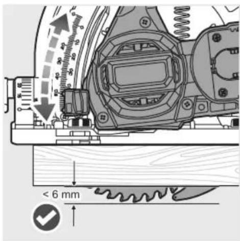
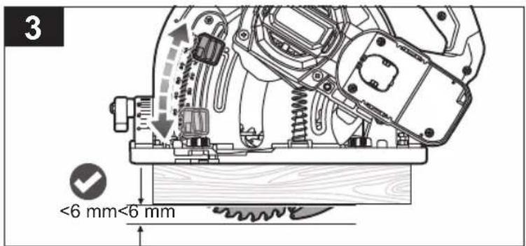
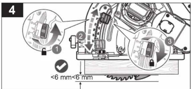
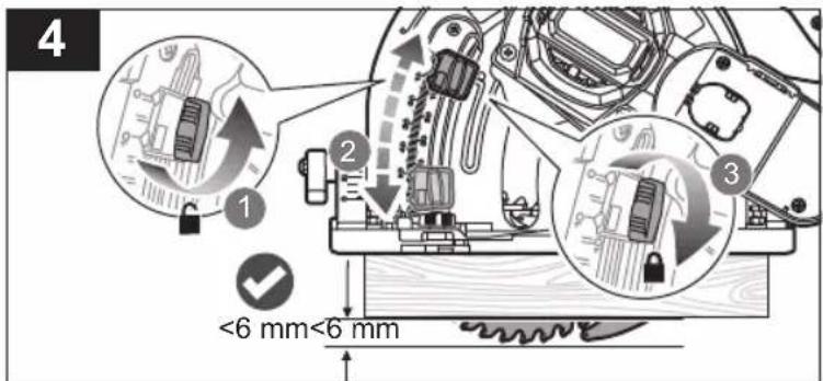
- Adjust the cutting depth to the thickness of the workpiece. Less than a full tooth of the blade teeth should be visible below the workpiece.
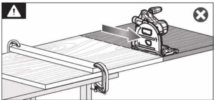
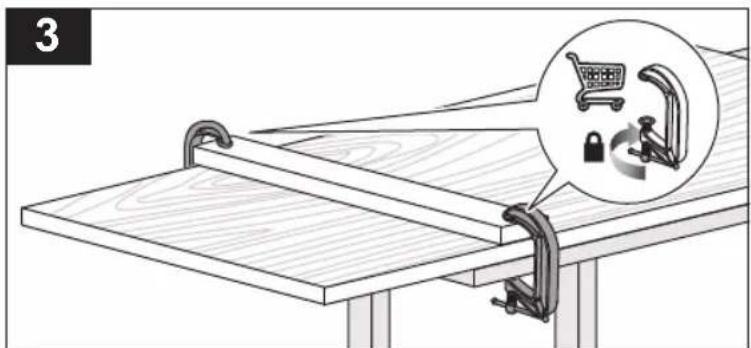
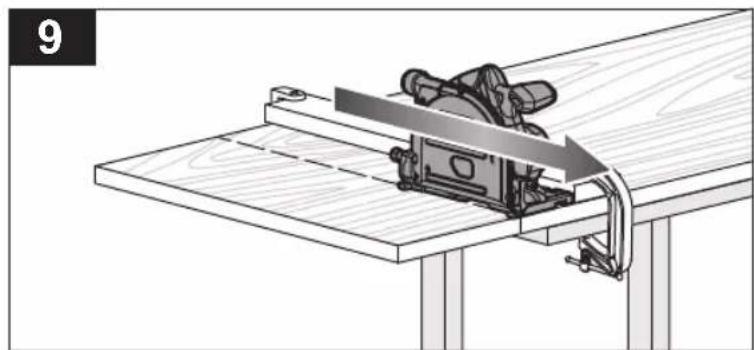
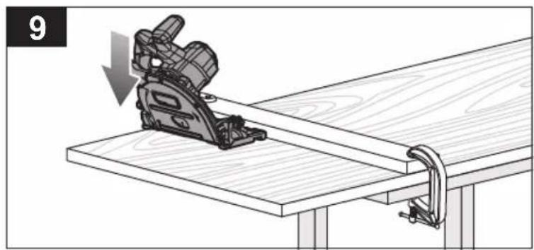
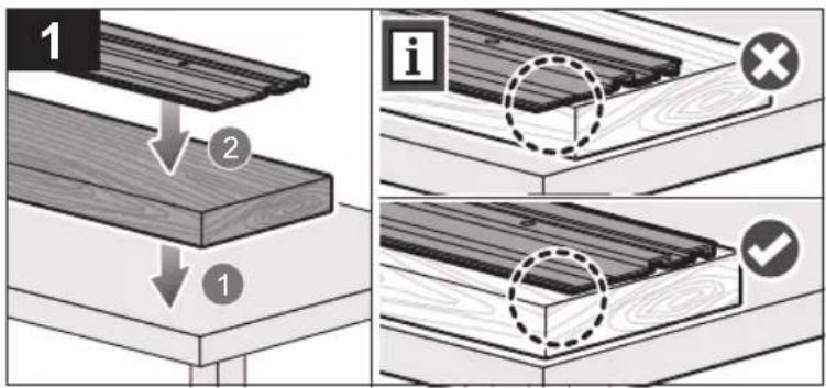
■ Never hold the workpiece in your hands or across your leg while cutting. Secure the workpiece to a stable platform. It is important to support the work properly to minimize body exposure, blade binding, or loss of control.
■ Hold the power tool by insulated gripping surfaces, when performing an operation where the cutting tool
may contact hidden wiring. Contact with a "live" wire will also make exposed metal parts of the power tool "live" and could give the operator an electric shock.
- When ripping, always use a rip fence or straight edge guide. This improves the accuracy of cut and reduces the chance of blade binding.
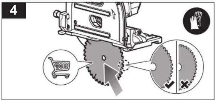
■ Always use blades with correct size and shape (diamond versus round) of arbour holes. Blades that do not match the mounting hardware of the saw will run eccentrically, causing loss of control.
■ Never use damaged or incorrect blade washers or bolt. The blade washers and bolt were specially designed for your saw, for optimum performance and safety of operation.
KICKBACK CAUSES AND RELATED WARNINGS:
■ kickback is a sudden reaction to a pinched, jammed or misaligned saw blade, causing an uncontrolled saw to lift up and out of the workpiece toward the operator;
■ when the blade is pinched or jammed tightly by the kerf closing down, the blade stalls and the motor reaction drives the unit rapidly back toward the operator;
■ if the blade becomes twisted or misaligned in the cut, the teeth at the back edge of the blade can dig into the top surface of the wood causing the blade to climb out of the kerf and jump back toward the operator.
Kickback is the result of saw misuse and/or incorrect operating procedures or conditions and can be avoided by taking proper precautions as given below.
- Maintain a firm grip with both hands on the saw and position your arms to resist kickback forces. Position your body to either side of the blade, but not in line with the blade. Kickback could cause the saw to jump backwards, but kickback forces can be controlled by the operator, if proper precautions are taken.
- When blade is binding, or when interrupting a cut for any reason, release the trigger and hold the saw motionless in the material until the blade comes to a complete stop. Never attempt to remove the saw from the work or pull the saw backward while the blade is in motion or kickback may occur. Investigate and take corrective actions to eliminate the cause of blade binding.
- When restarting a saw in the workpiece, centre the saw blade in the kerf so that the saw teeth are not engaged into the material. If saw blade binds, it may walk up or kickback from the workpiece as the saw is restarted.
■ Support large panels to minimise the risk of blade pinching and kickback. Large panels tend to sag under their own weight. Supports must be placed under the panel on both sides, near the line of cut and near the edge of the panel. - Do not use dull or damaged blades. Unsharpened or improperly set blades produce narrow kerf causing excessive friction, blade binding and kickback.
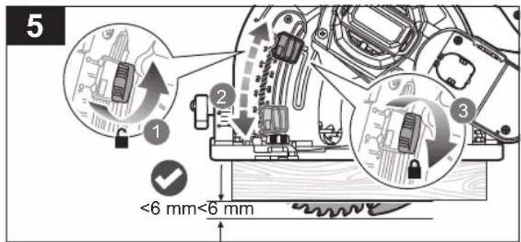
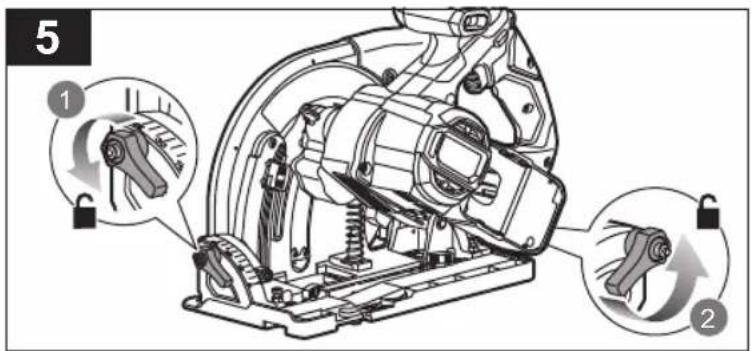
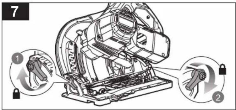
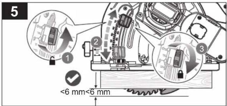
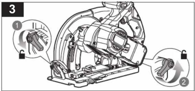
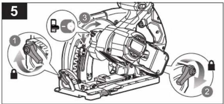
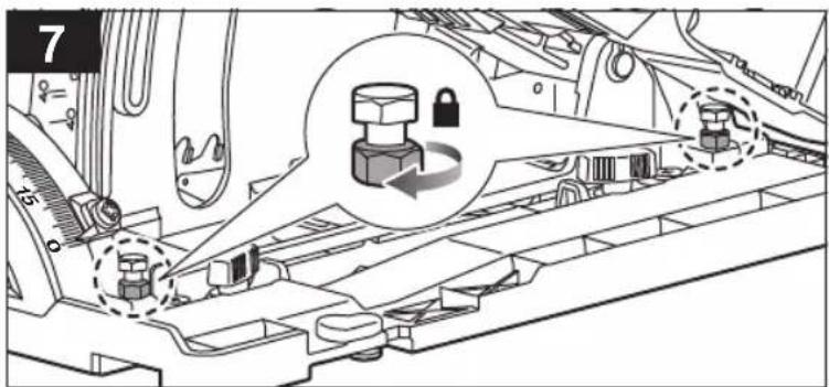
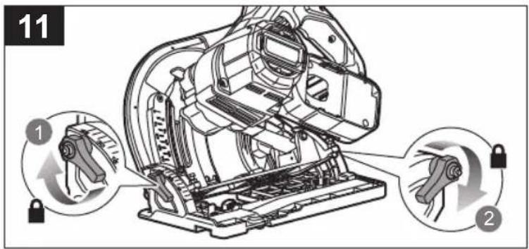
■ Blade depth and bevel adjusting locking levers must be tight and secure before making cut. If blade adjustment shifts while cutting, it may cause binding and kickback.
■ Use extra caution when sawing into existing walls or other blind areas. The protruding blade may cut objects that can cause kickback.
GUARD FUNCTION
- Check the guard for proper closing before each use. Do not operate the saw if guard does not move freely and enclose the blade instantly. Never clamp or tie the guard so that the blade is exposed. If saw is accidentally dropped, guard may be bent. Check to make sure that guard moves freely and does not touch the blade or any other part, in all angles and depths of cut.
- Check the operation and condition of the guard return spring. If the guard and the spring are not operating properly, they must be serviced before use. Guard may operate sluggishly due to damaged parts, gummy deposits, or a build-up of debris.
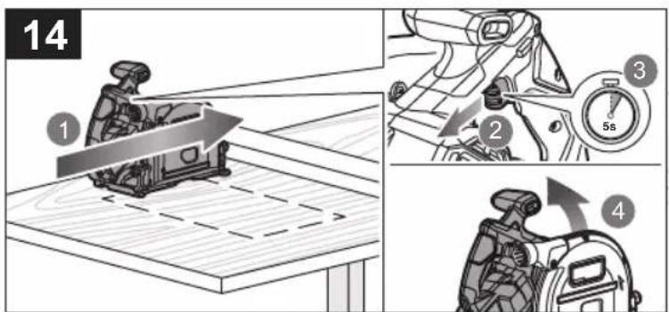
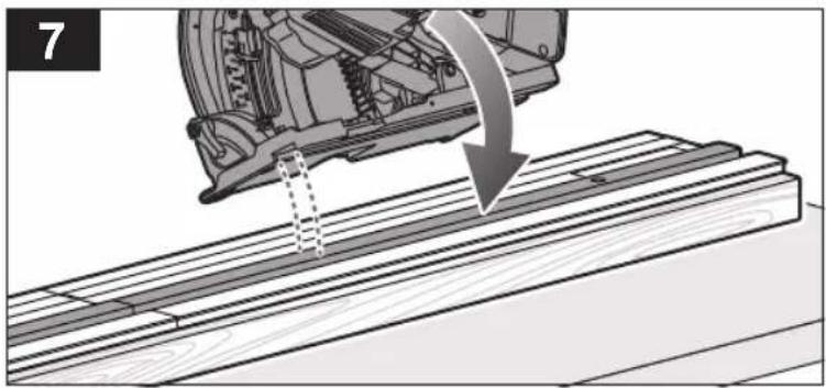
- Assure that the base plate of the saw will not shift while performing the “plunge cut”. Blade shifting sideways will cause binding and likely kick back.
■ Always observe that the guard is covering the blade before placing saw down on bench or floor. An unprotected, coasting blade will cause the saw to walk backwards, cutting whatever is in its path. Be aware of the time it takes for the blade to stop after switch is released.
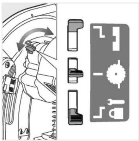
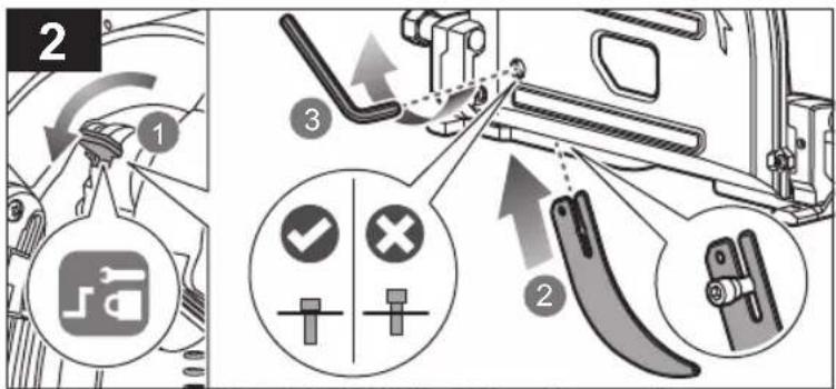
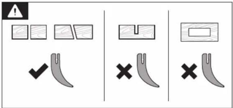
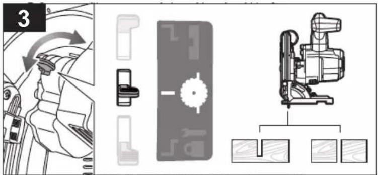
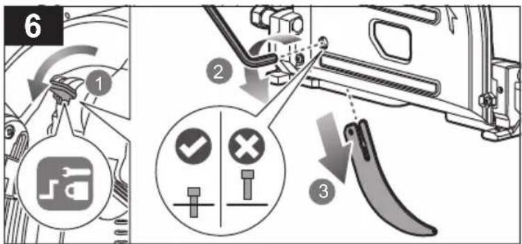
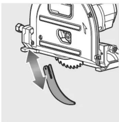
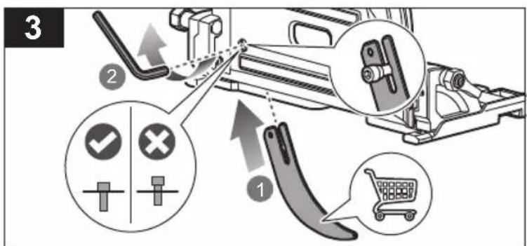
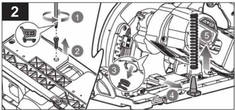
RIVING KNIFE FUNCTION
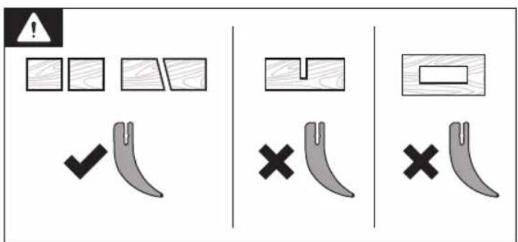
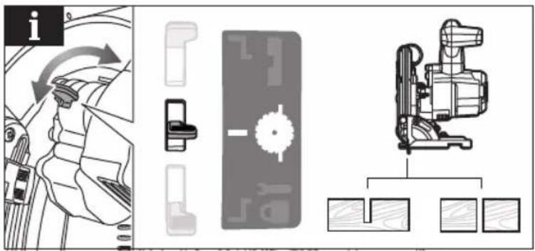
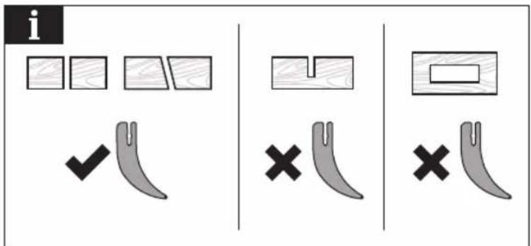
■ Use the appropriate saw blade for the riving knife. For the riving knife to function, the body of the blade must be thinner than the riving knife and the cutting width of the blade must be wider than the thickness of the riving knife.
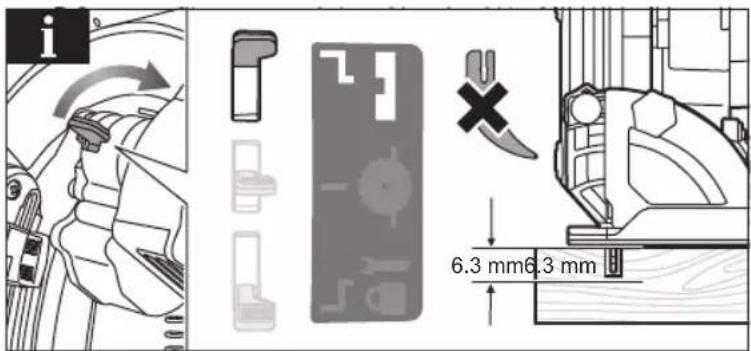
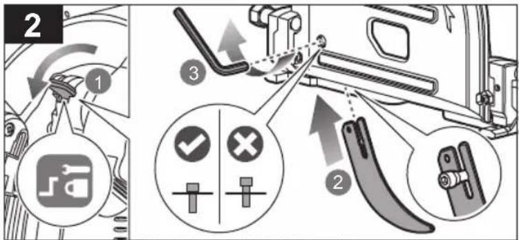
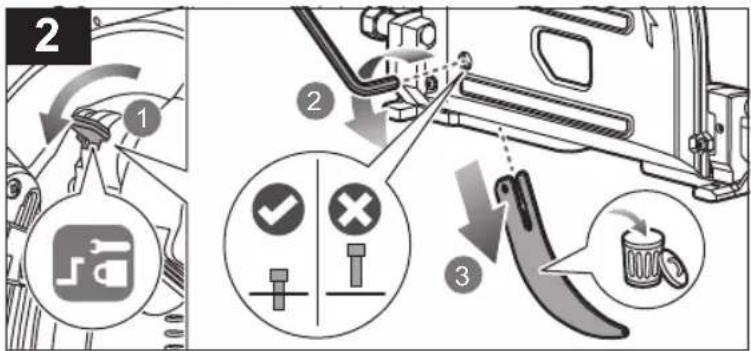
- Adjust the Riving knife as described in this instruction manual. Incorrect spacing, positioning and alignment can make the riving knife ineffective in preventing kickback.
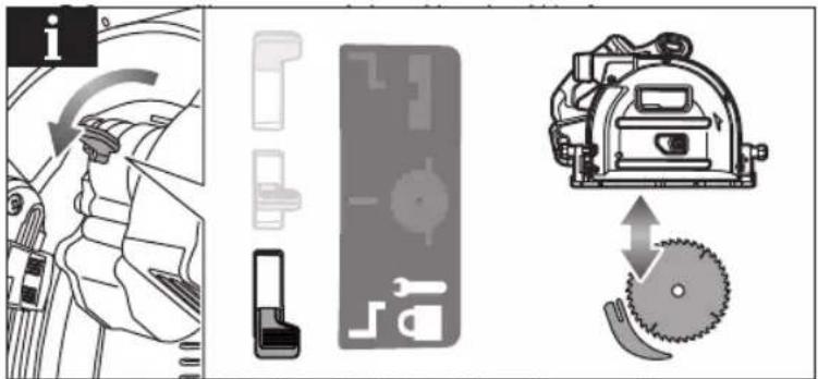
■ Always use the riving knife except when plunge cutting. The riving knife must be replaced after plunge cutting. The riving knife causes interference during plunge cutting and can create kickback.
For the riving knife to work, it must be engaged in the workpiece. The riving knife is ineffective in preventing kickback during short cuts.
- Do not operate the saw if the riving knife is bent. Even a light interference can slow the closing rate of a guard.
ADDITIONAL SAFETY WARNINGS
■ Do not use any abrasive wheels.
■ Use only blade diameter(s) in accordance with the markings.
■ Identify the correct saw blade to be used for the material to be cut.
■ Use only saw blades that are marked with a speed equal or higher than the speed marked on the tool.
■ Use only saw blades recommended by the manufacturer, which conform to EN 847-1, if intended for wood and analogous materials.
■ Wear a dust mask.
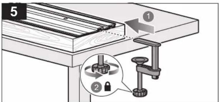
- Clamp workpiece with a clamping device. Unclamped workpieces can cause severe injury and damage.
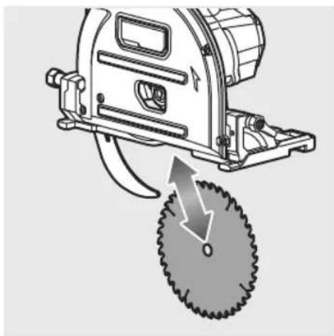
- Check and make sure that the blade guard functions properly. Follow the steps below to check the proper function of the blade guard.
- Ensure that the battery is removed from the product.
-
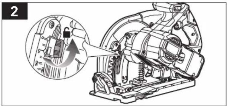
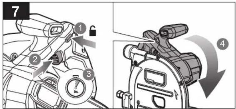
Press the lock-off button.
-
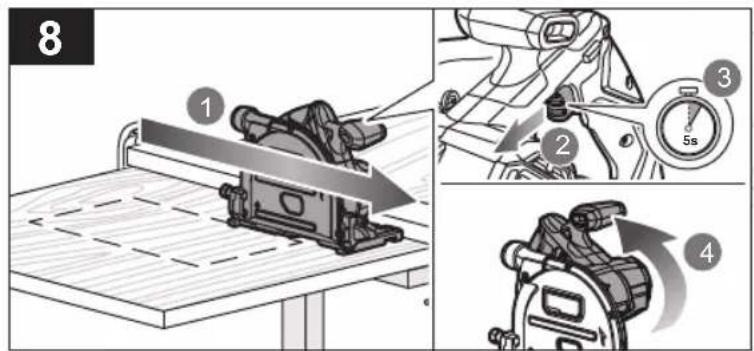
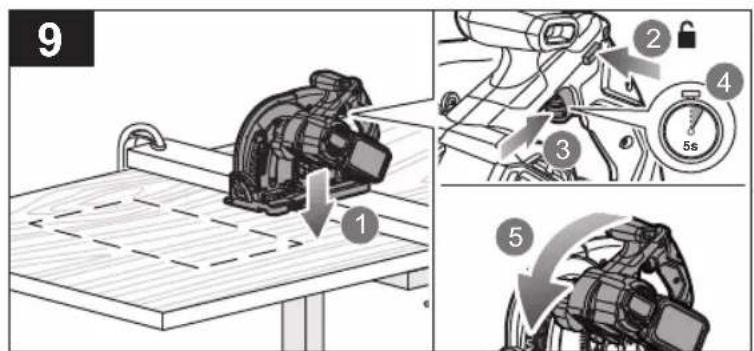
Grasp the front handle and apply downward pressure to lower and expose the blade.
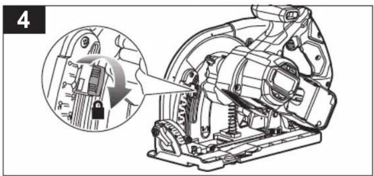
- Slowly allow the front handle to rise until the blade is completely inside of the guard.
- Make sure that the blade guard fully encloses the blade.
- If the guard and the spring are not operating properly, they must be serviced before use.
Injuries may be caused, or aggravated, by prolonged use of a tool. When using any tool for prolonged periods, ensure you take regular breaks.
- Do not switch on the product again after it has stalled. Switching it on again can cause a kickback with high reaction force. Determine why the product has stalled and rectify it, paying heed to the safety instructions.
■ Ambient temperature range for tool during operation is between 0°C and 40°C.
■ Ambient temperature range for tool storage is between 0°C and 40°C.
■ The recommended ambient temperature range for the charging system during charging is between 10°C and 38°C.
ADDITIONAL BATTERY SAFETY WARNINGS
■ To reduce the risk of fire, personal injury, and product damage due to a short circuit, never immerse your tool, battery pack or charger in fluid or allow a fluid to flow inside them. Corrosive or conductive fluids, such as seawater, certain industrial chemicals, and bleach or bleach-containing products, etc., can cause a short circuit.
■ Ambient temperature range for battery during use is between 0 °C and 40 °C.
■ Ambient temperature range for battery storage is between 0 °C and 20°C.
TRANSPORTING LITHIUM BATTERIES
Transport the battery in accordance with local and national provisions and regulations.
Follow all special requirements on packaging and labelling when transporting batteries by a third party. Ensure that no batteries can come in contact with other batteries or conductive materials while in transport by protecting exposed connectors with insulating, non-conductive caps or tape. Do not transport batteries that are cracked or leaking. Check with the forwarding company for further advice.
KNOW YOUR PRODUCT
See page 134.
- Front handle, insulated gripping surface
- Lock-off button
- Switch trigger
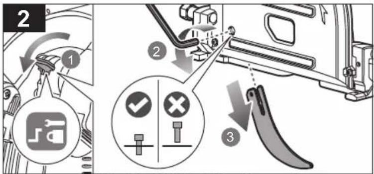
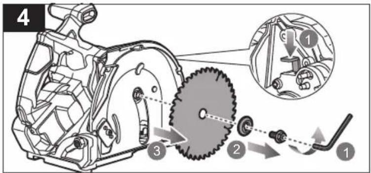
- Spindle lock
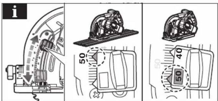
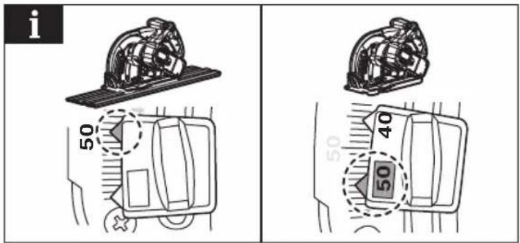
- Depth control lever
- Handle, insulated gripping surface
- Depth of cut indicator
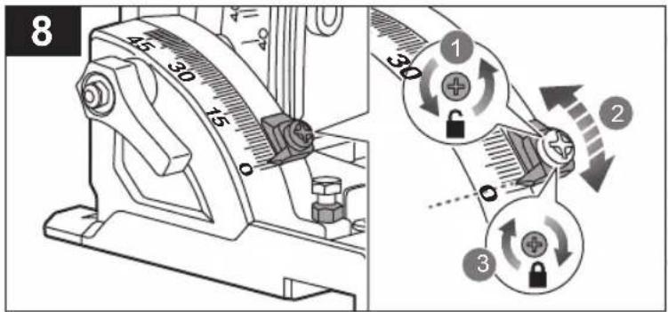
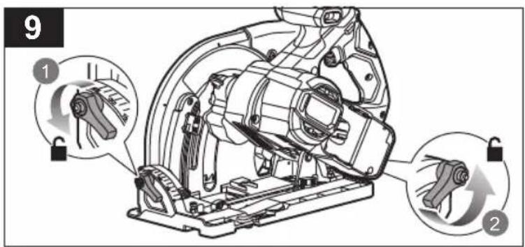
- Bevel lock knob
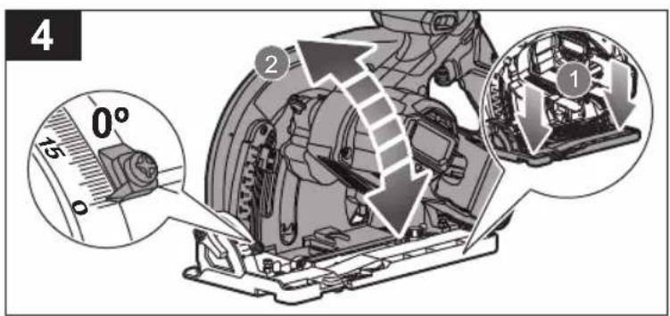
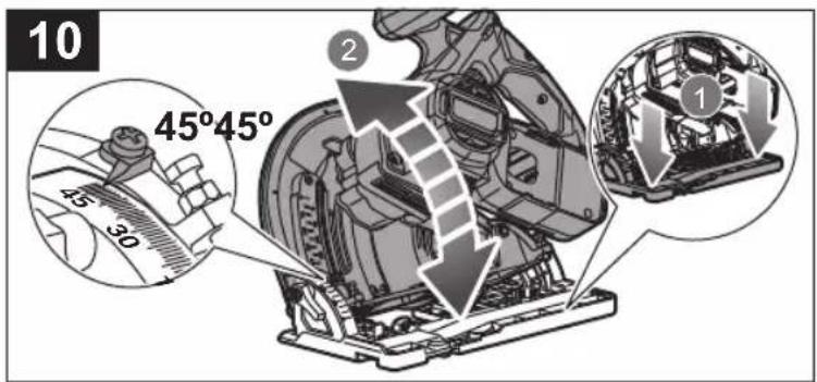
- Bevel indicator
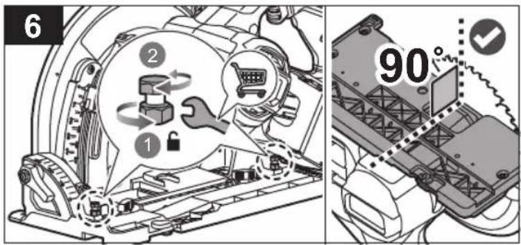
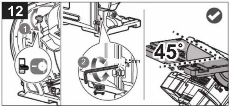
- Bevel adjustment screw
- Negative bevel angle bypass tab
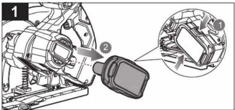
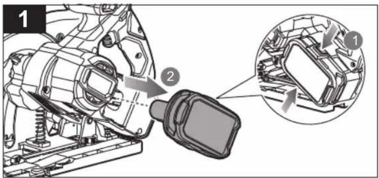
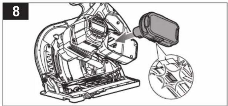
- Battery port
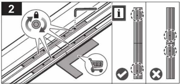
- Track clamp
- Track connector
-
Track
-
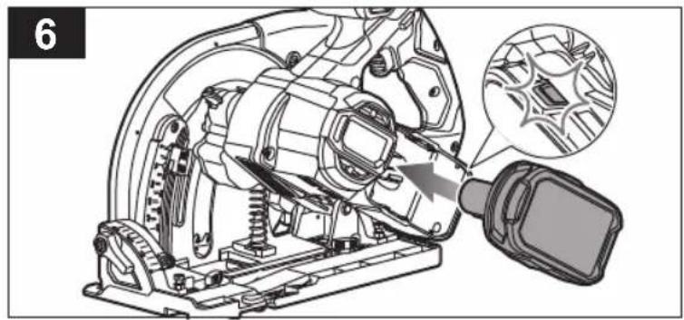
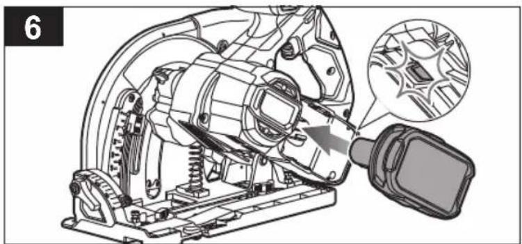
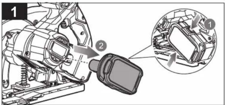
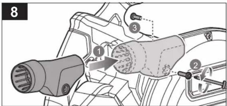
Dust port
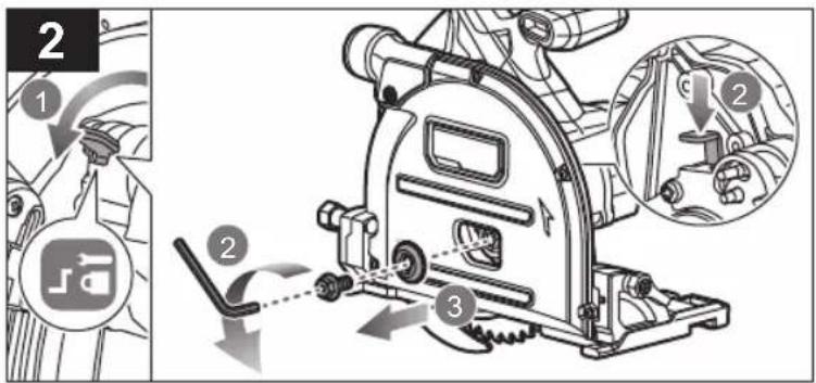
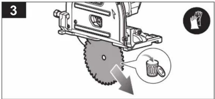
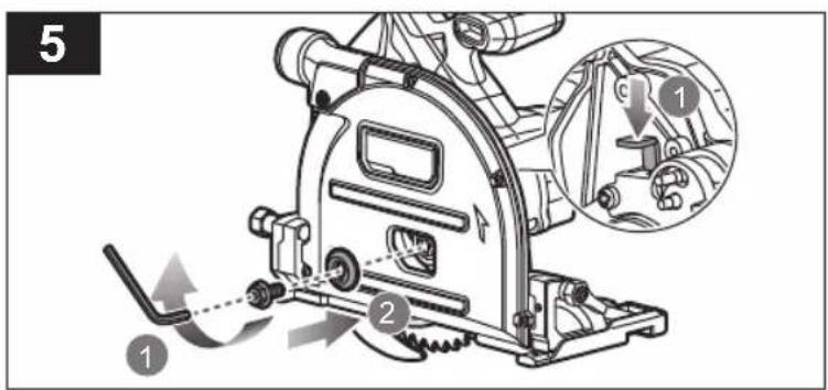
- Blade screw
- Outer flange
- Saw blade
- Riving knife
- Bevel angle bypass lever
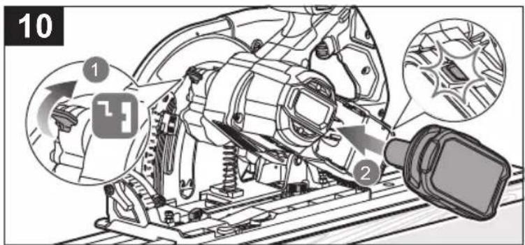
- Track adjustment lock knob
- Track adjustment tab
- Track wrench
- Blade wrench
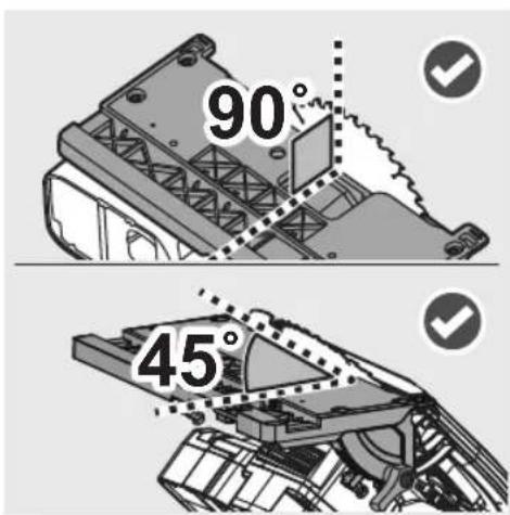
- 45° bevel setting screw
- Operator's manual
- Wrench
- Hex key
- Screwdriver
- Battery pack
- Charger
MAINTENANCE
The product should never be connected to a power supply when assembling parts, making adjustments, cleaning, performing maintenance, or when the product is not in use. Disconnecting the product from the power supply will prevent accidental starting that could cause serious injury.
- When servicing, use only original manufacturer's replacement parts, accessories and attachments. Use of any other parts may create a hazard or cause product damage.
- Avoid using solvents when cleaning plastic parts. Most plastics are susceptible to various types of commercial solvents and may be damaged by their use. Use clean cloths to remove dirt, carbon dust, etc.
- Do not at any time let brake fluids, gasoline, petroleum-based products, penetrating oils, etc., come in contact with plastic parts. Chemicals can damage, weaken or destroy plastic which may result in serious personal injury.
■ For greater safety and reliability, all repairs should be performed by an authorised service centre.
SYMBOLS ON THE PRODUCT

Safety alert
European Conformity Mark
British Conformity Mark

Ukraine Conformity Mark
EurAsian Conformity Mark

Please read the instructions carefully before starting the product.

Wear ear protection.

Wear eye protection.

Wear a dust mask.

Blade width of cut (kerf)

Number of teeth on this saw blade

For cutting wood and analogous material

Not for cutting metals

Blade rotation direction (shown on blade guard)

Do not dispose of waste batteries, waste electrical and electronic equipment as unsorted municipal waste. Waste batteries and waste electrical and electronic equipment must be collected separately. Waste batteries, waste accumulators, and light sources have to be removed from the equipment. Check with your local authority or retailer for recycling advice and collection point. According to local regulations, retailers may have an obligation to take back waste batteries and waste electrical and electronic equipment free of charge. Your contribution to the reuse and recycling of waste batteries and waste electrical and electronic equipment helps to reduce the demand of raw materials. Waste batteries, in particular containing lithium, and waste electrical and electronic equipment contain valuable and recyclable materials, which can adversely impact the environment and the human health if not disposed of in an environmentally compatible manner. Delete personal data from waste equipment, if any.
SYMBOLS IN THIS MANUAL

Lock

Unlock

Parts or accessories sold separately

Note

Warning
SYMBOLES APPLIQUÉS SUR LE PRODUIT

Alerte de sécurité

MACHEN SIE SICH MIT IHREM PRODUKT VERTRAUT
Siehe Seite 134.
SYMBOLE AUF DEM PRODUKT

Sicherheitswarnung

WERKING VAN DE AFSCHERMING
SYMBOLER PÅ PRODUKTET

Sikkerhedsadvarsel

SYMBOLER PÅ PRODUKTEN

Säkerhetsvarning
CE-märkning
SIKKERHET PÅ ARBEIDSOMRÅDET
SYMBOLER PÅ PRODUKTET

Sikkerhetsadvarsel

Europeisk samsvarsmerking

Britisk samsvarsmerking

Ukrainsk samsvarsmerking

EurAsian Konformitetstegn

ÜLDISED OHUTUSREEGLID
UPUTUSSAAGIDE OHUTUSJUHISED
SAAGIMINE
DODATNA VARNOSTNA OPOZORILA
■ Ne uporabljajte brusnih koles.
OBOZNÁMTE SA S VAŠÍM PRODUKTOM
Vid' strana 134.
natural_image
Diagram of a wooden plank with a saw cutting through it, showing a warning symbol (no text or labels present)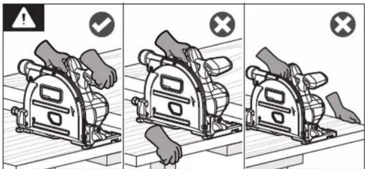
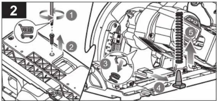
natural_image
Technical line drawing of a mechanical device with a hose and a shopping cart icon (no text or symbols)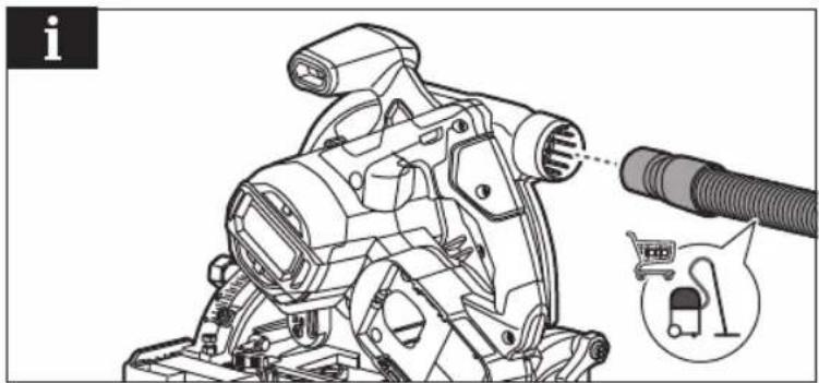
natural_image
Technical line drawing of a mechanical device with hoses and a shopping cart icon (no text or symbols)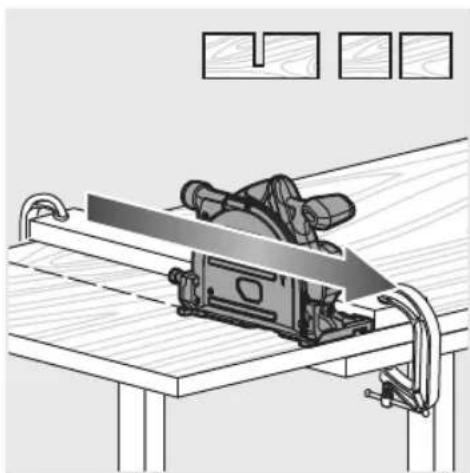
natural_image
Line drawing of a machine cutting through a wooden workbench with clamps (no text or symbols)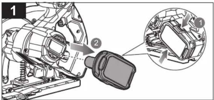
natural_image
Diagram showing a wooden table with metal clips and a magnified inset illustrating a shopping cart and lock mechanism (no text or symbols)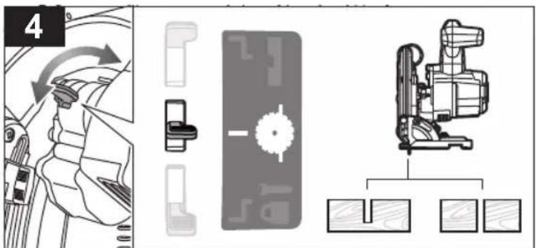
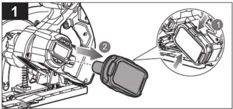
natural_image
Technical illustration of a mechanical assembly with a close-up inset showing internal components (no text or symbols)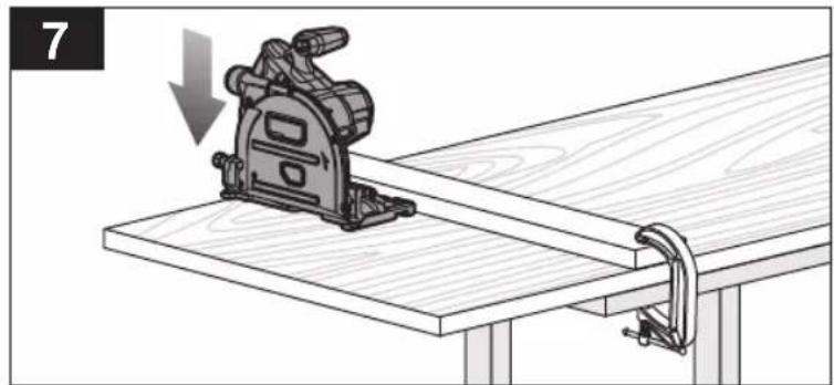
natural_image
Diagram of a wooden cutting machine on a workbench with a clamping bracket, showing a downward force (no text or symbols present)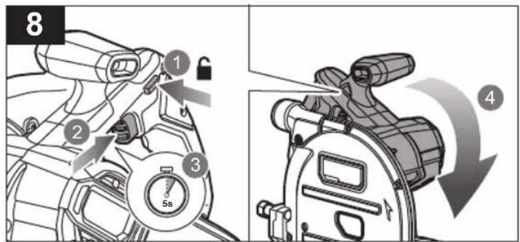
natural_image
Mechanical assembly diagram showing a cutting machine on a workbench with a clamping tool (no text or symbols)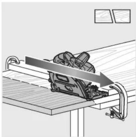
natural_image
Diagram of a mechanical setup with a tool on a workbench and clamped components, no text or symbols present.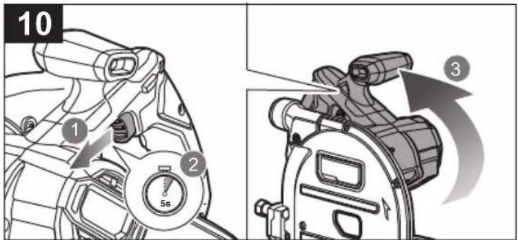
natural_image
Diagram of a cutting machine on a wooden workbench, showing a downward force and bracket (no text or symbols)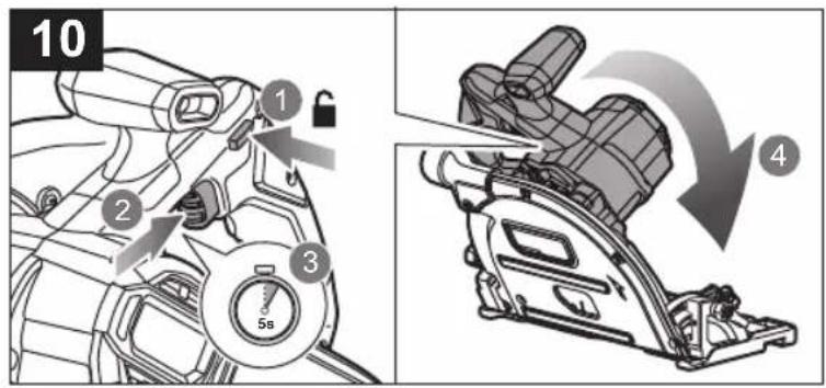
natural_image
Diagram of a machine tool cutting through a workbench, showing blade and clamping mechanism (no text or symbols)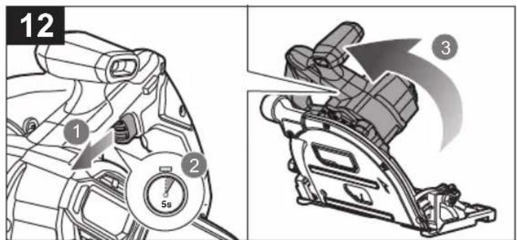
natural_image
Line drawing of a manual cutting machine on a wooden workbench (no text or symbols)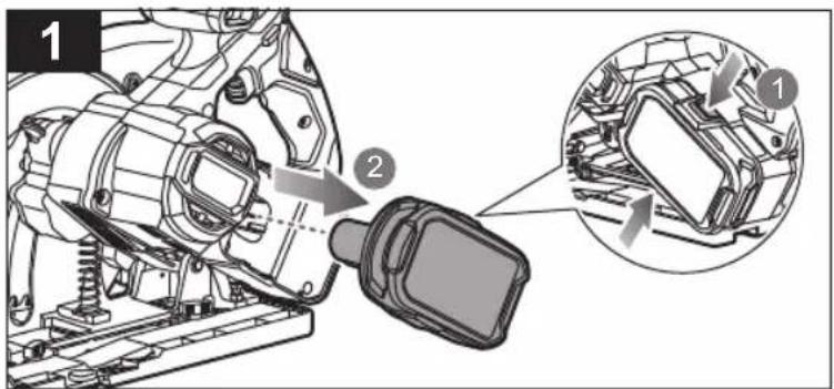
natural_image
Technical illustration of a mechanical assembly with a close-up inset showing internal components (no text or symbols)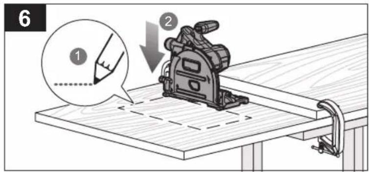
natural_image
Technical line drawing of a mechanical device with a cutting tool, mounted on a wooden base (no text or symbols visible)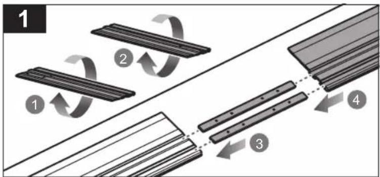
flowchart
graph TD
    A["Step 1: Rotation of rectangular components"] --> B["Step 2: Rotation of curved arrows"]
    B --> C["Step 3: Rotation of elongated rectangular elements"]
    C --> D["Step 4: Rotation of elongated rectangular parts"]

natural_image
Diagram of a mechanical component with rotational arrows indicating motion (no text or symbols)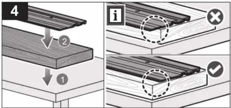
natural_image
Mechanical assembly diagram showing a component being lowered into a wooden base, with no visible text or symbols.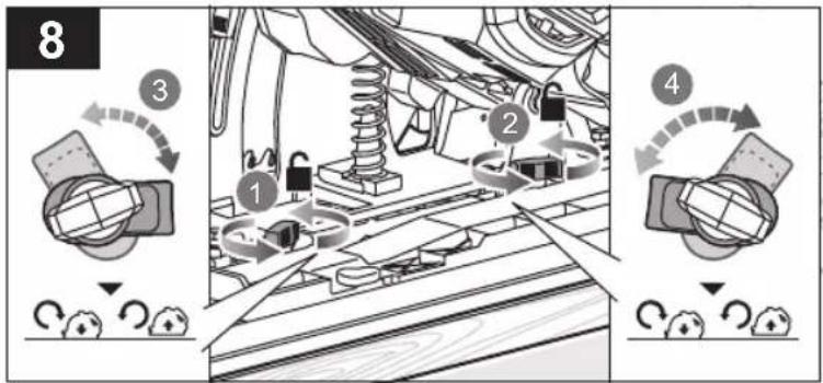
flowchart
graph TD
    A["Vehicle Assembly"] --> B{Step 1}
    B --> C["Car Suspension"]
    C --> D["Step 2"]
    D --> E["Car Maintenance"]
    E --> F["Step 3"]
    F --> G["Car Maintenance"]
    G --> H["Step 4"]
natural_image
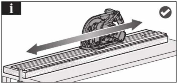
Diagram of a mechanical device on a slide with directional arrows indicating motion (no text or symbols)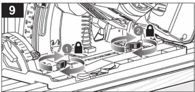
natural_image
Technical illustration of a cutting machine on a workbench, showing blade and cutting edge (no text or symbols)
natural_image
Technical illustration of a mechanical assembly on a workbench, showing a cutting tool and bracket (no text or symbols)
natural_image
Illustration of a machine tool on a workbench with a cutting tool, showing a blade and wooden base (no text or symbols)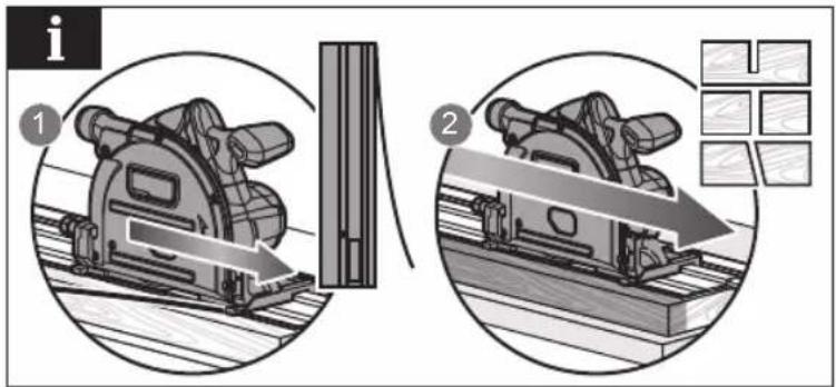


natural_image
Mechanical assembly diagram showing a component being lowered into a wooden base, with no visible text or symbols.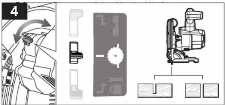
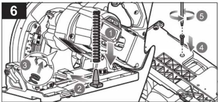
natural_image
Mechanical assembly diagram showing a motor and gear assembly with a close-up inset of a component detail (no text or symbols)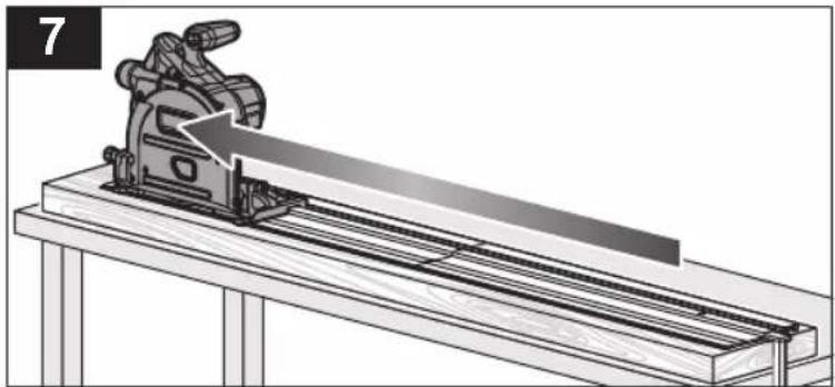
natural_image
Technical illustration of a mechanical device on a workbench, showing a cutting tool and blade assembly (no text or symbols)
natural_image
Mechanical assembly diagram showing a saw cutting tool interacting with a mechanical component (no text or symbols visible)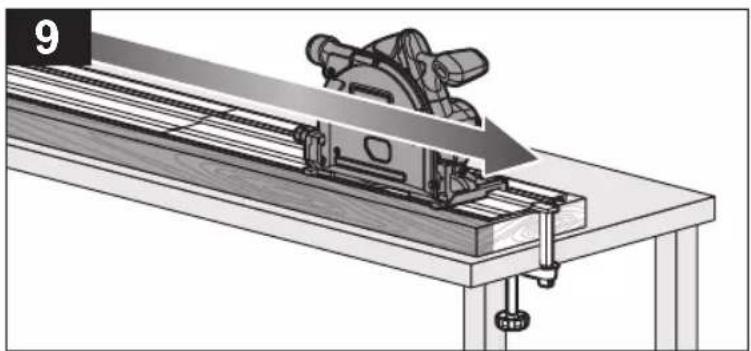
natural_image
Technical illustration of a mechanical device on a workbench, showing a blade cutting through a machine (no text or symbols present)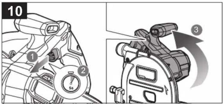
natural_image
Technical illustration of a mechanical device with a gear and motion arrow (no text or symbols)
natural_image
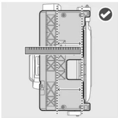
Technical diagram of a mechanical device with measurement lines and a checkmark icon (no readable text or symbols)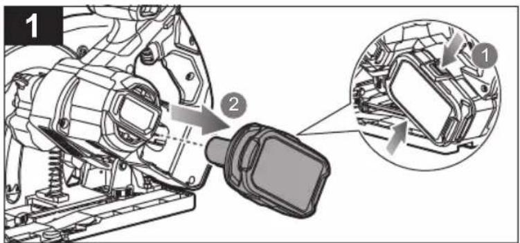
natural_image
Illustration of two cleaning tools: a mechanical component and a brush, both with sparkles indicating texture or inspection (no text or symbols present)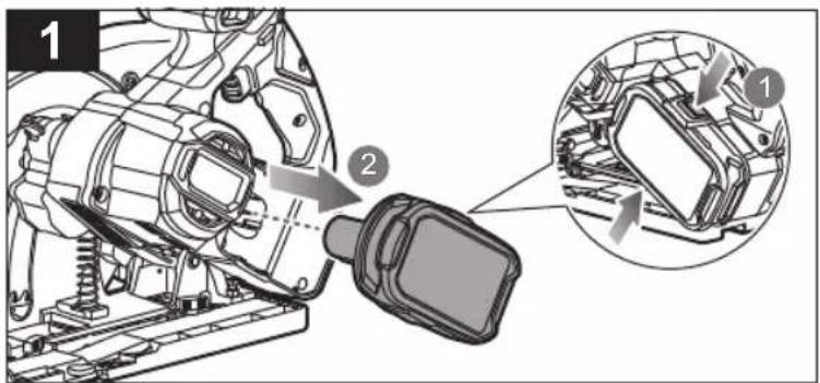

natural_image
Illustration of cleaning a car body with a brush and sparkle effect (no text or symbols)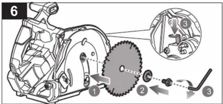
EnglishFrançaisDeutschEspañolItalianoNederlandsPortuguês
| Product specifications Caractéristiques de l'appareil | Produkt-Spezifikationen Especificaciones del producto | Specifiche prodotto Products specificaties Especificações do produto | ||||
| Plunge saw | Scie plongeante | Tauchsäge | Sierra de incisión | Troncatnice a immersione | Invalcirkelzaag | Serra de incisão |
| Model | Modèle | Modell | Modelo | Modello | Model | Modelo |
| Voltage | Tension | Spannung | Tensión | Voltaggio | Spanning | Voltagem |
| Blade diameter Diamètre du disque de coupe | Sägeblattdurchmesser | Diâmetro de la hoja | Diametro lama | Zaagblad ø | Diâmetro da lâmina | |
| Blade arbour | Arbre de lame | Sägeblattbohrungs-durchmesser | Árbol del disco | Protezione lama | Gat voor zaagblad | Armação da lâmina |
| Cutting capacity at 0° | Capacité de coupe à 0° | Schnittleistung bei 0° | Capacidad de corte a 0° | Capacità di taglio a 0° | Zaagcapaciteit bij 0° | Capacidade de corte a 0° |
| With track | Avec voie | Mit Führungsschiene | Con riel | Con guida | Met baan | Com trilho |
| Without track | Sans voie | Ohne Führungsschiene | Sin riel | Senza guida | Zonder baan | Sem trilho |
| Cutting capacity at 45° | Capacité de coupe à 45° | Schnittleistung bei 45° | Capacidad de corte a 45° | Capacità di taglio a 45° | Zaagcapaciteit bij 45° | Capacidade de corte a 45° |
| With track | Avec voie | Mit Führungsschiene | Con riel | Con guida | Met baan | Com trilho |
| Without track | Sans voie | Ohne Führungsschiene | Sin riel | Senza guida | Zonder baan | Sem trilho |
| No-load speed | Vitesse à vide | Leerlaufdrehzahl | Velocidad sin carga | Velocità a vuoto | Onbelast toerental | Velocidade em vazio |
| Blade - width of cut | Lame - Largeur de coupe | Sägeblatt - Schnittbreite | Hoja - Ancho del corte | Lama - Ampiezza di taglio | Zaagblad - Maalbreedte | Lâmina - Largura do corte |
| Blade teeth | Nombre de dents | Anzahl Sägezähne | Dientes de la hoja | Denti lame | Zaagbladtanden | Dentes da lâmina |
| Blade thickness | Epaisseur de la Lame | Dicke Stammblatt | Grosor hoja | Spessore lama | Zaagbladdikte | Espessura lâmina |
| Weight - excluding bat-tery pack | Poids, sans pack batterie | Gewicht, ohne Akkupack | Peso, sin incluir la batería | Peso, non incluso nel gruppo batteria | Gewicht, batterijpack niet inbegrepen | Peso, sem incluir a bateria |
| Weight (According to EPTA procedure 01/2014) | Poids (en respect de la procédure EPTA 01/2014) | Gewicht (Gemäß EPTA(Verfahren 01/2014) | Peso (conforme al Procedimiento EPTA 01/2014) | Peso (secondo la Procedura EPTA 01/2014) | Gewicht (volgens EPTA(procedure 01/2014) | Peso (de acordo com o Procedimento EPTA 01/2014) |
| Measured sound values determined according to EN 62841: | Valeurs du son mesuré déterminées selon EN 62841: | Gemäß EN 62841: gemessene Schallwerte | Valores medidos del sonido en función de la norma EN 62841: | Valori del suono misurati determinati secondo lo standard EN 62841: | Gemeten geluidswaarden bepaald in overeenstemming met EN 62841: | Valores medidos do som em função da norma EN 62841: |
| A-weighted sound pressure levelUncertainty K | Niveau de pression sonore pondéré-A Incertitude K | A-bewerteter Schalldruckpegel Unsicherheit K | Nivel de presión acústica ponderada en A Incertidumbre K | Livello di pressione sonora pesato A Incertezza K | A-gewogen geluidsdrukniveau Onzekerheid K | Nivel de pressão sonora ponderada A Incerteza K |
| A-weighted sound power levelUncertainty K | Niveau de puissance sonore pondéré-A Incertitude K | A-bewerteter Schallleistungspegel Unsicherheit K | Nivel de potencia acústica ponderada en A Incertidumbre K | Livello di potenza sonora pesato A Incertezza K | A-gewogen geluidsniveau Onzekerheid K | Nivel de potência sonora ponderada A Incerteza K |
| Wear ear protectors. | Portez une protection acoustique. | Tragen Sie Gehörschutz. | Utilice protección auditiva! | Indossare protezioni acustiche adeguate. | Draag corbeschermers. Sempre use a proteção dos cuvidos. | |
| The vibration total values (triaxial vector sum) determined according to EN 62841: | La valeur totale des vibrations (somme vectorielle triaxiale) a été déterminée selon EN 62841: | Die Vibrationsgesamtwerte (dreiaxiale Vektorsumme) ermittelt entsprechend EN 62841: | Los valores totales de vibrazione (Suma vectorial triaxial) se han determinado según la norma EN 62841: | I valori di vibrazione totali (somma veltlore triassiale) sono determinati secondo gli standard EN 62841: | De totale trillingswaarden (triaxiale vectorsom) werden vastgesteld in overeenstemming met EN 62841: | Os valores totais de vibração (Soma vectorial triaxial) foram determinados de acordo com a norma EN 62841: |
| Cutting woodUncertainty K | Coupe de boisIncertitude K | Sägen von HolzUnsicherheit K | Corte de maderaIncertidumbre K | Tagliare legnoIncertezza K | Hout zagenOnzekerheid K | Corte de madeiraIncerteza K |
| Replacement parts | Pièces de rechange | Ersatzteile | Piezas de repuesto | Ricambi | Vervangende onderdelen | Peças sobresselentes |
| Saw blade | Lame de scie | Sägeblatt | Cuchilla de la sierra | Lama sega | Zaagblad | Lâmina da serra |
| Riving knife | Couteau diviseur | Spaltkeil | Cuña de separación | Cuneo | Spouwmes | Faca rasgadora |
| Track | Voie | Führungsschiene | Riel | Guida | Baan | Trilho |


| DanskSvenskaSuomiNorskPycский Polski | ||||||
| Produktspecifikationer | Produktspecifikationer | Tuotteen tekniset tiedot | Produktspesifikasjoner | Xaрактеристики изделия | Parametry techniczne | |
| Dyksav | Instickssåg | Upolussaha | Dykksag | Погружная пила | Zagłębiarka | |
| Model | Modell | Malli | Modell | Модель | Model | RPLS18X |
| Spænding | Spänning | Jännite | Spenning | Напряжение | Napięcie | 18V --- |
| Klingediameter | Klingdiameter | Terän läpimitta | Bladdiameter | Диаметр режущего диска | Średnica tarczy tnącej | 165 mm |
| Klingens centerhul | Bladdom | Teräkara | Bladaksel | Вал для пильного полотна | Otwór osiowy tarczy | 15,88 mm |
| Skarekapacitet ved 0° | Kapkapacitet vid 0° | Leikkuusvyys asennossa 0° | Skjaredybde ved 0° | Толщина реза при 0° | Zakres cięcia przy 0° | |
| Med spor | Med spår | Kiskolla | Med spor | Ширина шины | Z prowadnicą | 49 mm |
| Uden spor | Utan spår | Ilman kiskoa | Uten spor | Без шины | Bez prowadnicy | 54 mm |
| Skarekapacitet ved 45° | Kapkapacitet vid 45° | Leikkuusvyys asen-nossa 45° | Skjaredybde ved 45° | Толщина реза при 45° Zakres cięcia przy 45° | ||
| Med spor | Med spår | Kiskolla | Med spor | Ширина шины | Z prowadnicą | 36,5 mm |
| Uden spor | Utan spår | Ilman kiskoa | Uten spor | Без шины | Bez prowadnicy | 40 mm |
| Tomgangshastighed | Tomgangshastighet | Tyhjäkäyntinopeus | Hastighet ubelastet | Скорость на холостом ходу | Prędkość bez obciążenia | 4300 min-1 |
| Klinge - Snitbredde | Sågkinga - Skärbredd | Terä - Leikkauksen leveys | Blad - Bredde på kappet | Лезвие - Ширина разреза | Tarcza - Szerokość cięcia | 1,6 mm |
| Klingetænder | Sågtand | Terän hampaat | Bladtenner | Число зубьев | Liczba zębów tarczy | 24 T |
| Klingetykkelse | Sågkingatjocklek | Teräpaksuus | Blad tykkelse | Толщина Лезви | Grubość Tarcza | 1,0 mm |
| Vægt, ekskl. batteripakke | Vikt, exklusive batteri | Paino ilman akkua | Vekt (uten batteripakke) | Вес без батареи | Masa - bez akumulatora | 3,2 kg |
| Vægt (i henhold til EPTA(procedure 01/2014) | Vikt (enligt EPTA(förfarandel 01/2014) | Paino (EPTA(merettielyn 01/2014 mukaisesti) | Vekt (prosedyre 01/2014) Bec | (в соответствии с Процедурой 01/2014 Европейской ассоциации производителей электронструмента) | Masa (zgodnie z procedurą EPTA 01/2014) | 3,7 kg (1,5 Ah) - 4,4 kg (9,0 Ah) |
| Mälte lydværdier bestemt iht. EN 62841: | Uppmätta ljudvärden enligt EN 62841: | Milatut arvot määrletty EN 62841: standardin mukaan: | Mälte lydverdier bestemt iht. EN 62841: | Измеренные значения параметров звуха определены в соответствии с EN 62841: | Zmierzone wartości akustyczne zgodnie z normą EN 62841: | |
| A-vægtet lydtryksniveau | A-vägd ljudtrycksnivå | A-paintettu äänenpainetaso | A-vektet lydtrykknivå | Уровень А-взвешенного звукового давления | A-ważony poziom ciśnienia hałasu | I_px = 94,51 dB(A) |
| Usikkerhed K | Osäkerhet K | Epätarkkuus K | Usikkerhet K | Погрешность K | Niepewność pomiaru K | 3 dB(A) |
| A-vægtet lydeffektniveau | A-vägd ljudeffektsnivå | A-paintettu äänenteho | A-vektet lydeffektnivå | Уровень А-взвешенной звуковой мощности | A-ważony poziom mocy akustycznej | I_px = 105,51 dB(A) |
| Usikkerhed K | Osäkerhet K | Epätarkkuus K | Usikkerhet K | Погрешность K | Niepewność pomiaru K | 3 dB(A) |
| Bær høreværn. | Bär hørselskydd. | Käytä korvasucija. | Bruk hørselsvern. | Используйте наушники! | Stosować środki ochrony sluchu! | |
| De totale vibrationsvaerdier (triaxial vektorsum) er bestemt i henhold til EN 62841: | De totala vibrationsvärderna (triaxial vektorsumma) bestäms enligt EN 62841: | Tärinän kokonaisarvot (kolmiakselinen vektorisumma) määritetlynä standardien EN 62841 mukaisesti. | De totale vibrasjonsverdiene (treakset vektorsum) er i henhold til EN 62841: | Суммарное значение вибрации (сумма векторов по трем координатным осям) определено в соответствии со стандартом EN 62841: | Wartości sumaryczne drgań (suma wektora trójosiowego) określone zgodnie z normą EN 62841: | |
| Skæring i træ | Sága trå | Puun leikkaaminen | Kapping av tre | Резание древесины | Cięcie drewna | a_t = 1,64 m/s^2 |
| Usikkerhed K | Osäkerhet K | Epätarkkuus K | Usikkerhet K | Погрешность K | Niepewność pomiaru K | 1,5 m/s |
| Reservedele | Reservdelar | Varaosat | Reservedeler | Запасные части | Części zamienne | |
| Savklinge | Sågblad | Sahanterä | Sagblad | Пильное полотно | Tarcza tnąca | RAPSB165 (5132005997) |
| Spaltekniv | Rivningskniv | Suojakilla | Spaltekniv | Расклинивающий ножк | Klin rozszczepiający | 089240074113 |
| Spor | Spår | Kisko | Spor | Шина | Prowadnica | 089240074701 |


| Čeština | Magyar | Română | Latviski | Lietuviškai | Eesti |
| Technické údaje produktu | Termék műszaki adatai | Specificațiile produsului | Produkta specifikácijas | Gaminio techninės savybės | Toote tehnilised andmed |
| Ponomá okružni pila | Merülőfűrész | Fierăstrău cu șină | Iegremdėjamais ripzágis | Diskinis pjūklas | Uputussaag |
| Model | Tipus | Model | Modelis | Modelis | Mudeli tāhis |
| Elektrické napětí | Feszültség | Tensiune | Spriegums | Itampa | Pinge |
| Průměr kotouče | Tárcsa átmérője | Diametru lamă | Asmens diametrns | Pjovimo disko skersmuo | Saeketta lábimõõt |
| Hřídel kotouče | Fürésztárcsa tengelye | Arbore disc | Asmens centra izmērs | Disko ašis | Ketta võil |
| Řezací kapacila při 0° | Kapacitet rezanja 0°-nál | Capacitate de tăiere la 0° | Zăgėšanas jauda pie 0° | Pjovimo našumas pjaunant 0° kampu | Lõikesügavus nurgal 0° |
| S posuvem | Sinnel | Cu șină | Ar zăgėšanas sliedi | Su bégeliais | Trajektooriga |
| Bez posuvu | Sín nélkül | Fără șină | Bez zăgėšanas sliedes | Be bégelių | Trajektoorita |
| Řezací kapacila při 45° | Vágási kapacitás 45°-nál | Capacitate de tăiere la 45í | Zăgėšanas jauda pie 45° | Pjovimo našumas pjaunant 45° kampu | Lõikesügavus nurgal 45° |
| S posuvem | Sinnel | Cu șină | Ar zăgėšanas sliedi | Su bégeliais | Trajektooriga |
| Bez posuvu | Sín nélkül | Fără șină | Bez zăgėšanas sliedes | Be bégelių | Trajektoorita |
| Otláčky naprázdno | Úresjáratí fordulatszám | Víteză în gol | Tukšgailas átrums | Greilis be apkrovimo | Kiirus ilma koormusela |
| Pilový kotouč - Šířka fezu | Fürészlemez - Marási szélesség | Lamă - Látjme a tăieri | Ripa - Griezuma platums | Geležtė - Pjovimo plotis | Saeketas - Lõikelaius |
| Zub kotouče | Fürészlap fogai | Dinte lamă | Asmens zobi | Geležtės dantukų skaičius | Lõiketera hammas |
| Pilový kotouč Tlouštka | Vastagság Fürészlemez | Grosime Lamă | Ripa biezums | Geložtė storis | Saeketas paksus |
| Hmotnost, bez akumulá-torového modulu | Súly, akkumulátor nélkül | Greutale, neinclus acumulatorul | Svars, bez baterijas pakas | Svoris be baterijų paketo | Kaal ilma akupaketila |
| Hmotnost v souladu s postu-pem EPTA 01/2014 | Súly (a 2014/01 EPTA eljárás szerint) | Greutale (conform procedurii EPTA 01/2014) | Svars (saskaņa ar EPTA procedūru 01/2014) | Svoris (pagal EPTA procedūrą 01/2014) | Kaal (vastavalt EPTA(protseduurile 01/2014) |
| Naměřené hodnoty hluku zjištěné dle EN 62841: | A hang értékek meghatározása az EN 62841: szerint történt: | Valori de sunet măsurate determinate în conformitate cu EN 62841: | Izměrítás skaņas vērtības ir noteiktas saskaņa ar EN 62841: | Išmatuotos garso vertės nustatytos pagal EN 62841: | Mõõteväärtused on kindlaks määratud vastavalt standardile EN 62841: |
| Hladina akustického tlaku vážená funkci A Nejistota K | A-súlyozott hangny-omásszint Bizonytalanság K | Nivel de presiune acustică ponderată A Incertitudine K | A-līmeņa skaņas spiediena līmenis Nenoteiktība K | A svertinis garso slėgio lygis A-kaalutud helirōhu tase K nepastovumas | Māāramatus K |
| Hladina akustického vykonu vážená funkci A Nejistota K | A-súlyozott hangteljesit-ményszint Bizonytalanság K | Nivel de putere acustică ponderată A Incertitudine K | A-līmeņa skaņas jaudas līmenis Nenoteiktība K | A svertinis garso galios lygis K nepastovumas | A-kaalutud helivõimsuse tase Māāramatus K |
| Používejte chráníče sluchu. | Viseljen hallásvédót. | Purtají aparatoare de urechi. | Lietojiet dzirdes aizsargus. | Naudokite ausų apsaugos priemones. | Kasulage kuulmiskaitsevahendeid. |
| Celkovė hodnoty vibraci (Trojosy vektorový součet) určenė v souladu s EN 62841: | A vibráció teljes értékei (háromtengelyū vektorösszeg), az EN 62841 szerint meghatározva. | Valorile totale ale vibrațiilor (sumă vector triaxială) au fost determinate în conformitate cu EN 62841: | Vibrácijas kopējās vērtības (triaksială vektoru summa) ir noteiktas atbilstoši EN 62841: | Bendros vibracijos vertės (triàsio vektoriaus suma) nustatomos pagal EN 62841: | Vibratsiooni üldväärtus (kolme suuna vektorsumma) on kindlaks määratud vastavalt standarditele EN 62841: |
| Řezání dřeva | Fa vágása | Lemn de tăiere | Koksnes griešana | Medienos pjovimas | Puidu saagimine |
| Nejistota K | Bizonytalanság K | Incertitudine K | Nenoteiktība K | K nepastovumas | Māāramatus K |
| Náhradní díly | Cserealkatrészek | Piese de schimb | Mainas delajas | Alsarginės dalys | Varuosad |
| Pilový kotouč | Fürészlap | Lama ferăstrăului | Zăga asmens | Pjūklo geležtė | Saeleht |
| Rozviraci klin | Hasitókės | Cujit de despicare | Plešanas ģlīls | Skélimo peilis | Lõikekil |
| Kolejnice posuvu | Sin | Şină | Zăgėšanas sliede | Bégeliai | Trajektoor |
The declared noise emission value(s) have been measured in accordance with a standard test method, and may be used for comparing one tool with another.
The declared noise value(s) may also be used in a preliminary assessment of exposure.
The noise emissions during actual use of the power tool can differ from the declared values depending on the ways in which the tool is used especially what kind of workpiece is processed.
Identify safety measures to protect the operator based on an estimation of exposure in the actual conditions of use (taking account of all parts of the operating cycle such as the times when the tool is switched off and when it is running idle in addition to the trigger time).
Wear hearing protection. Exposure to noise can cause hearing loss.
FR

AVERTISSEMENT
EN RYOBI WARRANTY APPLICATION CONDITIONS
In addition to any statutory rights resulting from the purchase, this product is covered by a warranty as stated below.
- The warranty period is 24 months for consumers and commences on the date the product was purchased. This date has to be documented by an invoice or other proof of purchase. The product is designed and dedicated to consumer and private use only. So there is no warranty provided in case of professional or commercial use. This warranty applies only on new products.
- There is a possibility to extend for a part of the range of power tools (AC/DC) the warranty period over the period described above using the registration on the www.ryobitools.eu website. The eligibility of products for extended warranty is clearly displayed in stores and / or on packaging and is contained within the product documentation. The end user is required to register his/her newly-acquired products online within 30 days from the date of purchase. The end user may register for the extended warranty in his/her country of residence if listed on the online registration form where this option is valid. Furthermore, end users must give their consent to the storage of their personal data that is required to be entered online. They must also accept the terms and conditions. The registration confirmation receipt, which is sent out by e-mail, and the original invoice showing the date of purchase will serve as proof of the extended warranty.
- The warranty covers all defects of the product during the warranty period due to faults in workmanship or material at the purchase date. The warranty is limited to repair and/or replacement and does not include any other obligations including but not limited to incidental or consequential damages. The warranty is not valid if the product has been misused, used contrary to the instruction manual, or has been incorrectly connected to a power supply. This warranty does not apply to:
– any damage to the product that is the result of improper or lack of maintenance – any product that has been altered or modified
– any product where original identification (trade mark, serial number) markings have been defaced, altered or removed
– any damage caused by non-observance of the instruction manual
– any product not displaying the CE approval mark on the rating plate
– any product that has been attempted to be repaired by a non-authorised warranty service centre or without prior authorisation by Techtronic Industries
– any product connected to improper power supply (amps, voltage, frequency)
– any damage caused by external influences (water, chemical, physical, shocks) or foreign substances
– normal wear and tear spare parts
– inappropriate use, overloading of the tool
– use of non-approved accessories or parts
- Power tool accessories provided with the tool or purchased separately, including but not limited to screw driver bits, drill bits, abrasive discs, sand paper and blades, lateral guide, etc.
-
Components (parts and accessories) subject to natural wear and tear, including but not limited to service & maintenance kits, carbon brushes, bearings, chuck, SDS drill bit attachment or reception, power cord, auxiliary handle, transport carry case, sanding plate, dust bag, dust exhaust tube, felt washers, impact wrench pins & springs, etc.
-
For servicing, the product must be sent or presented to a RYOBI authorised service station listed for each country in the following list of service station addresses. In some countries your local RYOBI dealer undertakes to send the product to the RYOBI service organisation. When sending a product to a RYOBI service station, the product should be safely packed without any dangerous contents such as petrol, marked with sender's address and accompanied by a short description of the fault.
- A repair / replacement under this warranty is free of charge. It does not constitute an extension or a new start of the warranty period. Exchanged parts or products become our property. In some countries delivery charges or postage will have to be paid by the sender. Your statutory rights arising from the purchase of the product remain unaffected
- This warranty is valid in the European Community, Switzerland, Iceland, Norway, Liechtenstein, Turkey, Russia, and the United Kingdom. Outside these areas, please contact your authorised RYOBI dealer to determine if another warranty applies.
AUTHORISED SERVICE CENTRE
Any request or issue with the product can be addressed to your local authorised service centres (visit www.ryobitools.eu) or directly to: Techtronic Industries GmbH, Max Eyth Straße 10, 71364 Winnenden, Germany. Please state the serial number and product type printed on the label.
FR RYOBI CONDITIONS D'APPLICATION DE LA GARANTIE
EN EC DECLARATION OF CONFORMITY
Plunge saw
Brand: RYOBI | Manufacturer ^1 | Model number ^2 | Serial number range ^3
We declare as the manufacturer under our sole responsibility that the product mentioned below fulfills all the relevant provisions of the following European Directives, European Regulations and harmonised standards ^4 Authorised to compile the technical file: ^5
FR DÉCLARATION CE DE CONFORMITÉ
Scie plongeante
Max-Eyth-Straße 10, 71364 Winnenden, Germany
^2 RPLS18X
^3 48633701000001 - 48633701999999
^4 2006/42/EC, 2014/30/EU, 2011/65/EU, EN IEC 55014-1:2021, EN IEC 55014-2:2021, EN 62841-1:2015, EN 62841-2-5:2014, EN IEC 63000:2018

Alexander Krug
Managing Director
Max-Eyth-Straße 10, 71364 Winnenden, Germany
GB-DECLARATION OF CONFORMITY
Manufacturer: Techtronic Industries GmbH
Max-Eyth-Straße 10, 71364 Winnenden, Germany
We declare as the manufacturer under our sole responsibility that the product mentioned below
Plunge saw
Brand: RYOBI
Model number: RPLS18X
Serial number range: 48633701000001 - 48633701999999
fulfills all the relevant provisions of the following Regulations: S.I. 2008/1597 (as amended), S.I. 2016/1091 (as amended), S.I. 2012/3032 (as amended) and that the following designated standards have been used:
BS EN IEC 55014-1:2021, BS EN IEC 55014-2:2021,
BS EN 62841-1:2015, BS EN 62841-2-5:2014, BS EN IEC 63000:2018

Alexander Krug
Managing Director
Authorised to compile the technical file:
Techtronic Industries (UK) Ltd
Parkway
Marlow Bucks SL7 1YL
UK

EN RYOBI is a trade mark of Ryobi Limited, and is used under license.
natural_image
Three vertical panels with diagonal striped patterns, no text or symbols presentTechtronic Industries GmbH
Max-Eyth-Straße 10,
71364 Winnenden, Germany
Techtronic Industries (UK) Ltd
Parkway
Marlow Bucks SL7 1YL
UK
20230412v1b